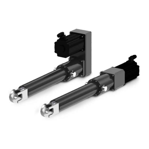
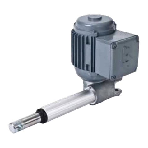
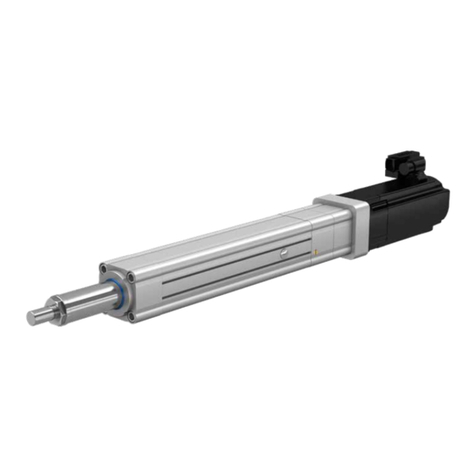
Ewellix CAHB-2 Series User manual

CATEGORY
MAX 2 LINES
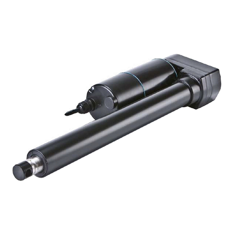
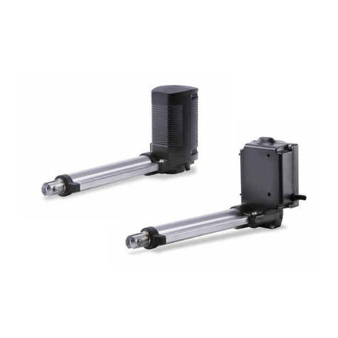
CAHB-2x series
Linear actuator CAHB-20E and 20S
CAHB-21E and 21S
CAHB-22E and 22S
INSTALLATION, OPERATION AND MAINTENANCE MANUAL

2
CAHB-20 series
Contents
Indice
1.0 General information ...................................................4
1.1 Information on this manual ..........................................4
1.2 Explanation of symbols and signal words ...................4
1.3 Limitation of liability .....................................................5
1.4 Warranty terms.............................................................5
1.5 Customer service .........................................................5
2.0 Safety ...........................................................................6
2.1 Limitation of liability .....................................................6
2.1.1 Intende d use ............................................................6
2.2 Responsibility of the owner and processor .................6
2.2.1 Qualications ...........................................................7
2.2.2 Specicdangers......................................................7
2.3 Safety equipment .........................................................7
2.4 Changesandmodicationsontheactuator ...............8
3.0 Technical data.............................................................9
3.1 Operating conditions....................................................9
3.2 Operating voltages and limits .................................... 10
3.3 Product label .............................................................. 11
4.0 Structure and function.............................................12
4.1 O ve r vi ew ..................................................................... 12
4.2 Brief description ......................................................... 15
4.3 Special features.......................................................... 15
4.4 Construction group description ................................ 17
4.5 Connection ................................................................. 17
4.6 Options ....................................................................... 18
4.6.1 Limit switch ............................................................ 18
4.6.2 Potentiometer (E design only) ............................... 18
4.6.3 Absolute analog position output ........................... 18
4.6.4 Encoder.................................................................. 19
4.6.5 Termination resistor integrated.............................. 19
4.6.6 Manual Override..................................................... 19
4.6.7 Smart CAHB-2xS function.....................................20
5.0 Transport, packaging and storage.........................21
5.1 Safety information for the transport........................... 21
5.1.1 Transport inspection.............................................. 21
5.1.2 Return to the manufacturer....................................21
5.1.3 Packaging ..............................................................21
5.2 Storage .......................................................................21
6.0 Installationandrstoperation ...............................22
6.1 Installation location ....................................................22
6.2 Installation ..................................................................22
6.3 Inspectionspriortorstoperation.............................23
6.4 Connect to power supply........................................... 24
6.4.1 E design wiring scheme......................................... 24
6.4.2 DenemovingdirectionVSpower“+”,“-”
(E design only) .................................................................. 24
6.4.3 S design wiring scheme.........................................25
7.0 CAN bus SAE J1939 protocol (S design only) ......26
7.1 Transmission rate .......................................................26
7. 2 C A N - I D .......................................................................26
7.2.1 CAN-ID distribution................................................26
7.2.2 CAN-ID in synchronous mode............................... 26
7.3 Feedback message ....................................................27
7.3.1 Error code .............................................................. 27
7.4 Control message ........................................................28
7.4.1 Switching between I/O command and
CAN bus control ............................................................... 28
7.5 Example for CAN bus protocol ..................................29
7.5.1 Feedback ...............................................................29
7.5.2 Control ...................................................................29
8.0 Operation...................................................................30
8.1 Safety..........................................................................30
8.2 Action before operation .............................................30
8.3 Action during operation..............................................30
8.3.1 Normal operation ...................................................30
8.4 Disengagement in case of emergency ...................... 31
8.5 Action after use .......................................................... 31

33
WARNING
Readthismanualbeforeinstalling,operatingormaintainingthis
actuator. Failure to follow safety precautions and instructions could
causeactuatorfailureandresultinseriousinjury,deathorproperty
damage.
9.0 Maintenance..............................................................32
9.1 Spare parts.................................................................32
9.2 Maintenance plan.......................................................32
9.3 Maintenance work ......................................................33
9.3.1 Cleaning .................................................................33
9.3.2 Inspections and readings ......................................33
9.3.3 Check of visual condition ......................................33
9.4 Measures after completed maintenance ...................33
10.0 Malfunctions .............................................................34
10.1 Troubleshooting..........................................................35
10.2 Startofoperationafterxingmalfunction.................35
11.0 Dismantling ...............................................................36
11.1 Dismantli ng.................................................................36
11.1.1 Dismantling of CAHB-20x series ...........................36
11.2 Disposal......................................................................36
12.0 Appendix....................................................................37

4
CAHB-20 series
1.0 General information
1.1 Information on this
manual
This manual provides important information on how to work
withtheactuatorsafelyandeciently.
Themanualispartoftheactuator,mustalwaysbekeptin
the actuator’s direct proximity and should be available for
the personnel at any time. All personnel working with the ac-
tuator must read and understand this manual before starting
anywork.Strictcompliancewithallspeciedsafetynotes
and instructions is a basic requirement for safety at work.
Moreover,theaccidentpreventionguidelinesandgeneral
safety precautions applicable at the place of use of the actu-
ator must also be complied with.
Forbetterrepresentationofcircumstances,theillustrations
used are not necessarily to scale and may vary from the ac-
tual design of the actuator.
1.2 Explanation of
symbols and signal words
Safety precautions
Safetyprecautionsareidentiedbysymbolsandsignal
words. These signal words indicate the severity of the
hazard.
Adhere to these safety precautions and act cautiously in or-
dertoavoidaccidents,personalinjuriesanddamageto
property.
DANGER
Indicatesadangeroussituation,which
will lead to death or serious personal
injury,iftheprecautionarymeasuresare
ignored.
WARNING
Indicatesadangeroussituation,which
can lead to minor or moderate injury or
propertydamage,iftheprecautionary
measures are ignored.
CAUTION
Indicatesadangeroussituation,which
can lead to minor or moderate injury
the precautionary measures are ignored.
NOTE
Emphasizes useful hints and
recommendations as well as information
forecientandtrouble-freeoperation.

5
1.0 General information
1.3 Limitation of liability
All information and notes in this manual were compiled un-
derdueconsiderationofvalidstandardsandregulations,the
present status of technology and our years of knowledge
and experience.
The manufacturer will not be liable for damage resulting
from:
• disregarding this manual
• unintended use
• employment of untrained personnel
• unauthorized conversions
• technicalmodications
• manipulation or removal of the screws on the actuator
• use of unapproved spare parts
Incasetheactuatoriscustomised,theactualproductdeliv-
eredmaybedierentfromwhatisdescribedinthemanual.
Inthiscase,askEwellixforanyadditionalinstructionsor
safety precautions relevant to these actuators.
Wereservetherighttomaketechnicalmodicationstothe
actuator to improve usability.
1.4 Warranty terms
Theapplicableandeectivewarrantytermsarethosecon-
tained in the manufacturer’s terms and conditions of sale.
1.5 Customer service
Ewellix Customer Service is always available to provide tech-
nical information and answer questions.
The contact information for Ewellix Customer Service can be
found on www.ewellix.com.

6
CAHB-20 series
6
2.0 Safety
2.1 Limitation of liability
This chapter provides an overview of important safety pre-
cautions and information necessary for safe and trou-
ble-freeinstallation,operationandmaintenance.
DisregardingthisManualandsafetyprecautionsspecied
therein may result in considerable danger and possible seri-
ous injury or death.
2.1.1 Intended use
The actuator has been designed and built exclusively for its
intended purpose as described in these instructions.
WARNING
Risk from misuse!
Any utilization of this actuator beyond its intended purpose may
lead to potentially hazardous situations.
Therefore:
• Strictly adhere to all safety precautions and instructions in this
manual.
• Donotallowthisactuatortobesubjectedtoweatherconditions,
strongUVrays,corrosiveorexplosiveairmediaaswellasother
aggressive media.
• Donotmodify,retoolorchangethestructuraldesignorindividual
components of the actuator.
• Never use the actuator outside of the technical application and
operational limits.
Anyinjury,damageorlosscausedbyviolationofthesein-
structions will be the responsibility of the customer.
2.2 Responsibility of the
owner and processor
The actuator is designed for personal use and is also used
in commercial applications by owner or processors.
The processor is the contracting partner of the reseller or
the manufacturer. The processor installs the actuator in a
complete system (application).
The owner of the system is therefore subject to require-
ments of the Occupational Health and Safety Act.
InadditiontothesafetyinstructionsinthisManual,the
owner or processor must do the following concerning these
safety and acci-dent prevention guidelines and environmen-
tal precautions regulations applicable to the site of the sys-
tem’s installation:
• Inform themselves of applicable industrial safety precau-
tions and determine additional hazards that arise due to
thespecicworkingconditionsprevailingatthesitewhere
the actuator is installed using risk assessment. The risk
assessment must be implemented in the form of work in-
structions for the actuator operation.
• Conrmthattheworkinstructionscreatedforthesystem
including the actuator satisfy current legal requirements
and must alter the instructions if they don’t.
• Clearly regulate and specify the responsibilities for instal-
lation,operation,maintenance,andcleaning.
• Ensure that all employees who deal with the actuator have
read and understood this Manual.
• Provide personnel with the required protective equipment.
Inaddition,ownermusttrainpersonnelatregularintervals
and inform personnel of the hazards.
Inaddition,ownerorprocessorsmustensurethattheactua-
tor is in an adequate working condition. They must do the
following:
• Ensure that the maintenance intervals described in these
instructions are complied with.
• Have all safety devices inspected regularly for function and
completeness.
WARNING
Risk from misuse!
AnImproperinstallation,operationandmaintenancecanresultin
seriousinjury,deathorpropertydamage.
Useonlyqualified,instructed,ortrainedpersonnel(asdescribed
below)whohaveread,understandandfollowtheseinstructions.

7
2.0 Safety
7
2.2.1 Qualications
Thefollowingqualicationsarespeciedfordierentareas
of activity listed in the Manual.
• An instructed person (Operator)
has been instructed by the customer in an orientation ses-
sion on the assigned tasks and possible dangers in case of
improper behaviour.
• Qualiedpersonnel
basedontheirprofessionaltraining,know-howandexperi-
ence as well as knowledge of the applicable standards and
regulations is able to perform assigned work activities and
to detect and avoid possible dangers on their own.
• A professional electrician
basedonhis/herprofessionaltraining,know-howandex-
perience as well as knowledge of the applicable standards
and regulations is able to perform work on electrical sys-
tems and to detect and avoid possible dangers on his/her
own. The professional electrician has been trained for the
special location where he/she works and knows the rele-
vant standards and regulations.
Only persons who are expected to perform their tasks reli-
ably are permitted as personnel. Persons whose reaction
capabilityisimpaired,e.g.throughdrugs,alcoholormedi-
cation,arenotpermitted.
2.2.2 Specic dangers
The following section lists the residual risks that have been
determined by the risk assessment.
• Heedthesafetyinstructionslistedhere,andthewarnings
insubsequentchaptersofthisManual,toreducehealth
hazards and to avoid dangerous situations.
DANGER
Danger to life caused by electric current!
Touching conductive parts causes a direct danger to life. Damage
to insulation or individual components can cause danger to life.
Therefore:
• Intheeventofdamagetoinsulation,switchothepowersupply
immediately and have the parts repaired.
• Work on the electrical system must be carried out only by profes-
sional electricians.
• De-energize the machine for all work on the electrical system.
• Beforemaintenance,cleaningorrepairwork,switchothepower
supply and perform lockout procedures so it cannot be turned on
again.
• Donotbridgefusesormakethemineective.Whenchanging
fuses,makesureyouusethecorrectamperage.
• Keepmoistureawayfromconductiveparts.Ifyoudon’t,thiscan
cause short circuit.
WARNING
Danger of injury caused by moving components!
Rotating and/or linearly moving components can cause severe injury.
Therefore:
• Donotworkonorplaceanyofyourbody,hands,orarmsnear
moving components.
2.3 Safety equipment
WARNING
Danger due to malfunctioning safety equipment!
Forsafeoperation,besureallsafetyequipmentisingoodworking
order.
Therefore:
• Always check functionality of safety equipment according to the
maintenance plan.
• Never disengage safety equipment.
• Safetyequipmentmayneverbeby-passedormodied.
Integration in an emergency-stop system
required (for certain applications)
The actuator is only intended for installation into an an appli-
cation or system. It does not have its own operating control
elements and does not have an independent
emergency-stop-function.
Installtheactuatorsothatitispartofanemergencyshut-o
system and can be stopped if necessary.
Theemergencyshut-osystemhastobeconnectedinsuch
a way that a disruption of the power supply or the reactiva-
tion of the power supply after a power disruption cannot
cause a hazardous situation for persons and objects.
Theemergencyshut-osystemsmustalwaysbefreelyac-
cessible.
NOTE
The processor decides which applications require the
installation of an emergency shut-off system.

8
CAHB-20 series
The following safety features may have been
installed:
A thermal switch is integrated into the motor inside to pre-
vent damage from overheating. If overheating occurs when
theactuatorisoperating(overspecication),theswitch
wouldbeactivated,thepowerwouldbecut-o;afterthe
temperaturefallsbelowthethreshold,theswitchwillrestore.
CAUTION
Topreventdamagefromoverheating,donottrytooperate
actuator until its temperature has fallen below the threshold for
the switch to operate.
A driving screw nut converts the rotation of the gear unit into
linear motion. If an overload occurs when the actuator is
operating,aballdetentclutchwilloperate,thusstoppinglin-
ear motion.
E design only
CAUTION
Continued operation of the clutch can result in overheating and
damagetothelinearactuator.Ifclutchactivates,switchoffpower
immediately.
2.4 Changes and
modications on the
actuator
To avoid hazardous situations and to ensure optimal perfor-
mance,donotmakeanychangesormodicationstotheac-
tuatorunlesstheyhavebeenspecicallyauthorizedby
Ewellix.

9
3.0 Technical data
9
NOTE
Thetechnicaldata(dimensions,weight,output,connectionvalues
etc.) can be found in the enclosed drawings and data sheets (⮑11
Appendix, page 37).
3.1 Operating conditions
Environment
Information Value Unit
Temperature range –40to+85 °C
Relativeatmospherichumidity,
maximum (no build up of condensation) up to 96 %
NOTE
• Below 0 °C: load capacity and speed will decrease
• Above 40 °C: temperature of the motor will increase and the duty
cycle and running time could be decreased
12 V DC version – Duration (intermittent)
Information Value Unit
Maximum operating time without a break 85 sec.
Maximunbreakuntilnextoperation,
9 time of operating time 765 sec.
Maxdutycycleatratedload:10%(85son/765so)
E design : 24 & 48 V DC version
S design : 24 & 48 V DC version – Duration (intermittent)
Information Value Unit
Maximum operating time without a break 85 sec.
Maximumbreakuntilnextoperation,
4 time of operating time 340 sec.
Maxdutycycleatratedload:20%(85son/340so)
3.0 Technical data

10
CAHB-20 series
10
3.2 Operating voltages
and limits
Theoperatingvoltagesandthelimitsforstandardversion,
including when PWM is used for speed ramp up refer to:
E design: 12 V DC version: supply voltage
• Foractuator:12VDC±20%
• ForEncoder:4to20VDC
• ForPotentiometer:Voltagelimitedbypower2W
• Forabsoluteanalogpositionsensor:10to55VDC
(current consumption 15 mA max.)
E design: 24 V DC version: supply voltage
• Foractuator:24VDC±10%
• ForEncoder:4to20VDC
• ForPotentiometer:Voltagelimitedbypower2W
• Forabsoluteanalogpositionsensor:10to55VDC
(current consumption 15 mA max.)
E design: 48 V DC version: supply voltage
• Foractuator:40to55VDC
• ForEncoder:4to20VDC
• ForPotentiometer:Voltagelimitedbypower2W
• Forabsoluteanalogpositionsensor:10to55VDC
(current consumption 15 mA max.)
S design: 12 V DC version: supply voltage
• Foractuator:9to16VDC
• Forextending/retractingcommand:5to55VDC(current
consumption 1 mA max.)
• For0~5Vabsoluteanalogpositionoutput:8to27VDC
(current consumption 15 mA max.)
• For0~10Vabsoluteanalogpositionoutput:13to27VDC
(current consumption 15 mA max.)
S design: 24 - 48 V DC version: supply voltage
• Foractuator:18to55VDC
• Forextending/retractingcommand:5to55VDC(current
consumption 1 mA max.)
• For0~5Vabsoluteanalogpositionoutput:8to27VDC
(current consumption 15 mA max.)
• For0~10Vabsoluteanalogpositionoutput:13to27VDC
(current consumption 15 mA max.)

11
3.0 Technical data
11
3.3 Product label
E design
1
2
3
4
5
6
7
9
10
11
Fig. 1
812
The product label provides the following information
1. Identicationofactuator(typekey)
2. Part number
3. Customer part number
4. Voltage,ratedcurrent,
5. Ratedload,maxspeed,IPlevel
6. Duty cycle
7. Serial number
8. Manufacture date
9. Manufacturer or the country of origin
10. CE mark
11. RoHS mark
12. QR code for Operating manual
S design
Fig. 2
1
2
3
4
5
6
7
9
10
11
812
The product label provides the following information
13. Identicationofactuator(typekey)
14. Part number
15. Customer part number
16. Voltage,ratedcurrent,
17. Ratedload,maxspeed,IPlevel
18. Duty cycle
19. Serial number
20. Manufacture date
21. Manufacturer or the country of origin
22. CE mark
23.RoHS mark
24. QR code for Operating manual

12
CAHB-20 series
4.1 Overview
CAHB- 20 E
Include 3 types outline.
4.0 Structure and function
Fig. 3
CAHB-20 E without position feedback
1. Front hinge head
2. Push tube
3. Guiding tube (Steel tube)
4. Motor
5. Cable
6. Rear hinge head
7. Gearbox
Fig. 4
CAHB-20 E with position feedback
8. Middle housing
Fig. 5
CAHB-20 E with manual override (Manual
override option can be congured on all series)
9. Manual override part
47
12 3
6
8
9
5

13
4.0 Structure and function
Fig. 6
CAHB-21 E and 22 E without position feedback
1. Front hinge head
2. Push tube
3. Guiding tube (Al alloy tube)
4. Motor
5. Cable
6. Rear hinge head
7. Gearbox
Fig. 7
CAHB-21 E and 22 E
Include 3 types outline.
CAHB-21 E and 22 E with position feedback
8. Middle housing
Fig. 8
CAHB-21 E and 22 E with manual override
(Manual override option can be congured on all
series)
9. Manual override part
4
7
12 3
6
5
8
9

14
CAHB-20 series
Fig. 9
CAHB-2x S without manual override
1. Front hinge head
2. Push tube
3. Guiding tube (Al alloy tube)
4. Motor
5. Cable
6. Rear hinge head
7. Gearbox
Fig. 10
CAHB-2x S with manual override
8. Manual override part
4
7
1 2 3
6
5
8
CAHB-2xS
Include 2 types outline.

15
4.0 Structure and function
4.2 Brief description
Overview
This actuator is to be used exclusively for installation into a
dynamic centric-compression or tensile-loaded lift.
The linear actuator consists of a motor part (4),agearunit
(7) and a linear unit (3),connectedwitheachother.
The actuator consists of a direct current motor with helical
gearwhichsetsinmotionageartransmissionsystem.Via
thedrivingscrewandnut,therotationofgearistransformed
into a linear motion of the actuator.
The front hinge head (1) and the rear hinge head (6) transmit
the actuator power to both sides of the application.
DependingtheCAHB-2xEversion,theextensiontubecan
rotate and must be fasten on the application to avoid the ro-
tation and provide the linear movement. In option for the
CAHB-2xE,thetubecangetanantirotation.Theanti-rota-
tion of the tube is a standard feature of the CAHB-2xS
Fig. 11
4.3 Special features
Mechanical overload protection
The actuator contains a mechanical overload protection unit
(clutch).This overload protection unit will activate if the linear
unit of the actuator overloads. This activation will avoid to
pushorpulloverthemaximumforcedenedonthedata-
sheet and will protect the motor and gear unit from being
damaged.
CAUTION
Continued operation of the clutch can result in overheating and
damagetothelinearactuator.Ifclutchactivates,switchoffpower
immediately.
Integrated controller (S design only)
The smart version has a built-in electronics controller with
H-bridge and 2 micro controllers . This integrated controller
provides multiple functions described bellow.
Unique true absolute position sensor
(S design only)
A unique absolute positioning system equipped all smart
CAHB-2xS.Basedongearsandnocontactsensors,the
tube position generate an absolute signal in-stead of an in-
cremental signal. The actuator will never lose the position
even if the tube of the actuator is moving when the actuator
is not powered. No need of calibration to keep the full per-
formance during the ac-tuator life.
Electronic overload protection
(S design only)
An electronics over load protection limits the current draw by
acurrentcut-o,sotheforcethattheactuatorcanpushor
pull.Thetemperatureeectontheperformanceiscompen-
sated by the micro controller after a calibration done at the
end of line test of the actuator assembly line.
Soft start / soft stop (S design only)
The soft start and soft stop with a ramp up and ramp down
during 200 ms is set on the controller in order to limit the dy-
namiceectoftheaccelerationanddec-celarationandget
a smooth movement.

16
CAHB-20 series
Adjustable end stop (S design only)
The smart CAHB-xS are delivered with the end stop accord-
ing to the retracted length and the stroke length of the actu-
ator (see the ordering key). If the application on the equip-
ment or the vehicle request an adjustment of the retracted
andextendedlength,asimpleandsafelearningprocedure
by the 2 motion inputs or by CAN bus will memorized the re-
quested lengths.
Monitoring and Diagnostic
(S design only)
Thekeyparameteroftheactuatorlikecurrent,voltageand
environmental data like the temperature are tracked and re-
cordedincaseofoverspecication.Thediagnosticisavail-
ablethroughthebuscommunication,soonboardiftheac-
tuatorisconnectedtoanElectronicControleUnit,ECU,by
theCANbusoro-boardiftheCANbusisconnectedonly
during overhaul and maintenance of the equipment or the
vehicle.
Bus communication (S design only)
A bus communcation CAN bus SAE J1939 equipped all
smart CAHB-2xS actuator. It could be used to have ad-
vanced control of the actuator like go to a position or oper-
ate at a lower speed but also to read the monitoring and get
the diagnostic.
Parallel motion option (S design only)
Asetofactuatorcouldbedenedasagroupofactuator
that should work at the same length during the complete
motion until the stop. A command to any actuator of the
groupwillbeenoughifallactuatorswerepredened.Allac-
tuators will monitor their relative position and will decide to
follow the slowest actuator. No downgrade speed perfor-
mance,themovementwillrunatthefastestspeeddepend-
ing the load.
Position, speed and force control.
The CAHB2-xS can receive a command by CAN bus to con-
trolthelengthsetin0.1mm,aspecicspeedsetin%ofthe
maximum speed and maximum force set in N. The move-
ment will be monitored to follow the command including a
soft start and soft stop to perform a smooth movement.
Thermal protection
Thethermalswitchbuilt-inthemotorwillswitchothe
power of the motor in case of over heat of the motor. It will
automatically reset when the temperature decreases.
Overload or more frequent operating the actuator over the
maximumdutycyclesdenedonthedatasheetwouldlead
to motor overheating.
CAUTION
To prevent damage from overheating when the actuator stop with
ahighmotortemperature,donotrestarttheactuatorbutwaituntil
the temperature decreases.
Automotive vent
The vent allows the equalization of the pressure inside the
actuatorwhenitisoperated,thatwillinsureanoptimumus-
age of the sealing system
CAHB-2xE version
Fig. 12
0°
03°
06°
09°
120°
150°
0°
03°
06°
09°
120°
150°
CAHB-2xE version
Fig. 13

17
4.0 Structure and function
4.4 Construction group
description
Motor
E design
ThemotorisabrushedDCmotor,12,24or48VDC.The
motor’s shaft is connected to a helical gear. The linear speed
depends on the load. The motor unit is surrounded by metal
housingandequippedbyaEMClter.Themetalhousing
cannot be opened.
S design
ThemotorisabrushedDCmotor,12,or24VDC.Themo-
tor’s shaft is connected to a helical gear. The line-ar speed is
controlled by smart PCBA but the max. speed depends on
the load. The motor unit is sur-rounded by metal housing
andequippedbyaEMClter.Themetalhousingcannotbe
opened.
Gear unit
E design
The helical gear is directly powered by the motor shaft. Gear
unit is connected to the over load clutch that moves the drive
screw system.
S design
The helical gear is directly powered by the motor shaft. Gear
unit is connected to the drive screw system.
Integrated control unit (S design only)
The control unit consists of PCB with H-bridge to control the
motor,gearswithnoniusprincipleandhallsensorwhichac-
quirestheabsolutepositionofactua-tor,temperaturesensor
and micro controller that con-trol and monitor the function
including I/O and CAN bus communication and diagnostic.
Linear unit
The linear unit is surrounded and protected by the guiding
tube. The linear unit of the CAHB-21E or CAHB-22E is
equipped by brake. The push tube of the actuator is con-
nected to the nut of the drive screw unit and aligned by the
guiding tube.
4.5 Connection
Fig. 14
1
CAHB-2x connections
1. Wires to connect actuator to power supply or to an exter-

18
CAHB-20 series
nal control.
4.6 Options
Ifnotspeciedotherwise,theoptionslistedbelowareavail-
able for the entire series of CAHB-2xE and S linear
actuators.
4.6.1 Limit switch
E design
The limit switch makes it possible to control the stroke of the
linear unit by internal setting. Contact the Ewellix to adjust
the setting of limit switch.
Remark: Limit switch is not available for CAHB-20 E
S design
Entire series of CAHB2xS integrated endstop based on the
absolute position feed back
The endstop position can be adjusted by CAN bus J1939 or
by I/O (⮑7.4Controlmessage,page27)
4.6.2 Potentiometer (E design only)
The potentiometer provides a signal indicating the position
ofthelinearactuator.Theelectricalspecicationasonthe
datasheet.
• Linear actuator with potentiometer unit: colours of wire are
white,greenandbrown(⮑Fig.15).
Retract Extend
Green
Brown
White
POT
Limit + POT:
White
Green Brown
0 CW 10K
Fig. 15
Potentiometer
4.6.3 Absolute analog position output
E design
The absolute analog position sensor is a multitude non-con-
tact magnetic sensor. It provides a signal indicating the posi-
tionofthelinearactuator.theoutputsignalis0~5VDCvolt-
age(currentoutput5mAmax).Theelectricalspecication
andresolutionrefertodatesheet,thewiresconnectingrefer
to 6.4.1 Wiring scheme.
NOTE
WhenactuatorwithPOTortheanalogoutput,don’trotatethepush
tube 45 degree and don’t connect to power before the actuator is
installed into device (see picture below) Otherwise would demage
the potentiometer or the analog sensor components.
WARNING
S design
The absolute analog position output is simulated by smart
PCBA. It provides a signal indicating the position of the lin-
earactuator.Theoutputsignalis0~5or0~10VDC(current
output 15 mA max) depending of ordering key selection. The
electricalspecicationandresolutionrefertodatasheet,the
wires connecting refer to 6.4.3 S design wiring scheme
output(V)
5
4,5
0,5
0
resolution
tan(α)=outputrelationto
displacement(V/mm)
α
displacement (mm)
Fig. 16

19
4.0 Structure and function
4.6.4 Encoder
E design only
Dual hall sensor for incremental position feedback. It out-
puts signals when the actuator is moving outwards and in-
wardsrespectively.Theoutputsignals,channel1and2,are
±90°,seethegurebelow.Theelectricalspecicationason
the data sheet.
The supply voltage to the encoder must be in the range 4 to
20VDC.
Fig. 17
Encoder
Hall 1
Hall 2
Hall 1
Hall 2
Signal CCW extension
Signal CW retraction
Resolution: distance between rising edge and falling edge.
4.6.5 Termination resistor integrated
S design
The termination resistor can be integrated in the actuator.
Thus there is no need to connect termination resistor at CAN
circuit.
The termination resistor value is 120 ohm.
4.6.6 Manual Override
Manual override option provides a solution to move the push
tube manually and without tool when power failure. The un-
screwed cover can be used as a hand crank. With the
CAHB-2xE,apowertoolcanbeusedtodrivethecoverby
the hexagon head. Don’t use a power tool with the manual
override of the CAHB-2xS. Please control the torque and
speednottoexceedthemaximumvaluespeciedon
table 1.
Thestructureandoperatinginstructionseethegurebelow.
Release the motor cover (1). Use the slot (2) to
rotate the motor shaft (3) in the proper direction
R
e
t
r
a
c
t
i
o
n
E
x
t
e
n
s
i
o
n
1 23 Inner side of motor front
Fig. 18
Manual override
NOTE
The directions showed on the inner side of the motor front
represent the extending or retracting of actuator.
DANGER
Danger of injury caused by moving components!
Rotating components can cause severe injury.
Therefore:
• Do not operate the manual override deice when actuator cable is
connecting with power supplier.
Actuator type Torque with load Max. torque Max. speed
Information (Nm) (Nm) (rpm)
CAHB-20-.1S 1,4 1,5 1600
CAHB-20-.2S 1,1 1,2 1600
CAHB-20-.3S 0,58 1,0 1600
CAHB-21-.1S 0,65 1,0 1600
CAHB-21-.2S 0,71 1,0 1600
CAHB-21-.3S 0,53 1,0 1600
CAHB-22-.1S 0,71 1,0 1600
CAHB-22-.2S 0,75 1,0 1600
CAHB-22-.3S 0,74 1,0 1600
CAHB-22-.4S 0,63 1,0 1600
Tab. 1

20
CAHB-20 series
4.6.7 Smart CAHB-2xS function
The smart actuator version has a built-in controller that pro-
videsmultiplefunctions,Therstoneistoallowtopower
the actuator by the power source and to control the move-
CAHB-2xS only I/O Analog + CAN bus
Ordering key
Option 1 code A or C
CAN bus + Input
Ordering key
Option 1 code B
Interface
Voltageversion 12VDC ● ●
24-48VDC ● ●
Cable Power wires 2 2
Low current wires 10 4
BUS CANbusSAEJ1939,250or500kbps 250 kbps or 500 kbps 250 kbps or 500 kbps
Functions
Motion soft start / soft stop ● ●
E clutch
Forcelimitation(calibration,temperature
compensation) ● ●
Adjustable retracted and extended length by
I/O and CAN bus ● ●
Parallel motion Driveactuatorwiththesamelenght,upto 8 pcs 8 pcs
Command
Command I/O Motion Extend / Retract ● ●
Command CAN bus J1939
Motion Extend / Retract ● ●
Run to an actuator length in 1/10 mm ● ●
Speed,commandsetin% ● ●
Set max force in N ● ●
Real-time
feedback
I/O End stop signal End stop extended ●–
end stop retracted ●–
position feedback by I/O 0-10Vor0-5Vabsoluteanalog ●–
CAN bus J1939 feedback
Actuator length in 1/10 mm ● ●
Force in N ● ●
Speed in % ● ●
Flag of Endstop retracted ● ●
Flag of endstop extended ● ●
Flag of run in retraction ● ●
Flag of run in extension ● ●
Diagnostic
by CAN bus
Application monitoring
Voltageupperlimitreached ● ●
Temperature upper limit reached ● ●
Force upper limit reached ● ●
Actuator blocking ● ●
Onboard diagnostic /
Integrity monitoring Error code ● ●
Regulation
and test
Compliance
CEmarking,Declarationofincorporationfor
partlycompletedmachine:electricitysupply,
RoHS,EMC+Reach ● ●
Functional Safety SafeTorqueO(STO)SIL2 Option on request Option on request
ISO 25119 evaluation ● ●
Environmental test ( see
pages 50-55)
Mechanic Extended Extended
Climatic Extended Extended
Electric Extended Extended
LoadDumpprotection,chassisconnected
to negative terminal ● ●
LoadDumpprotection,chassisnotconnected ● ●
Reinforced load dump protection 1),
chassis connected to negative terminal Optionfor12VDC Optionfor12VDC
Reinforced load dump protection 1),
chassis not connected Optionfor12VDC Optionfor12VDC
●Available
1) For vehicle without centralized load dump protection
ment by a low current signal without an external controller
for high current. All CAHB-2xS could be controlled by Input
and by CAN bus.
This manual suits for next models
6
Table of contents
Other Ewellix Controllers manuals
Popular Controllers manuals by other brands

Genuine Factory Parts
Genuine Factory Parts 49M2027P953 Operator's manual

esera
esera ECO 120 PRO quick guide

Rockwell Automation
Rockwell Automation 1785 PLC-5 quick reference

Kantech
Kantech Door Controller Innovative and Powerful... installation manual

E-T-A
E-T-A ControlPlex CPC12 instruction manual

Endress+Hauser
Endress+Hauser Liquiline CM442 operating instructions