Imperx CHEETAH C4080M Instructions for use

CHEETAH Hardware User’s Manual
Imperx, Inc. Rev. 6.2
6421 Congress Ave. 7/7/2015
Boca Raton, FL 33487
+1 (561) 989-0006 1 of 152
CHEETAH Hardware User’s Manual
HIGH-SPEED, HIGH-RESOLUTION, AND VERSATILE CMOS DIGITAL
CAMERAS
CONFIDENTIAL NOTICE:
These products are not intended for use in life support appliances, devices, or systems where malfunction of these
products can reasonably be expected to result in personal injury. Imperx customers using or selling these products for
use in such applications do so at their own risk and agree to fully indemnify Imperx for any damages resulting from
such improper use or sale.
Copyright © 2011, Imperx Inc. All rights reserved. All information provided in this manual is believed to be accurate
and reliable. Imperx assumes no responsibility for its use. Imperx reserves the right to make changes to this information
without notice. Redistribution of this manual in whole or in part, by any means, is prohibited without obtaining prior
permission from Imperx.

CHEETAH Hardware User’s Manual
Imperx, Inc. Rev. 6.2
6421 Congress Ave. 7/7/2015
Boca Raton, FL 33487
+1 (561) 989-0006 2 of 152
Revision History
Rev 0.1
9/01/14
N.Cohen
Initial Pre-Release l
Rev 0.2
10/28/14
K. Wetzel
Updated Pre-Release 1
Rev 0.3
12/15/14
K. Wetzel
Updated Pre-Release 2
Rev 1.0
02/04/15
K. Wetzel
Production Release
Rev 2.0
02/20/15
K. Wetzel
Updated power and current input values, temp range,
terminology in Section 5.2, 5.4, 5.6 and 5.7.
Rev 3.0
3/4/15
K. Wetzel
update Table 2.1 & Table 2.2 & Table 2.3
Rev 4.0
6/3/15
K. Wetzel
Trigger exposure in rolling shutter mode p 47, potential
image artifacts in WDR p60.
Rev 5.0
6/18/15
K. Wetzel
Update Chapter 4 register locations / functions and Chapter
6: Cheetah Configurator Strobe menu
Rev 6.0 -
6.2
7/7/15
K. Wetzel
Update GUI Screen Shots

CHEETAH Hardware User’s Manual
Imperx, Inc. Rev. 6.2
6421 Congress Ave. 7/7/2015
Boca Raton, FL 33487
+1 (561) 989-0006 3 of 152
TABLE OF CONTENTS
Contents
CHAPTER 1 –INTRODUCTION 8
1.0 CHEETAH FAMILY 9
1.1 GENERAL DESCRIPTION 9
1.2 MAIN CHEETAH FEATURES 11
1.3 CHEETAH SPECIFICATIONS 12
1.3.1 General Information 12
1.3.2 Spectral Sensitivity Curves 15
1.3.3 Bayer Pattern Information 16
1.4 TECHNICAL SPECIFICATIONS 16
1.5 CAMERA CONNECTIVITY 18
1.5.1 CLF (Full) - Camera Link (CL) Output 18
1.5.2 Camera Link Full Signal Mapping 19
1.5.3 Camera Link Physical Layer to Camera Link Receiver Bits 21
1.5.4 Camera Link Bit to Port Bit assignments 22
1.5.4 Camera Link Port assignments based on selected output configuration 25
1.5.4 Camera Power Connector 27
1.6 MECHANICAL, OPTICAL, and ENVIRONMENTAL 28
1.6.1 Mechanical 28
1.6.2 Optical 28
1.6.3 Environmental 28
1.6.4 Mechanical Drawings 30
CHAPTER 2 –CAMERA FEATURES 32
2.1 DUAL VIDEO (FRAME A / FRAME B) 33
2.1.1 Frame A / Frame B Description 33
2.1.2 Dual Video: Frame A / Frame B Switching Options 34
2.2 GLOBAL VS ROLLING SHUTTER 34
2.3 A/D DIGITIZATION 35

CHEETAH Hardware User’s Manual
Imperx, Inc. Rev. 6.2
6421 Congress Ave. 7/7/2015
Boca Raton, FL 33487
+1 (561) 989-0006 4 of 152
2.4 FRAME TIME CONTROL 35
2.4.1 Internal Line and Frame Time Control 35
2.4.2 Camera Output Control 36
2.5 AREA OF INTEREST 37
2.5.1 Overview 37
2.5.2 Horizontal and Vertical Window 37
2.5.3 Factors Impacting Frame Rate 38
2.6 SUBSAMPLING 40
2.6.1 Pixel Averaging 40
2.6.2 Sub-sampling Decimation 41
2.7 EXPOSURE CONTROL 43
2.7.1 Internal Exposure Control - Electronic Shutter 43
2.7.3 External exposure control 45
2.7.4 Variable Frame Time –Programmable Line and Frame Time 45
2.8 CAMERA TRIGGERING 46
2.8.1 Triggering Inputs 46
2.8.2 Acquisition and Exposure Control 46
2.8.3 Triggering modes 47
2.9 STROBES 49
2.10 VIDEO AMPLIFIER GAIN AND OFFSET 50
2.10.1 Analog Domain –manual control 50
2.10.2 Digital Domain –manual control 51
2.11 WIDE DYNAMIC RANGE (WDR) 51
2.11.1 Overview 51
2.11.2 Wide Dynamic Range Controls 57
2.11.3 Initial WDR Setup Recommendations 59
2.11.4 WDR at maximum frame rates (image artifact prevention) 60
2.12 DATA OUTPUT FORMAT 61
2.12.1 Bit Depth 61
2.12.2 Output Taps 63
2.13 PULSE GENERATOR 64
2.14 I/O CONTROL 64
2.14.1 Input / Output Mapping 64
2.14.2 Electrical Connectivity 65
2.15 TEST IMAGE PATTERNS 67

CHEETAH Hardware User’s Manual
Imperx, Inc. Rev. 6.2
6421 Congress Ave. 7/7/2015
Boca Raton, FL 33487
+1 (561) 989-0006 5 of 152
2.15.1Test Image patterns 67
2.16 WHITE BALANCE AND COLOR CONVERSION 68
2.16.1 White Balance Correction 68
2.17 TRANSFER FUNCTION CORRECTION –USER LUT 68
2.17.1 Standard Gamma Correction 69
2.17.2 User Defined LUT 70
2.18 DEFECTIVE PIXEL CORRECTION 70
2.18.1 Static Pixel Correction 71
2.18.2 Dynamic Pixel Correction 71
2.19 CAMERA INTERFACE 72
2.19.1 Status LED 72
2.19.2 Temperature Monitor 72
2.19.3 Exposure Time Monitor 72
2.19.4 Frame Time Monitor 72
2.19.5 Current image size 73
CHAPTER 3 –DIGITAL IMAGE PROCESSING 74
CHAPTER 4 –CAMERA CONFIGURATION 75
4.1 OVERVIEW 76
4.2 CAMERA CONFIGURATION 76
4.2.1 Configuration Memory –parameter FLASH 76
4.2.2 Camera Serial Protocol 77
4.3 CAMERA CONFIGURATION REGISTER DESCRIPTION 80
4.3.1 Startup Procedure 80
4.3.2 Saving and Restoring Settings 80
4.3.3 Retrieving Manufacturing Data 82
4.3.4 Camera Information Registers 84
4.3.5 Frame “A” Workspace Registers 86
4.3.6 Frame “B” Workspace Registers 91
4.3.7 Acquisition Control Registers 96
4.3.8 Triggering Workspace Registers 97
4.3.9 Strobe Control Registers 99
4.3.10 Pulse Generator Workspace Registers 100
4.3.11 Test Pattern Workspace Registers 101
4.3.12 Input/output Workspace Registers 102
4.3.13 Data Output Bit Depth/Format Selector 103
4.3.14 White Balance (WB) Workspace Registers 103

CHEETAH Hardware User’s Manual
Imperx, Inc. Rev. 6.2
6421 Congress Ave. 7/7/2015
Boca Raton, FL 33487
+1 (561) 989-0006 6 of 152
4.3.15 Data Correction Workspace Registers 105
CHAPTER 5 - CONFIGURATOR FOR CAMERALINK 107
5.1 OVERVIEW 108
5.2 DISCOVERY PROCEDURE 108
5.3 GRAPHICAL USER INTERFACE 109
5.4 MAIN GUI MENU 110
5.5 VIEW GUI WINDOWS 113
5.6 MENU HELP 114
5.7 PARAMETER WINDOWS 115
5.7.1 Dual Video (Frame A / Frame B) Window 115
5.7.2 Trigger Inputs 121
5.7.3 Pulse Generator 123
5.7.4 Strobe Control And Output Mapping 124
5.7.4 Data Output 125
5.7.5 Color 127
CHAPTER 6 CHEETAH WARRANTY AND SUPPORT 129
ORDERING INFORMATION 130
7.2 TECHNICAL SUPPORT 130
7.3 WARRANTY 131
APPENDIX A –CAMERA CONFIGURATION REFERENCE 132
A.0 ABBREVIATIONS 133
A.1 SAVING AND RESTORING REGISTERS 133
A.2 CAMERA INFORMATION REGISTERS 133
A.3 FRAME A REGISTERS (Stored in FLASH) 134
A.4 FRAME A WDR REGISTERS 135
A.5 FRAME B REGISTERS (Stored in FLASH) 136

CHEETAH Hardware User’s Manual
Imperx, Inc. Rev. 6.2
6421 Congress Ave. 7/7/2015
Boca Raton, FL 33487
+1 (561) 989-0006 7 of 152
A.6 FRAME B WDR REGISTERS 137
A.7 DUAL VIDEO REGISTERS AND FRAME A/B COMMON REGISTERS 138
A.8 TRIGGER REGISTERS 138
A.9 PULSE GENERATOR REGISTERS 138
A.10 TEST PATTERN REGISTERS 139
A.11 STROBE REGISTERS 139
A.12 INPUT AND OUTPUT REGISTERS 140
A.13 OUTPUT DATA FORMAT REGISTERS 140
A.14 WB AND COLOR CORRECTION REGISTERS 140
A.15 DATA CORRECTION REGISTERS 140
A.16 MANUFACTURING DATA REGISTERS 141
APPENDIX B –CREATING LOOK UP TABLES 142
B.1 OVERVIEW 143
B.2 USING AN ASCII TEXT EDITOR 143
B.3 USING MICROSOFT EXCEL 144
APPENDIX C –CREATING DPC AND HPC TABLES 145
C.1 OVERVIEW 146
C.2 USING AN ASCII TEXT EDITOR 146
APPENDIX D –SOFTWARE INSTALLATION - CL 147
APPENDIX G –POWER SUPPLIES 149

CHEETAH Hardware User’s Manual
Imperx, Inc. Rev. 6.2
6421 Congress Ave. 7/7/2015
Boca Raton, FL 33487
+1 (561) 989-0006 8 of 152
Chapter 1 –Introduction
Introduction
This chapter outlines the key features of the CHEETAH camera.

CHEETAH Hardware User’s Manual
Imperx, Inc. Rev. 6.2
6421 Congress Ave. 7/7/2015
Boca Raton, FL 33487
+1 (561) 989-0006 9 of 152
1.0 CHEETAH FAMILY
The CHEETAH series of cameras are built around a robust imaging platform utilizing the latest
digital technology and components. The CHEETAH camera series is designed around 2 different
CMOS imaging sensors, featuring different resolutions and frame rates and are available in
monochrome and color. The Cheetah family currently supports Camera Link Full output and will
support CoaXPress output in the future. The CHEETAH series is programmable to support Camera
Link Deca, Full, Camera Link Medium and Camera Link Base depending upon the user’s needs.
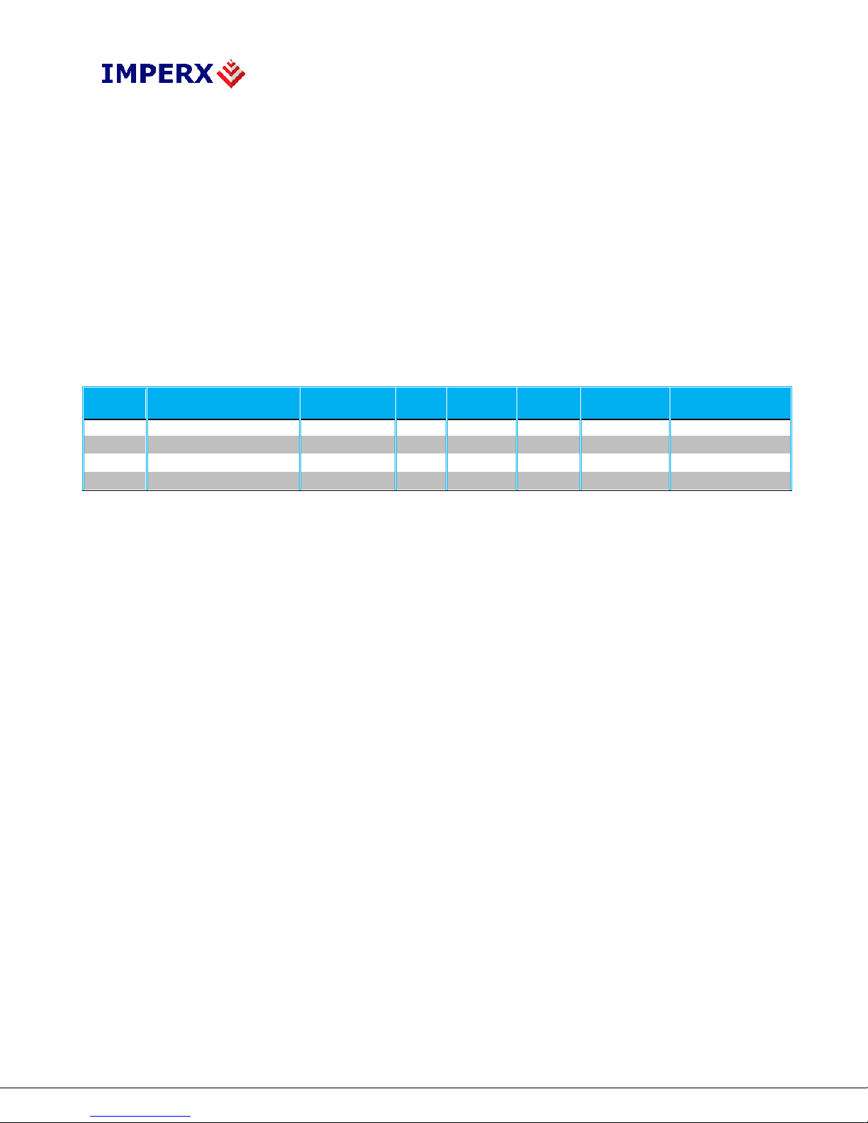
The CHEETAH family list is shown below:
Model
Resolution (H x V)
Speed
Type
Optics
CMOS
Sensor
Supported
Outputs
C4080M
4000x3000
67 fps
Mono
4/3”
ONSEMI
KAC-12040
CLF/CXP*
C4080C
4000x3000
67fps
Color
4/3”
ONSEMI
KAC-12040
CLF/CXP*
C2880M
2832 x 2128
129 fps
Mono
1”
ONSEMI
KAC-6040
CLF/CXP*
C2880M
2832 x 2128
129 fps
Color
1”
ONSEMI
KAC-6040
CLF/CXP*
Table 1.0 Cheetah Family Overview
1.1 GENERAL DESCRIPTION
The CHEETAH cameras are advanced, intelligent, high-resolution, progressive scan, fully
programmable and field upgradeable CMOS cameras. They are built around On
Semiconductors area scan CMOS imagers and are feature rich with a built-in image
processing engine, low noise, and efficient and optimized internal thermal distribution. The
CHEETAH cameras feature a wide range of programmable functions; including, dual video
options, extended dynamic range, exposure control, frame rate control, area of interest,
subsampling, pixel averaging, gain, offset, several triggering options, strobe output control,
transfer function correction, temperature monitoring and user programmable and up-
loadable LUT.
The user can program either a rolling shutter for the widest dynamic range or global shutter
for superior motion capture. The dual video mode allows two independent acquisition
frames (Frame A and Frame B) to be programmed with independent control of exposure
time, area of interest (AOI), subsampling, gain, offset and wide dynamic range parameters.
Additional controls support a variety of ways to seamless switch between frames.
Exposure time for each frame can be controlled using an internal control or controlled by an
external pulse width. Exposure times up to 1 second with 1µs increments in rolling shutter
mode and 5µs increments in global shutter mode are supported. A custom AOI can be
programmed for each acquisition frame and subsampling or pixel averaging capabilities are

CHEETAH Hardware User’s Manual
Imperx, Inc. Rev. 6.2
6421 Congress Ave. 7/7/2015
Boca Raton, FL 33487
+1 (561) 989-0006 10 of 152
also available. Pixel averaging is a unique feature providing reduced noise and improved
signal to noise ratio by blending adjacent pixel information together. Analog gains up to 12
dB (4x) in 12-bit digitization mode and 18 dB (8x) in 10-bit mode are available. Digital gain
controls allow further expansion of the low-end signal with 24dB (15.9x) of additional gain
available. The wide dynamic range capability features multi-integration times within one
frame period compressing bright areas into the available output range and extending the
visible dynamic range up to 100db (global shutter mode only) with up to 3 knee points.
A built-in Gamma correction and user-defined LUT capability optimizes the camera’s
dynamic range even further. Defective and hot pixel corrections can also be applied to
correct for pixels that are over-responding or under-responding. Auto-White Balance
(AWB) is available in color cameras to correct for color temperature. The cameras have a
Camera Link™ interface that includes 8/10/12 bits data transmission with two, four, eight or
ten output taps as well as camera control all on one or two cables. The cameras are fully
programmable via the Camera Link interface. The adaptability and flexibility of the camera
allow it to be used in a wide and diverse range of applications including machine vision,
metrology high-definition imaging and surveillance, medical and scientific imaging,
intelligent transportation systems, aerial imaging, character recognition, document
processing and many more.

CHEETAH Hardware User’s Manual
Imperx, Inc. Rev. 6.2
6421 Congress Ave. 7/7/2015
Boca Raton, FL 33487
+1 (561) 989-0006 11 of 152
1.2 MAIN CHEETAH FEATURES
Global shutter (GS) or rolling shutter (RS)
Monochrome or color
Large 4.7-micron pixels
Excellent near infrared (NIR) sensitivity
Ultra-low fixed pattern noise
Exceptional blooming suppression
Fast frame rates: 129 fps (C2880), 67 fps (C4080)
Dual Video Capability
oIndependent control of resolution, gain, offset, pixel averaging, sub-sampling, area
of Interest (AOI) and WDR for two acquisition frames
oSeamless switching between frames
oManual, auto or triggered frame switching
Extended Dynamic Range (WDR)
o3 knee points, Piece-wise Linear
Color and monochrome pixel averaging (4x and 9x)
Sub-sampling up to 32x
Areas of Interest
Analog and Digital Gain Controls
Offset Control
Three selectable trigger sources: external, pulse generator or computer
Built-in pulse generator
Two programmable output strobes
Auto-white balance: once, static or tracking
Image Enhancements
oHorizontal and vertical flip
Two 12-bit look-up tables: one LUT pre-programmed with gamma 0.45.
Defective pixel correction, hot pixel correction
Two programmable external Inputs and two external outputs.
Camera Link Base, Medium, Full and Deca support
Temperature monitor
Field upgradeable firmware, LUT, DPC, HPC

CHEETAH Hardware User’s Manual
Imperx, Inc. Rev. 6.2
6421 Congress Ave. 7/7/2015
Boca Raton, FL 33487
+1 (561) 989-0006 12 of 152
1.3 CHEETAH SPECIFICATIONS
1.3.1 General Information
A CMOS camera is an electronic device for converting light into an electrical signal.
The camera contains a light sensitive element CMOS (Charge Coupled Device) where
an electronic representation of the image is formed. The CMOS image sensor consists
of a two dimensional array of sensitive elements –silicon photodiodes, also known as
pixels. The photons falling on the CMOS surface create photoelectrons within the
pixels, where the number of photoelectrons is linearly proportional to the light level.
Although the number of electrons collected in each pixel is linearly proportional to the
light level and exposure time, the amount of electrons varies with the wavelength of
the incident light.
1.3.1.1 Rolling and Global Shutter Description
Cheetah C4080 and C2880 cameras support both global and rolling shutter readout
mode. In Global Shutter (GS) mode every pixel starts and stops integration at the same
time. This mode is excellent for clean capture of moving scenes without the need for a
mechanical shutter. When global shutter mode is used, all pixel data is stored in light
shielded regions within each pixel and held there until readout. (Figure 1.0a) In
Rolling Shutter (RS) mode each row of the image sensor is captured at a slightly
different time. (Figure 1.0b) This can cause distortions in the image, if an object is
moving very quickly and the integration time is short with respect to the frame readout
time. In rolling shutter mode, pixels in a row are cleared of charge, allowed to
integrate for the required exposure time and then the entire row is readout. The
resetting of each row ripples through the array and each row is exposed with a slight
time delay (equal to the line readout time) relative to the previous row. In RS mode,
the transistor within each pixel used to provide global shutter capability is used to
provide noise reduction.

CHEETAH Hardware User’s Manual
Imperx, Inc. Rev. 6.2
6421 Congress Ave. 7/7/2015
Boca Raton, FL 33487
+1 (561) 989-0006 13 of 152
Figure 1.0a: Global Shutter Description
Figure 1.0b: Rolling Shutter Description
1.3.1.2 A/D architecture and Blooming Suppression
The On Semiconductor KAC-12040 and KAC-06040 image sensors have an analog to
digital converter on each column and built-in correction circuits that automatically
compensate and correct for fixed pattern noise within the image array. With an A/D
converter on each column of the imaging array, digitization occurs within each row
time rather than within a readout pixel time and this improves noise performance. Two
rows are readout simultaneously (one from the top of the array and one from the

CHEETAH Hardware User’s Manual
Imperx, Inc. Rev. 6.2
6421 Congress Ave. 7/7/2015
Boca Raton, FL 33487
+1 (561) 989-0006 14 of 152
bottom of the array) during one line time readout. The camera takes care of all the
details of re-ordering the lines within frame grabber memory.
The A/D converter architecture allows the user to select between 8, 10 or 12-bit
digitization. The Cheetah C4080 supports both 10 and 12-bit digitization. In 12-bit
digitization mode, the A/D conversion time is longer than the minimum chip readout
time and this reduces maximum frame rates. In 10-bit digitization the A/D conversion
time is reduced increasing the maximum frame rate. The image sensor provides up to
eight LVDS readout banks and the time to readout one line from the image sensor is
less than the time necessary to output the data using Camera Link. The camera
compensates for this mismatch in data output rates by adding additional delay at the
end of each line.
Each pixel within the imaging array has extremely robust anti-blooming suppression
eliminating classic ‘black sun’ artifacts present in other CMOS imaging arrays. The
CMOS readout architecture also eliminates column smearing often seen in traditional
CCD image sensors under extremely bright exposure conditions.
The time interval required for all the pixels, from the entire imager, to be clocked out
of the CMOS is called a frame. To generate a color image a set of color filters (Red,
Green, and Blue) arranged in a “Bayer” pattern, are placed over the pixels. The
starting color is Green. Figure 1.1 shows the CMOS image sensor architecture. Figures
1.2a,b show the camera’s spectral response.

CHEETAH Hardware User’s Manual
Imperx, Inc. Rev. 6.2
6421 Congress Ave. 7/7/2015
Boca Raton, FL 33487
+1 (561) 989-0006 15 of 152
Figure 1.1 –CMOS image sensor architecture
1.3.2 Spectral Sensitivity Curves

CHEETAH Hardware User’s Manual
Imperx, Inc. Rev. 6.2
6421 Congress Ave. 7/7/2015
Boca Raton, FL 33487
+1 (561) 989-0006 16 of 152
Figure 1.2a –KAC-XX040 CMOS mono spectral response.
(Monochrome with the cover glass)
Figure 1.2b –KAC-XX040 CMOS typical color spectral response.
(Color with Microlens and with cover glass)
1.3.3 Bayer Pattern Information
CHEETAH is available with Monochrome or Color CMOS imager. To generate a
color image a set of color filters (Red, Green, and Blue) arranged in a “Bayer”
pattern, are placed over the pixels. The starting color is Green.
1.4 TECHNICAL SPECIFICATIONS
The following Tables describe features and specifications that relate to all
CHEETAH CLF and CXP cameras.
Features / Specifications
C4080/C2880
Shutter Operation
Global or Rolling
Dual Video Operation
Independent Acquisition Frames
Frame Time (Long int.)
up to 1 sec
Subsampling
Up to 32x
Pixel Averaging (color and
mono)
4x, 9x
Wide Dynamic Range
Optional
Auto-White Balance
Yes

CHEETAH Hardware User’s Manual
Imperx, Inc. Rev. 6.2
6421 Congress Ave. 7/7/2015
Boca Raton, FL 33487
+1 (561) 989-0006 17 of 152
Test Image
Static, Dynamic
Mirror image (H Mirror)
Yes
Vertical image (V Mirror)
Yes
Image Overlay
Crosshairs at Optical Center
Defective pixel correction
Static, Dynamic, User DPM,
Hot pixel correction
Static, Dynamic, User HPM
Inputs
1 LVTTL / 1 Opto-coupled
Outputs
1 5v TTL / 1 Opto-coupled
Triggers
Programmable Rising/Falling, De-bounce
Pulse Generator
Yes
In-camera Image Processing
2 LUTs
Camera housing
Aluminum
Supply voltage range
10 V to 15 V DC
Upgradeable firmware
Yes
Upgradeable LUT,DPM, FFC
Yes
Operating
- 40.0 to + 85.0 deg C
Environmental –Storage
- 50.0 to + 90.0 deg C
Vibration, Shock
100G (20-200) Hz XYZ, 1000G
Relative humidity
10% to 90% non-condensing
Table 1.1 Cheetah General Features
Specifications
C4080
C2880
Active image resolution
4000x3000
2832x2128
Active image area (H, V)
18.8mm x 14.1mm
23.5mm Diagonal
13.1mm x 10.0mm
16.65mm Diagonal
Pixel size
4.7 μm
4.7 μm
Video output
Digital, 8/10/12-bit
Output structure
10-Tap
10-Tap
Data clock
80 MHz
80 MHz
Camera interface
DECA/Full/Medium or Base CL
Connector
HDR (26-pin mini CL)
Maximum frame rate
27 fps (12-bit), 67fps (8-bit)
50 fps (12-bit), 129 fps (8-bit)
DR rolling/global
72 (RS) /56 (GS) dB
72 (RS) /56 (GS) dB
Dual Video Frame Control
(FRAME A / FRAME B)
Independent control of
Resolution, Exposure Time,
Gain, Area of Interest,
Subsampling, Pixel Averaging,
Wide Dynamic Range
Independent control of
Resolution, Exposure Time,
Gain, Area of Interest,
Subsampling, Pixel Averaging,
Wide Dynamic Range
Shutter speed
1 us to 1sec (RS),
5s to 1 sec (GS)
1 us to 1 sec (RS),
5sto 1 sec (GS)
Area of Interest
One per Frame
One per Frame
Analog gain
0 to 12dB (12-bit),
0 to 18dB (8 & 10-bit)
0 to 12dB (12-bit)
0 to 18dB (8 & 10-bit)

CHEETAH Hardware User’s Manual
Imperx, Inc. Rev. 6.2
6421 Congress Ave. 7/7/2015
Boca Raton, FL 33487
+1 (561) 989-0006 18 of 152
Digital gain
0 to 24dB
0 to 24dB
Black level offset
0 to 2048, 1/step
0 to 2048 1/step
User LUT
2 LUTs: Gamma, User LUT
Dual Frame Switching
Control
Manual, Auto, External Trigger
Manual, Auto, External
Trigger
Hardware trigger
Asynchronous
Asynchronous
Strobe Modes
Programmable Width, Delay
, Programmable Width, Delay
Trigger Sources
External , Pulse Generator,
Computer
External, Pulse Generator,
Computer
Trigger features
Rising/Falling edge, De-glitch,
Delay, Strobe
Rising/Falling edge, De-glitch,
Delay, Strobe
Size (W x H x L) - CLB
(72.0 x 72.0 x 39.8) mm
Weight
384 g
TBD
Lens Mount
F-Mount, C-Mount, 4/3” format
C-Mount–1” format
Power:
12V / 0.34 A
TBD
Table 1.2 Cheetah C2880, C4080 Camera Specifications.
1.5 CAMERA CONNECTIVITY
1.5.1 CLF (Full) - Camera Link (CL) Output
The interface between the CHEETAH cameras and outside equipment is done via 2
connectors and one LED, located on the back panel of the camera –Figure 1.3.
1. Two camera outputs –standard Full Camera Link Mini connectors provides data,
sync, control, and serial interface.
2. Male 12-pin Power Connector –provides power and I/O interface.
3. USB type B programming/SPI connector.
4. Status LED –indicates the status of the camera –refer to Status LED section.
5. Model / Serial Number –shows camera model and serial number.

CHEETAH Hardware User’s Manual
Imperx, Inc. Rev. 6.2
6421 Congress Ave. 7/7/2015
Boca Raton, FL 33487
+1 (561) 989-0006 19 of 152
Figure 1.3 –CLF Camera back panel / Deca, Full, Medium or Base
1.5.2 Camera Link Full Signal Mapping
Camera data output is compliant with Deca (80-bit), Full (64-bit), Medium (48-bit)
and Base (24-bit) Camera Link standard, up to 80 data bits, 4 sync signals (LVAL,
FVAL, DVAL and User Out), 1 reference clock, 2 external inputs CC1, CC2 and a
bi-directional serial interface. The camera link output connectors are shown in
Figure 1.4a and 1.4b, and the corresponding bit and port mapping is described
below.
1
14
13
26
Figure 1.4a –CLF Camera output connector 1
Cable Name
Pin
CL Signal
Type
Description
Base Wire
1
12 VDC Power
Power
Power Base
Base Wire
14
Power Return
Ground
Ground
- PAIR 1
2
- X 0
LVDS - Out
Camera Link Channel Tx
+ PAIR 1
15
+ X 0
LVDS - Out
Camera Link Channel Tx
- PAIR 2
3
- X 1
LVDS - Out
Camera Link Channel Tx
+ PAIR 2
16
+ X 1
LVDS - Out
Camera Link Channel Tx
- PAIR 3
4
- X 2
LVDS - Out
Camera Link Channel Tx
+ PAIR 3
17
+ X 2
LVDS - Out
Camera Link Channel Tx
- PAIR 4
5
- X CLK
LVDS - Out
Camera Link Clock Tx

CHEETAH Hardware User’s Manual
Imperx, Inc. Rev. 6.2
6421 Congress Ave. 7/7/2015
Boca Raton, FL 33487
+1 (561) 989-0006 20 of 152
+ PAIR 4
18
+ X CLK
LVDS - Out
Camera Link Clock Tx
- PAIR 5
6
- X 3
LVDS - Out
Camera Link Channel Tx
+ PAIR 5
19
+ X 3
LVDS - Out
Camera Link Channel Tx
+ PAIR 6
7
+ SerTC
LVDS - In
Serial Data Receiver
- PAIR 6
20
- SerTC
LVDS - In
Serial Data Receiver
- PAIR 7
8
- SerTFG
LVDS - Out
Serial Data Transmitter
+ PAIR 7
21
+ SerTFG
LVDS - Out
Serial Data Transmitter
- PAIR 8
9
- CC 1
LVDS - In
User Selectable Input
+ PAIR 8
22
+ CC 1
LVDS - In
User Selectable Input
+ PAIR 9
10
+ CC2
LVDS - In
User Selectable Input
- PAIR 9
23
- CC2
LVDS - In
User Selectable Input
- PAIR 10
11
N/C
N/C
N/C
+ PAIR 10
24
N/C
N/C
N/C
+ PAIR 11
12
N/C
N/C
N/C
- PAIR 11
25
N/C
N/C
N/C
Base Wire
13
Power Return
Ground
Ground
Base Wire
26
12 VDC Power
Power
Power Base
Table 1.3a CLF Camera Output Connector 1 –Signal Mapping
1
14
13
26
Figure 1.4b –CLF Camera output connector 2
Cable Name
Pin
CL Signal
Type
Description
Base Wire
1
12 VDC Power
Power
Power Base
Base Wire
14
Power Return
Ground
Ground
- PAIR 1
2
- Y 0
LVDS - Out
Camera Link Channel Tx
+ PAIR 1
15
+ Y 0
LVDS - Out
Camera Link Channel Tx
- PAIR 2
3
- Y 1
LVDS - Out
Camera Link Channel Tx
+ PAIR 2
16
+ Y 1
LVDS - Out
Camera Link Channel Tx
- PAIR 3
4
- Y 2
LVDS - Out
Camera Link Channel Tx
+ PAIR 3
17
+ Y 2
LVDS - Out
Camera Link Channel Tx
- PAIR 4
5
- Y CLK
LVDS - Out
Camera Link Clock Tx
+ PAIR 4
18
+ Y CLK
LVDS - Out
Camera Link Clock Tx
- PAIR 5
6
- Y 3
LVDS - Out
Camera Link Channel Tx
+ PAIR 5
19
+ Y 3
LVDS - Out
Camera Link Channel Tx
This manual suits for next models
2
Table of contents
Other Imperx Color Camera manuals