manuals.online logo
Brands
  1. Home
  2. •
  3. Brands
  4. •
  5. Impex
  6. •
  7. Home Gym
  8. •
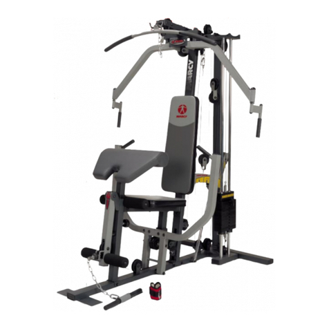
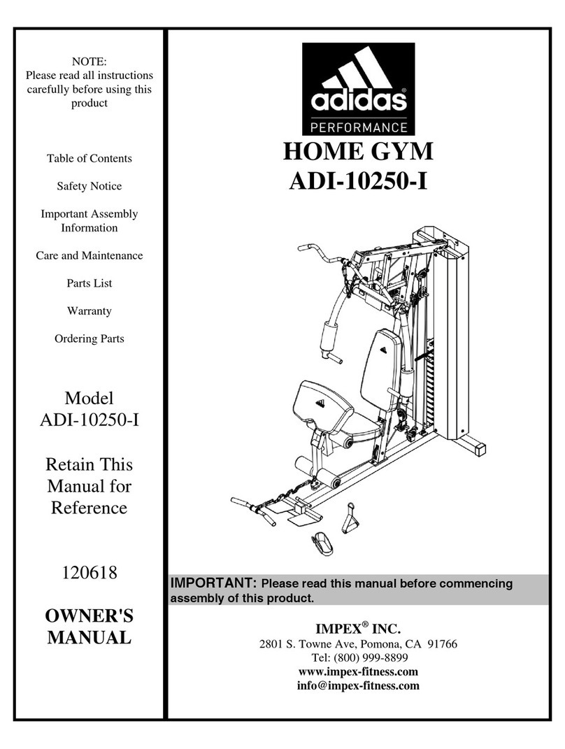
  9. Impex PowerhouseWM 1400 Use and care manual

Impex PowerhouseWM 1400 Use and care manual

United
States
Patent
US006685607B1
(12) (10)
Patent
N0.:
US
6,685,607
B1
Olson
(45)
Date
of
Patent:
Feb.
3,
2004
(54)
EXERCISE
DEVICE
WITH
RESISTANCE
5,685,810
A
11/1997
Chung
MECHANISM
HAVING
A
PIVOTING
ARM
5,776,040
A
7/1998
Webb
et
91
AND
A
RESISTANCE
MEMBER
OTHER
PUBLICATIONS
(75)
Inventor;
Michael
L,
Olson,
Logan,
UT
(US)
OWner’s
Manual
for
Impex
Fitness
Products,
Powerhouse
Home
Gym
WM
1400,
Revised
Jun.
30,
2000.
(73)
Assignee:
Icon
IP,
Inc.,
Logan,
UT
(US)
Website
page
of
Impex,
dated
Nov.
6,
2001.
Webiste
pages
(16
pp.)
for
Impex
dated
Dec.
11,
2001.
(
*
)
Notice:
Subject
to
any
disclaimer,
the
term
of
this
_ _ _ _
patent
is
extended
or
adjusted
under
35
Primary
Examwer—Nlcholas
D‘
Lucchesl
US'C'
154(k))
by
0
days'
Assistant
Examzner—L
Amerson
(74)
Attorney,
Agent,
or
Firm—Workman
Nydegger;
David
B.
D
b h
(21)
Appl.
N0.:
10/340,562
we“
ac
57
ABSTRACT
(22)
Filed:
Jan.
10,
2003
( )
7
An
exercise
device
is
con?gured
to
provide
adjustable
(51)
Int.
Cl.
..............................................
..
A63B
26/00
resistance
to
the
motion
of
a
user
exercising
With
the
(52)
US‘
Cl-
~~~~
~~
482/142;
482/148;
482/907;
exercise
device.
The
exercise
device
includes
a
frame
that
at
_
482/908
least
partially
supports
an
operable
assembly.
Cooperating
Fleld
of
Search
. . . . . . . . . . . . . . . . . . . . . . . . . . . . . . .
..
the
Operable
assembly
is
a
resistance
assembly
482/907,
908
provides
a
resistance
adjustable
by
the
user of
the
exercise
_
device.
The
resistance
assembly
includes
an
actuating
(56)
References
Clted
assembly
that
engages
With
a
pivoting
arm.
The
actuating
Us
PATENT
DOCUMENTS
assembly
includes
a
handle
mechanism
that
is
simple
to
operate
and
enables
a
user
to
easily
select a
desirable
4,275,882
A
6/1981
Grosser
et
91-
resistance
level.
A
connecting
member
of
the
actuating
474267077
A
1/1984
Becker
assembly
extends
from
the
handle
mechanism
to
a
resistance
4,540,171
A
9/1985
Clark
et
a1‘
member.
Movement
of
the
operable
assembly
moves
the
2
“K1986
Brf’wn
arm
toWard
a
?xed
end
of
the
resistance
member.
The
, ,
/1987
Minkow
. . .
4898
381
A
21990
Gordon
connectmg
member
temporarily
lengthens
the
resistance
4:974j838
A
12/1990
sollenberger
member,
While
the
resistance
member
inhibits'such
move
5’031’905
A
7/1991
Walsh
ment
and
provides
resistance
to
the
exercismg
user’s
5,316,534
A
5/1994
Dalebout
et
a1.
motion.
5,344,374
A
9/1994
Telle
5,527,245
A
6/1996
Dalebout
et
a1.
22
Claims, 12
Drawing
Sheets
U.S.
Patent
Feb.
3,
2004
Sheet
1
0f
12
US
6,685,607
B1
U.S.
Patent
Feb.
3,
2004
Sheet
2
0f
12
US
6,685,607
B1
U.S.
Patent
Feb.
3,
2004
Sheet
3
0f
12
US
6,685,607
B1
U.S.
Patent
Feb.
3,
2004
Sheet
4
0f
12
US
6,685,607
B1
U.S.
Patent
Feb.
3,
2004
Sheet
5
0f
12
US
6,685,607
B1
5A
5A
158
152
U.S.
Patent
Feb.
3,
2004
Sheet
6
6f
12
US
6,685,607
B1
154
130\
154
130\
152
152 150
150
156
156
134
3
Q
/15a
7/
Q
5
A
<
7"r\12e
s
140
/
160
15a\/
1as\
A
Fig.
58
Fig.
5A
U.S.
Patent
Feb.
3,
2004
Sheet
7
0f
12
US
6,685,607
B1
|
~r__..-_;T__________.-
/
U.S.
Patent
Feb.
3,
2004
Sheet
8
0f
12
US
6,685,607
B1
124
U.S.
Patent
Feb.
3,
2004
Sheet
9
6f
12
1k
0
0
00000
120
0000000
132
n
o
‘9
O
168
164
114a
142
166
O
0
0
144
Fig. 8
US
6,685,607
B1
124
20a
U.S.
Patent
Feb.
3,
2004
Sheet
10
0f
12
US
6,685,607
B1
11
130
112
o
/
0
110
120
000
a?»
00
o
168
Z
%
00
164
g
o
112
°
0
114
(‘IO/,1”
142
"
124
A
A
°
-=l%
0
20a
0
O
O
144
Fig.
9
U.S.
Patent
Feb.
3,
2004
Sheet
11
0f
12
US
6,685,607
B1
Fig.
10
U.S.
Patent
Feb.
3,
2004
Sheet
12
0f
12
US
6,685,607
B1
US
6,685,607
B1
1
EXERCISE
DEVICE
WITH
RESISTANCE
MECHANISM
HAVING
A
PIVOTING
ARM
AND
A
RESISTANCE
MEMBER
BACKGROUND
OF
THE
INVENTION
1.
The
Field
of
the
Invention
The
present
invention
generally
relates
to
exercise
devices
and
more
generally
to
methods,
systems,
and
devices
for
selectively
modifying
a
resistance
level
of
an
exercise
device.
2.
The
Relevant
Technology
In
recent
years,
there
has
been
a
trend
toWards
the
use of
exercise
equipment,
Whether
it
is
at
a
gym
or
at
home.
Although
gym
exercise
equipment
provides
many
bene?ts
to
an
exercising
user,
it
is
typically
expensive
to
become
a
member
of
the
gym
and
usually
time
consuming
and
incon
venient
to
exercise
at
the
gym.
Many
individuals
are
turning
to
home
exercise
equipment
to
obtain
the
health
bene?ts
associated
With
daily
exercising.
Although
home
exercise
equipment
is
more
convenient
to
use,
in
many
instances
the
devices
are
cumbersome
and
dif?cult
to
use.
For
instance,
many
multi-gym
exercise
devices
use
free
Weights
or other
heavy
Weights
to
provide
resistance
during an
exercise
regime.
These
Weights
make
positioning
and
subsequent
movement
of
the
exercise
device
dif?cult.
Typically,
once
a
multi-gym
device
has
been
set-up
in
one
position,
it
Will
remain
there
for a
signi?cant
amount
of time
Without
being
moved.
When
the
device
is
to
be
moved,
the
oWner
must
spend
a
long
period
to
dismantle
the
device,
move
the
parts
to
the
neW
position
Within
the
home,
and
reassemble
the
exercise
device.
Additionally,
use of
such
a
multi-gym
device
requires
the
user
to
set
aside
a
signi?cant
amount
of space
Within
the
user’s
home.
This
reduces
the
livable
space
Within
the
home
and
typically
requires
that
an
area
of
the
home
be
dedicated
to
the
performance
of
exercise
regimes.
It
Would
be
preferential
to
have
an
exercise
device
that
is
mobile
and
capable
of
being
repositioned
to
alloW
the
user
to
utiliZe
the
space
Within
his
or
her
home.
Typical
exercise
devices
use
Weights
to
provide
resistance
to
an
exercising
user.
The
selection
of
Weights
may
be
dif?cult
to
achieve
before
and
during
an
exercise
regime.
Additionally,
selection
of
a
particular
resistance
is
limited
to
the
incremental
Weights
provided With
the
exercise
device.
For
instance, the
adjustability
of
the
exercise
device
to
a
particular
Weight
is
often
limited
by
the
minimum
numerical
Weight
value
of
the
Weights
included
With
the
exercise
device.
It
Would
be
bene?cial
to
have
an
exercise
device
Where
very
small incremental
changes
in
the
exercise
resis
tance
Were
possible.
In
addition
to
the
above,
the
adjustability
of
the
exercise
device
limits
the
usability
of
the
exercise
device.
Many
exercise
devices
require
removal
of pins
and
repositioning
of
Weights
to
vary
the
resistance
applied
to
an
exercising
user.
This
may
be
time
consuming
and
dif?cult
to
achieve
depending
the
particular
con?guration
of
the
exercise
device.
Over
time,
there
is
a
high
likelihood
that
the
pins
associated
With
the
exercise
device
Will
become
lost,
thereby
preventing
a
user
exercising
using
the
exercise
device.
Some
exercise
devices attempt
to
overcome
the
limita
tions
associated
With
the
use
of
heavy
Weights
to
provide
resistance
to
an
exercising
user.
These
exercising
devices
may
utiliZe
gas
or
?uid
cylinders
that
provide
a
resistance as
a
user
exercises
upon
the
exercise
device.
A
gas
or
?uid
15
35
45
55
65
2
Within
an
interior
chamber
of
the
cylinder
may
?oW
through
a
variable
restriction
member
that
may
govern
the
resistance
applied
by
the
cylinder.
For
instance,
When
the
restriction
member
alloWs
a
high
?oW
rate
of
?uid
therethrough,
the
resistance
applied
by
the
cylinder
is
loW.
Similarly,
When
the
restriction
member
alloWs
a
loW
?oW
rate,
the
cylinder
provides
a
high
resistance
to
the
exercising
user.
Although
bene?cial
in
reducing
the
overall
Weight
of
an
exercise device,
and
thereby
enabling
repositioning
of an
exercise
device
in a
simple
and
efficient
manner,
the
effec
tiveness
and
long-term
usage
of
certain
gas
cylinders
may
be
limited.
Over
time,
the
gas
or
?uid
contained
Within
the
cylinder
may
leak.
This
can
result
in
the
cylinder
providing
a lesser
amount
of
resistance
than
Was
possible
When
the
cylinder
Was
neWly
manufactured.
Based
upon
the
above,
it
Would
bene?cial
to
have
an
exercise
device
that
is
simple
to
position
through
reducing
the
overall
Weight
of
the
exercise device,
While
providing
a
resistance
mechanism
that
is
easily
adjustable,
While
main
taining
the
level
of
resistance
associated
With
the
exercise
device
over
a
long
period.
BRIEF
SUMMARY
OF
THE
INVENTION
The
present
invention
generally
relates
to
an
exercise
device
that
is
capable
of
being
readily
adjustable
to
provide
variable
resistance
to
an
exerciser
using
the
exercise
device.
The
adjustable
resistance
of
the
exercise
device
may
be
easily
and
ef?ciently
modi?ed
through
simply
operating
a
handle
mechanism,
repositioning
the
handle
mechanism
to
a
neW
position,
and
subsequently
releasing
the
handle
mecha
nism
to
set
the
resistance
for
the
exercise
device.
This
provides
an
exercise
device
that
may
be
easily
adjusted
Without
the
need
to
remove
pins,
reposition
a
resistance
mechanism
or
Weights
upon
the
device, or
reposition
a
pin
or
other
fastener
removed
from
the
exercise
device.
Additionally,
the
exercise
device
is
adapted
to
provide
a
resistance
assembly
that
has
compact
characteristics,
thereby
limiting
the
overall
space
required
or
associated
With
the
exercise
device.
According
to
one
embodiment
of
the
present
invention,
the
exercise
device
includes
a
frame
that
at
least
partially
supports
at
least
one
exercise
mechanism,
such
as a
leg
exerciser
or
(ii)
overhead
handles
that
may
be used
to
perform
exercises.
Aconnecting
system,
such
as
a
cable
and
pulley
system
connects
the
exercise
mechanism
to
a
resis
tance
assembly
that
is
coupled
to
the
frame.
The
resistance
assembly
provides
resistance
to
the
motion
of
the
exercise
mechanisms
and hence
resistance
to
the
motion
of
the
user
exercising
With
the
exercise
device.
The
resistance
assembly
includes:
a
pivoting
arm
pivotally
coupled
to
the
frame;
(ii)
an
actuating
assembly
that
engages
the
pivoting
arm;
and
(iii)
at
least
one
extendible,
resilient
resistance
member.
Resistance
levels
of
the
exercise
device
may
be
selected
as
a
user
moves
the
actuating
assembly
relative
to
the
pivoting
arm.
The
closer
the
actuating
assembly
is
to
the
pivoting
axis
of
the
arm,
the
loWer
the
level
of
resistance
provided
to
the
user’s
motion.
Inversely,
the
further
the
actuating
assembly
is
from
the
pivoting
axis
of
the
arm,
the
higher
the
level
of
resistance
provided
to
the
user’s
motion.
In
one
embodiment,
the
actuating
assembly
couples
to
a
resilient
resistance
member
such
as
a
rubber
band
or
spring
that
is
coupled
to
the
frame.
The
resilient
member
resists
movement
of
the
actuating
assembly and
consequently
of
the
pivoting
arm.
By
employing
the
resilient
member,
the
use of
a
shock
is
avoided.
Furthermore,
the
resilient
member
US
6,685,607
B1
3
is
strategically
oriented
so
that
the
resistance
assembly
is
compact
and
highly
ef?cient.
The
actuating
assembly
includes
a
handle
mechanism
that
is
simple
to
operate
and
enables
a
user
to
easily
select a
desirable
resistance
level.
The
handle
mechanism
includes
a
?xed
member
and
a
moveable
member
pivotally
connected
to
the
?xed
member
and
biased
from
the
?xed
member.
Disposed
at
an
end
of
the
moveable
member
is
an
engage
ment
member
that
is
adapted
to
cooperate
With
at
least
one
aperture
formed
in
the
pivoting
arm.
As
a
user
overcomes
the
biasing
force
betWeen
the
?xed
member
and
the
move
able
member,
the
engagement
member
is
removed
from
an
aperture
to
alloW
movement
of
the
handle
mechanism
rela
tive to
the
arm.
When
a
neW
resistance
level
is
selected,
such
as
When
the
handle
mechanism
has
been
moved
to
a
selected
position
on
the
arm,
a
user
may
alloW
the
biasing
force
to
move
the
moveable
member
relative
to
the
?xed
member
to
position
the
engagement
member
Within
another
aperture.
This
positioning
of
the
engagement
member
Within
another
aperture
locks
the
position
of
the
handle
mechanism
and
hence
sets
the
selected
resistance
level.
Extending
from
the
handle
mechanism
is
a
connecting
member.
The
connecting
member
cooperates
With
the
resil
ient
resistance
member
and
functions
to
move
a
moveable
end
of
the
resistance
member
as a
user
moves
the
operable
mechanism.
The
position
of
the
handle
mechanism
upon
the
pivoting
arm
and
the
amount
that
the
connecting
system
is
moved
governs
the
amount
of
movement
of
the
resistance
member’s
moveable
end.
With
the
handle
mechanism
close
to
the
pivotal
axis
of
the
arm,
the
amount
of
movement
of
the
resistance
member’s
moveable
end
is
small
and
so
the
level
of
resistance
is
small.
Similarly,
With
the
handle
mechanism
being
distant
from
the
pivotal
axis
of
the
arm,
the
amount
of
movement
of
the
resistance
member’s
move
able
end
is
large
and
so
the
level
of
resistance
is
large.
A
variety
of
resistance
selections
in
betWeen
are also available.
According
to
another
embodiment
of
the
present
invention,
the
exercise
device
includes
a
motoriZed
resis
tance
assembly.
The
resistance
assembly
includes
an
arm
assembly
pivotally
connected
to
a
frame
of
the
exercise
device.
The
arm
assembly
includes
an
arm
With
one
or
more
arced
surfaces
that
cooperate
With
a
connecting
assembly
of
the
exercise
device.
A
cross
member
of
the
connecting
assembly
slides
along
the
arced
surfaces
as a
motor
rotates
a
drive
member
connected
to
the
arm.
As
the
cross
member
moves
along
the
drive
member,
the
position
of
at
least
one
connecting
member
relative
to
at
least
one
resistance
mem
ber
changes.
The
position
of
the
cross
member
and/or
the
connecting
member
de?nes
the
resistance
level
of
the
resis
tance
assembly.
These
and
other
objects
and
features
of
the
present
invention
Will
become
more
fully
apparent
from
the
folloW
ing
description
and
appended
claims,
or
may
be
learned
by
the
practice
of
the
invention
as
set
forth
hereinafter.
BRIEF
DESCRIPTION
OF
THE
DRAWINGS
To
further
clarify
the
above and
other
advantages
and
features
of
the
present
invention,
a
more
particular
descrip
tion
of
the
invention
Will
be
rendered
by
reference
to
speci?c
embodiments
thereof
that
are
illustrated
in
the
appended
draWings.
It
is
appreciated
that
these
draWings
depict
only
typical
embodiments
of
the
invention
and
are
therefore
not
to
be
considered
limiting
of
its
scope.
The
invention
Will
be
described
and
explained
With
additional
speci?city
and
detail
through
the
use
of
the
accompanying
draWings
in
which:
10
15
25
35
45
55
65
4
FIG.
1
illustrates
a
perspective
vieW
of
an
exercise
device
in
accordance With
one
embodiment
of
the
present
inven
tion;
FIG.
2A
illustrates
a
side
vieW
of
the
exercise
device
of
FIG.
1
With
a
second
exercise
mechanism
in
an
exercising
position;
FIG.
2B
illustrates
a
side
vieW
of
the
exercise
device
of
FIG.
1
With
a
second
exercise
mechanism
in a
storage
position;
FIG.
3
illustrates
a
perspective
vieW
of
a
portion
of
a
resistance
assembly
of
the
exercise
device
of
FIG.
1;
FIG.
4
illustrates
a
perspective
vieW
of
a
portion
of an
actuating
assembly
of
the
exercise
device
of
FIG.
1;
FIGS.
5A
and
5B
illustrate
a
partial
cross-sectional
vieW
of
the
portion
of
the
actuating
assembly
of
FIG.
4
demon
strating
the
selective
movement
of
the
handle
in
order
to
selectively
move
the
actuating
assembly;
FIG.
6
illustrates
a
partial
cross-sectional
vieW
of
a
resistance
assembly
of
the
exercise
device of
FIG.
1
With
the
actuating
assembly
located
at
a
?rst
position
closest
to
a
pivotal
axis
of an
arm
of
the
resistance
assembly;
FIG.
7
illustrates
a
partial
cross-sectional
vieW
of
the
resistance
assembly
of
the
exercise
device
of
FIG.
1
as
an
exercise
mechanism
is
manipulated;
FIG.
8
illustrates
a
partial
cross-sectional
vieW
of
the
resistance
assembly
of
the
exercise
device of
FIG.
1
With
the
actuating
assembly
located
at
a
second
position
furthers
from
a
pivot
axis
of
an
arm
of
the
resistance
assembly;
FIG.
9
illustrates
a
partial
cross-sectional
vieW
of
the
resistance
assembly
of
the
exercise
device
of
FIG.
1
as
an
exercise
mechanism
is
manupulated;
FIG.
10
illustrates
a
perspective
vieW
of
one
or
more
secondary
support
members
that
facilitate
attachment
of
one
or
more
additional
resistance
members
according
to
another
aspect
of
the
invention;
and
FIGS.
11A
and
11B
illustrates
partial
cross-sectional
vieWs
of
a
resistance
assembly
featuring
a
motoriZed
resis
tance
member
according
to
another
aspect
of
the
invention.
DETAILED
DESCRIPTION
OF
THE
PREFERRED
EMBODIMENTS
The
present
invention
generally
relates
to
an
exercise
device
that
has
an
adjustable
resistance
assembly
that
pro
vides
resistance
to
an
exercising
user
as
he
or
she
manipu
lates
the
exercise
mechanisms
of
the
exercise
device.
This
resistance
assembly
provides
a
simple
and
ef?cient
manner
by
Which
the
user
may
select
different
resistances,
Without
the
possibility
of
loosing
pins
or
other
elements
that
are
typically
used
to
select
a
particular
resistance.
The con?gu
ration
of
the
resistance
assembly
is
compact,
thereby
limit
ing
the
overall
space
required
or
associated
With
the
exercise
device.
With
reference
noW
to
FIG.
1,
depicted
is
one
con?guration
of an
exercise
device
according
to
one
aspect
of
the
present
invention.
Exercise
device
10
comprises:
a
frame
11;
(ii)
at
least
one
exercise
mechanism
(such
as
over
head
handle
pull
doWn
mechanism
14
and
leg
exercising
mechanism
16);
(iii)
a
resistance
assembly
12
that
couples
to
frame
11;
and
(iv)
a
connecting
mechanism
18
that
couples
the
at
least
one
exercise
mechanism,
e.g.,
mechanisms
14 and 16
to
the
resistance
assembly
12.
Resistance
assembly 12
controls
the
amount
of
resistance
encountered
by
a
user
exercising
With
exercise
mechanisms
14
and
16.
With
reference
noW
to
FIGS.
1,
2a, 2b,
and
3,
resistance
assembly
12
includes:
a
pivoting
arm
110
pivotally
US
6,685,607
B1
5
coupled
to
frame
11;
(ii)
an
actuating
assembly
112
that
engages
pivoting
arm
110;
and
(iii)
at
least
one
and
prefer
ably
?rst
and
second
extendible,
resilient
resistance
mem
bers
114a, 114n.
Connecting
mechanism
18
of
FIGS.
1—10
is
a
cable
and
pulley
system
or
assembly
that
couples
the
at
least
one
exercise
mechanism,
e.g.,
mechanisms
14
and 16
to
the
resistance
assembly
12,
such
that
the
second
end
of
arm
110
cooperates
With
the
exercise
mechanism
so
that
movement
of
the
exercise
mechanism
moves
the
arm
110.
Frame
11,
cable
and
pulley
system
18,
and
exercise
mechanisms
14,
16
Will
noW
be
discussed
in
additional
detail.
Frame
11
comprises
a
base
44;
and
(ii)
?rst
and
second
upstanding
members
42a,
42b
extending
upWardly
from
base
44.
Base
44
may
include
one
or
more
Wheels
46
that
may
aid
With
positioning
exercise
device
10.
Various
portions
of
frame
11
may
be
holloW
so
that
connecting
system 18
may
be
at
least
partially
disposed
therein.
Cable
and
pulley
system
18
comprises
at
least
one
and
preferably
a plurality
of
cables
and
at
least
one
and
prefer
ably
a plurality
of
pulley
stations.
In
the
embodiment
shoWn,
system 18
comprises
a
primary
cable
20a
that
extends
from
pulley
station
22a
to
pulley
station
22b
and
passes
through
resistance
assembly
12.
Pulley
stations
22a
and
22b
are
mounted
to
frame
11
by
supports
28a
and
28b.
Secondary
cables
20b
and
20c
couple
to
respective
ends
of
primary
cable
20a
and
extend
upWardly
and
through
respective
pulley
stations
22c
and
22d.
Tertiary
cable
20d
couples
to
leg
exercise
mechanism
16 and
couples
to
at
least
one
of
the
ends
of
primary
cable
20a,
preferably
forking
so
as
to
couple
to
both
ends
of
cable
20a.
Each
end
of
cable
20a,
and
the
terminating
ends
of
cables
20b—20c,
includes
a
stop
30
that
prevents
the
end
of
the
cable
passing
through
the
respective
pulley
stations
22a—22d
toWard
resistance
assembly 12
during
performance
of
an
exercise.
Cable
of
the
present
invention
may
be
comprised
of
metallic
material,
rope,
string,
or
other
materials
that
are
capable of
functioning
as
described
herein.
Each
pulley
station
22a—22d
includes
a
pivoting
member
24a—24d,
respectively,
that
supports
one
or
more
pulleys
26.
As
a
user
moves
?rst
exercise
mechanism
14,
for
instance,
pivotal
member
24d
moves
to
position
pulley
26
so
that
cable
20d
slides
along
pulley
26.
Disposed
at
a
top
of
frame
11
is
?rst
exercise
mechanism
14.
The
?rst
exercise
mechanism
14
enables
an
exercising
user
to
perform
exercises
using
the
user’s
arms.
Handles
58
are
attached
to
respective
cables
20b,
20c.
The
pivoting
properties
of pulley
stations
22a—22d
enable
the
user
to
move
handle
58
relative
to
frame
11,
While
cable
20a—c
remains
in
engagement
With
respective
pulley
26.
With
continued
reference
to
FIG.
2A,
mounted
to
base
44
is
second
exercise
mechanism
16
is
shoWn
coupled
to
pivoting
bench
assembly
19.
Bench
assembly 19
includes
an
elongate
member
70
pivotally
mounted
to
base
44 by
Way
of
a
bracket
72.
This
bracket
72
alloWs
elongate
member
70
to
be
positioned
in
an
exercising
position
Where
elongate
member
70
is
generally
parallel
to
a
surface
upon
Which
exercise
device
10
is
disposed
and
a
storage
position,
shoWn
in
the
partial
vieW
of
exercise
device
10
depicted
in
FIG.
2B,
Where
elongate
member
70
is
generally
perpendicular
to
a
surface
upon
Which
exercise
device
10
is
disposed.
Bracket
72
may
be
secured
in
either
the
exercising
position or
the
storage
position
through
use
of
a
locking
member
78
that
passes
through
bracket
72
to
cooperate
With
extension
member
Cooperating
With
elongate
member
70
is
a seat
90
and
a
backrest
92
upon
Which
a
user
may
sit
or
incline
as
he
or
she
10
15
25
35
45
55
65
6
uses
?rst
exercise
mechanism
14
and/or
second
exercise
mechanism
16.
The
seat
90
may
be
slidably
positioned
upon
elongate
member
70
to
accommodate
user of
various
siZes.
The
backrest
92
may
be
inclined
and
optionally
cooperate
With
frame
11.
Also
attached
to
elongate
member
70
at
a
location
distant
from
bracket
72
is
exercise
mechanism
16
in
the
form
of
a
leg
developer
assembly
having
a
leg
lever
82
pivotally
coupled
to
a
leg
lever
support
84.
The
leg
lever
82
connects
to,
in
one
embodiment,
resistance
assembly
12
by
Way
of
pulley
station
22a
and
cable
20d.
Resistance
assembly
12
Will
noW
be
described
in
addi
tional
detail.
As
illustrated
in
FIG.
1,
resistance
assembly
12
is
at
least
partially
enclosed
by
a
housing
32.
Discussion
of
housing
32
Will
be
made
With
respect
to
one
side
of
housing
32,
hoWever,
it
is
contemplated
that
the
other
side
of
housing
32
is
generally
a
mirror
image
of
the
described
housing.
The
housing
32
includes
a
hole
34
that
enables
a
user
to
access
resistance
assembly
12.
The
housing
32
may
optionally
include
one
or
more
indicia
36
that
may
be used
With
resistance
assembly
12
to
identify
the
particular
level
of
resistance
at
Which
resistance
assembly 12
may
be
set.
The
housing
32
may
optionally
include
cable
guides
38
that
may
receive
cables
20b
and
20c
and
securely
retain
the
same
therein.
With
continued
reference
to
FIGS.
1—3,
resistance
assem
bly
12
includes
a
resistance
arm
110
that
is
pivotally
coupled
to
frame
11
and
is
movably
coupled
to
actuating
assembly
112.
The
resistance
arm
110
is
pivotally
attached
to
a
mounting
member
120
(FIG.
4)
of
frame
11.
The
second
end
122
of
resistance
arm
110
moves
as a
user
exercises
using
exercise
device
10.
Arm
110
is
depicted
as
having
a
gener
ally
curved
pro?le.
HoWever,
one
skilled
in
the
art
may
appreciate
that
arm:
110
may
have
various
other
con?gura
tions
to
perform
the
functions
described
herein.
A
?rst
end
118
of
arm
110
is
pivotally
coupled
to
frame
11.
A
second
end 122
of
arm
110
has
a
pulley
assembly
124
therein
that
receives
cable
20a
about
its
one
or
more
pulleys
125a—125n,
Which
are
mounted
to
second
end
122
by
one
or
more
brackets
127a
and
12711.
Cable
20a
extends
from
pulley
station
22b
to
pulley
station
22a
after
being
received
by
one
or
more
intermediate
pulleys
128a—128n,
pulley
assembly
124,
and
a
base
pulley
assembly
144
that
is
mounted
to
base
44 by
bracket
146.
In
the
illustrated
con?guration,
cable
20a
extends
from
pulley
station
22b,
through
one
or
more
of
intermediate
pulleys
128a—128n
mounted
to
frame
11.
This
cable
20a
continues
from
intermediate
pulleys
128a—128n
to
be
received
at
pulley
assembly
124
and
associated
the
one
or
more
pulleys
125a—125n.
Extending
from
pulley
assembly
124,
cable
20a
is
received
by
a
base
pulley
assembly
144
that
also
includes
one
or
more
pulleys
129a—129n.
This
cable
20a
then
optionally
repeatedly
extends
from
pulley
assembly
144
to
pulley
assembly
124
and
then
passes
to
other
similar
intermediate
pulleys
128a—128n,
before
termi
nating
at
pulley
station
22a.
As
an
exerciser
moves
both
of
the
handles
of
?rst
exercise
mechanism
14
(FIG.
1),
for
example,
the
available
length
of
cable
20a
extending
betWeen
pulley
assembly
124
and
pulley
assembly
144
shortens.
This
shortening
of
the
available
portion
of
cable
20a
causes
pulley
assembly
124
to
move
toWard
pulley
assembly
144,
thereby
resulting
in
arm
110
pivoting
about
mounting
member
120.
This
movement
causes
actuating
assembly
112
to
move
resistance
members
114a—114n
that
limit
the
motion
of
arm
110,
thereby
providing
resistance
to
the
exercising
user.
US
6,685,607
B1
7
Returning
to
FIG.
2a,
in
the
illustrated
con?guration,
an
exercising
user
may
receive
resistance
from
resistance
assembly
12
When
the
user
exercises
With
both
handles
58
associated
With
?rst
exercise
mechanism
14
(FIG.
1)
or
a
single
handle
58
associated
With
?rst
exercise
mechanism
14.
This
occurs
because
movement
of
one
end
of
cable
20a
results
in a
shortening
of
the
available
length
of
cable
20a
betWeen
pulley
assembly
124
and
pulley
assembly
144.
Disposed
betWeen
?rst
end
118
and second
end
122
of
arm
110
are
one
or
more
apertures
126,
as
illustrated
in
FIG.
4.
Apertures
126
are
adapted
to
cooperate
With
actuating
assembly
112
to
de?ne
different
resistance
levels.
Each
aperture
126 de?nes
a
different
resistance
level.
By
varying
the
spacing
of
apertures
126,
one
may
provide
an
exercise
device
that
has
a
small
incremental
change
in
the
resistance
level
from
one
aperture
to
an
adj
acent
aperture
or
an
exercise
device
that
has
a
large
incremental
change
in
the
resistance
level
from
one
aperture
to
another.
In
this
manner,
the
present
invention
provides
exercise
devices
that
may
be
con?gured
to
provide
numerous
various
incremental
steps
of
resistance
level.
The
actuating
assembly
112
includes
a
handle
mechanism
130
and
a
connecting
member
132.
The
actuating
assembly
112
alloWs
a
user
to
select a
particular
resistance
that
the
user
encounters
While
exercising
using
exercise
device
10.
More
speci?cally,
a
user
of
exercise
device
10
may
manipu
late
handle
mechanism
130
to
slidably
move
handle
mecha
nism
130
relative
to
arm
110.
Movement
of
handle
mecha
nism
130
enables
a
user
to
set
different
resistance
values
or
levels
that
the
user
With
encounter
While
exercising
using
exercise
device
10.
As
handle
mechanism
130
moves
along
arm
110
the
angular
orientation
of
connecting
member
132
relative
to
resistance
members
114a—114n
(FIG.
3A)
changes.
The
handle
mechanism
130
includes
a
?rst
plate
134
and
a
second
plate
136.
First
plate
134
and second
plate
136
are
disposed
on
opposite
sides
of
arm
110.
First
plate
134
and
second
plate
136
may
be
connected
one
to
another
using
a
variety
of
different
mechanisms,
such
as
by
one
or
more
fasteners,
so
long
as
?rst
plate
134
and second
plate
136
are
separated
sufficiently
to
alloW
arm
110
to
be
disposed
there
betWeen.
For
instance,
one
or
more
spacers
138
may
be used
to
separate
?rst
plate
134
and
second
plate
136
to
maintain
the
desired
displacement
one
or
another.
A
loWer
portion
of
each
plate
134,
136
is
adapted
to
cooperate
With
connecting
member
132
and
optionally
With
a
?xed
member
150
and
a
moveable
member
152.
Additionally,
the
loWer
portions
of
each
plate
134,
136
are
adapted
to
retain a
Wheel
140,
as
illustrated
in
FIGS.
5A
and
5B.
Wheel
140
engages
With
a
portion
of
arm
110 and
alloWs
actuating
assembly
112
to
slide
along
or
translate
along
arm
110.
It
may
be
appreciated
that
Wheel
140
is
only
one
embodiment
of
the
structure
capable of
performing
the
function
of
means
for
aiding
With
translating
actuating
assembly
along
arm
110.
For
instance,
in
another
con?guration,
Wheel
140
may
be
substituted
With
a
friction
reducing
block
or other
element
that
alloWs
actuating
assem
bly
112
to
move
along
arm
110.
With
continued
reference
to
FIGS.
5A
and 5B,
attached
to
?rst
plate
134
is
?xed
member
150
of
handle
mechanism
130.
Pivotally
connected
to
?xed
member
150
by
Way
of
pivot
member
156
is
a
moveable
member
152.
The
pivot
member
156
may
having
the
form
of
a
fastener,
a pin,
or
other
structure
capable of
performing
the
function
of
mem
ber
about
Which
moveable
member
152
pivots.
The
moveable
member
152
is
spring
biased
With
respect
to
?xed
member
150.
Biasing
of
moveable
member
152
may
10
15
25
35
45
55
65
8
be
achieved
through
use of
a
spring
154.
Although
reference
is
made
to
spring
154,
it
can
be
appreciated
by
one
skilled
in
the
art
that
various
other
structures
may
be used
to
bias
moveable
member
152
relative
to
?xed
member
150.
For
instance,
and
not
by
Way
of
limitation,
other
resilient
mem
bers
may
be
disposed
or
substituted
for
spring
152.
Disposed
at
an
end
of
moveable
member
152
is
an
engagement
member
160.
The
engagement
member
160,
such
as
a pin,
is
adapted
to
cooperate
With
apertures
126
of
arm
110
and
With
associated
apertures
158
in ?rst
plate
134
and/or
second
plate
136.
Although
depicted
as
threadably
engaging
the
end
of
moveable
member
152,
one
skilled
in
the
art
may
appreciate
that
engagement
member
160
may
be
integrally
formed
With
moveable
member
152
or
connected
to
moveable
member
152
using
one
or
more
structures
capable of
performing
the
function
of
means
for
connecting
one
member
to
another
member.
In
operation,
by
moving
moveable
member
152
relative
to
?xed
member
150,
as
is
shoWn
in
FIG.
5B,
engagement
member
160
is
removed
from
engaging
With
aperture
126
to
alloW
a
user
to
traverse
arm
110
to
a
desired
location
and
to
set
a
desired
resistance.
For
instance,
handle
mechanism
130
may
be
moved
until
?xed
member
150
aligns
With
a
desired
one
of
indicia
36
(FIG.
1)
on
housing
32.
The
engagement
member
160
may
optionally
be
removed
completely
from
aperture
158
in
?rst
plate
134
or
second
plate
136,
hoWever,
maintaining
engagement
member
160
Within
aperture
158
but
removed
from
aperture
126
may
aid
With
aligning
engagement
member
160
With
aperture
160
When
the
bias
ing
force
is
alloWed
to
position
engagement
member
160
into
aperture
126.
In
one
embodiment,
When
the
user
positions
handle
mechanism
130
of
actuating
assembly
112
at
a
desired
position,
i.e.,
indicators
upon
or
handle
mechanism
130
itself
align
With
complementary
indicators
36
(FIG.
1)
upon
housing
32,
the
user
releases
handle
mechanism
130
to
lock
the
selected
resistance
for
exercise
device
10,
as
is
illustrated
in
FIG.
5A.
By
merely
gripping
handle
mechanism
130
suf?ciently
to
release
the
same,
a
user
may
move
handle
mechanism
130
to
different
resistance
levels
in a
simple
and
ef?cient
manner.
With
reference
noW
to
FIG.
6,
connecting
member
132
extends
from
handle
mechanism
130
to
resistance
members
114a—114n.
In
the
illustrated
con?guration,
connecting
member
132
connects
to
a
support
member
142
upon
Which
resistance
members
114a—114n
are
disposed.
In
this
manner,
movement
of
support
member
142
under
the
in?uence
of
connecting
member
132
moves
a
portion
of
each
resistance
member
114a—114n
simultaneously.
In other
con?gurations,
one
or
more
connecting
member
132
may
connect
to
one
or
more
resistance
member
114a—114n
With
or
Without
support
member
142.
Resistance
members
114a—114n
are
adapted
to
provide
resistance
to
the
motion
of
arm
110
as a
user
pulls
on
one
or
more
of
cables
20a—20a'
(FIG.
1)
connected
to
pulley
assembly
124.
To
achieve
this,
in
one
con?guration,
a
?rst
end
164
of
each
resistance
member
114a—114n
is
coupled
to
frame
11
at
a
location
168,
While
connecting
member
132
may
move
a
second
end
166
of
each
resistance
member
114a—114n.
As
arm
110
moves
about
a
central
axis
of
mounting
member
120,
When
cable
20a
is
moved
in
the
direction
of
arroW
A
in
FIG.
7,
pulley
assembly
124
moves
toWard
pulley
assembly
144
and
connecting
member
132
moves
second
end 166
of
each
resistance
member
114a—114n,
such
as
depicted
in
FIG.
7.
With
each
resistance
member
114a—114n
being
resilient,
the
resiliency
character
US
6,685,607
B1
istics
of
each
resistance
member
114a—114n
allow
connect
ing
member
132
to
extend
each
resistance
member
114a—114n
under
the
force
exerted
by
an
exercising
user.
The
resilient
characteristics
of
each
resistance
member
114a—114n,
however,
enables
each
resistance
member
114a—114n
to
return
to
its
con?guration
prior
to
being
extended
by
the
force
exerted
by
the
exercising
user,
as
is
depicted
in
FIG.
6.
Generally,
resistant
members
114a—114n
may
have
vari
ous
con?gurations
so
long
as
they
are
capable
of
being
temporarily
stretched
or
lengthened
under
application
of
a
force
from
a
?rst
con?guration,
While
substantially
returning
to
the
?rst
con?guration
folloWing
stretching
or
lengthening
to
the
second
con?guration.
Illustratively,
each
resistant
member
114a—114n
may
be
springs,
elastomeric
members
(e.g.,
bone
shaped
rubber
bands),
or
other
materials or
structures
having
suf?cient
resiliency.
Additionally,
resistant
members
114a—114n
may
having
any
shape,
such
as,
but not
limited
to,
polygonal,
curved,
oval,
bone-shaped,
combina
tions
thereof,
or
other
shapes
that
may
aid
With
providing
resiliency.
The
curved
con?guration
of
arm
110
alloWs
differing
levels
of
force
to
be
selected
by
a
user.
The
variations
in
resistance
force
result
from
the
position
of
handle
mecha
nism
130
relative
to
the
pivoting
axis
of
arm
110,
i.e.,
the
axis
of
mounting
member
120.
For
instance,
the
loWest
resistance
levels
occur
When
handle
mechanism
130
is
closest
to
mounting
members
120,
While
the
highest
resis
tance
levels
occurs
When
handle
mechanism
130
is
closest
to
pulley
assembly
124.
This
happens
because
handle
mecha
nism
130,
When
positioned
closest
to
mounting
members
120,
moves
toWard second
end
166
of
resistance
members
114a—114n
to
a
lesser
degree
than
does
handle
mechanism
130
When
handle
mechanism
130
is
positioned
closest
to
pulley
assembly
124.
Since
actuating
assembly
112
has
a
?xed
length,
i.e.,
connecting
member
132
has
a
?xed
length,
and
is
connected
to
second
end
166
that acts
as
the
center
of
the
radius
for
the
curve
of
arm
110,
changes
in
the
initial
position
of
handle
mechanism
130
relative
to
second
end
166
of
resistance
members
114a—114n
results
in
different
stretching
or
lengthening
of
resistance
members
114a—114n
and hence
the
amount
of
resistance
to
the
motion
of
the
exercising
user.
Although
reference
is
made
to
the
second
end 166
acting
as
the
center
of
a
curve
to
Which
arm
110
is
matched
When
no
force
is
applied
to
cable
20a,
one
skilled
in
the
art
may
appreciate
that
various
other center
points
and
curve
orientations
are
possible
and
may
be used
With
the
present
invention.
The
above
affect
may
be
seen
With
reference
to
FIGS.
6—9.
For
instance,
FIGS.
6
and 7
illustrate
resistance
assem
bly
12
Where
handle
mechanism
130
is
positioned
close
to
mounting
member
120,
While
FIGS.
8
and
9
illustrate
resistance
assembly
12
Where
handle
mechanism
130
is
positioned
close
to
pulley
assembly
124.
As
cable
20a
is
moved
during
performance
of
an
exercise,
the
shortening
of
available
portion
of
cable
20a
received
by
pulley
assembly
124
and
pulley
assembly
144
causes
arm
110
to
pivot
about
mounting
member
120.
This
movement
results
in
connect
ing
member
132
moving
second
end
166
of
resistance
members
114a—114n
in
a
direction
aWay
from
arm
110.
The
movement
of
second
end 166
of
resistance
member
114a—114n
is
greater
in
FIG.
9
than
in
FIG.
6,
resulting
in
a
greater
resistance
force
in
the
con?guration
of
FIG.
9
than
in
the
con?guration
of
FIG.
6.
To
aid
With
moving
second
end 166
of
resistance
mem
bers
114a—114n,
frame
11
may
include
a
track
170,
as
shoWn
in
FIG.
3.
Track
170
provides
a
path
for
second
end 166
of
10
15
25
35
45
55
65
10
resistance
members
114a—114n
to
folloW
as
connecting
member
132
moves
second
end
166.
The
track
170
may
cooperate
With
a
guide
172
that
is.
optionally
coupled
to
second
end 166
of
each
resistance
member
114a—114n
or
one
or
more
of
resistance
members
114a—114n.
This
guide
172
aids
to
maintain
resistance.
members
114a—114n
Within
track
170
to
prevent
torquing
or
tWisting
of
resistance
member
114a—114n
during
stretching
or
lengthening. Vari
ous
con?gurations
of
guide
172
are
knoWn
to
those
skilled
in
the
art.
For
instance,
guide
172
may
have
a
generally
circular
form
to
enable
guide
172
to
optionally
roll
as
resistance
members
114a—114n
stretch.
In
another
con?guration,
guide
172
may
slidably
mate
With
a
slot
(not
shoWn)
formed
in
the
track.
In
this
con?guration,
guide
172
may
have
a
stepped
con?guration
Where
a
portion
of guide
172
slides
against
the
track,
While
another
portion
mates
With
the
slot.
In addition
to
the
above,
embodiments
of
the
present
invention
enable
additional
resistance
members
to
be
coupled
or
otherWise
added
to
the
one
or
more
resistance
members
114a—114n
disposed
Within
housing
32
of
exercise
device
10.
With
reference
to
FIG.
10,
exercise
device
10
may
include
secondary
support
members
180a—180n
that
accommodate
one
or
more
additional
resistance
members
114a—114n
to
increase
the
possible
resistance
levels
associ
ated
With
exercise
device
10.
One
or
more
of
secondary
support
members
180a—180n
may
be
mounted
to
support
member
142
(FIG.
6)
through
a
slot
38
in
housing
32.
The
slot
38
alloWs
the
one
or
more
of
secondary
support
mem
bers
180a—180n
to
move
as
resistance
members
114a—114n
(FIG.
3)
move
Within
housing
32
under
the
in?uence
of
actuating
assembly
112.
This
slot
38
may
be
partially
covered
by
an
interior
cover
48
(FIG.
3)
and
move
With
resistance
members
114a—114n
(FIG.
3).
The
upper
secondary
support
members
180a
may
be
mounted
to
the
frame
(not
shoWn)
at
location
168,
thereby
providing
a
?xed
point
attachment
for
the
additional
resis
tance
members
114a—114n.
The
loWer
secondary
support
members
180n
may
threadably
connect
Within
opposing
ends
of
support
member
142
(FIG.
6).
Although
reference
is
made
to
secondary
support
members
180a—180n
threadably
connecting
With
support
member
142,
one
skilled
in
the
art
may
appreciate
that
other
manners
of
connecting
the
sec
ondary
support
members
to
the
support
member.
For
instance,
and
not
by
Way
of
limitation,
the
secondary
support
members
may
be
slip-?t,
friction
?t,
releasable
lock-?t,
or
otherWise
connected
to
the
support
member
using
a
means
for
connecting
one
member
to
another
member.
In
another
con?guration,
one
or
more
of
secondary
sup
port
members
180a—180n
may
mate
With
connecting
mem
ber
132
(FIG.
6)
rather
than
support
member
142.
Similarly,
secondary
support
members
180a—180n
may
optionally
mate
directly
With
one
or
more
of
resistance
members
114a—114n
(FIG.
3).
To
maintain
resistance
members
114a—114n
upon
second
ary
support
members
180a—180n,
one
or
more
fastening
members
182
cooperate
With
one
or
more
of
secondary
support
members
180a—180n. These
fastening
members
182
lock
resistance
members
114a—114n
upon
secondary
support
members
180a—180n
and
prevent
inadvertent
removal
of
the
same.
The
fastening
members
182
may
be
spring
loaded
members
that
are
con?gured
to
mate
With
an
exterior
surface
of
secondary
support
members
180a—180n.
Other
con?gu
rations
of
fastening
members
182
are
knoWn
to
those
skilled
in
the
art.
Referring
noW
to
FIGS.
11A
and
11B,
depicted
is
an
alternate
con?guration
of
a
resistance
assembly
according
to
US
6,685,607
B1
11
another
aspect
of
the
present
invention.
The
majority
of
features
described
With
respect
to
resistance
assembly 12
apply
to
resistance
assembly
212.
The
resistance
assembly
212
includes
an
arm
220
that
cooperates
With an
actuating
assembly
222.
The
arm
220
is
pivotally
mounted
to
a
frame
240
of
an
exercise device,
either directly
or
by
Way
of
an
intermediary
bracket
242,
at
a
?rst
end
224,
and
a
second
end
226
cooperates
With
a
pulley
assembly
228.
The
arm 220
is
formed
from
tWo
side
by
side plates
separated
one
from
another
by
an
end
plate.
A?rst
plate
232
and
a
portion
of
an
end
plate
236
are
depicted
in
FIGS.
11A
and
11B.
It
Will
be
appreciated
that
in
one
embodiment
the
con?guration
the
second
plate
is
generally
a
mirror
image
of
the
?rst
plate.
Therefore, discussion
With
respect
to
?rst
plate
232
is
also
applicable
to
the
second
plate.
The
level
or
resistance
provided
by
resistance
assembly
212
may
be
selected
through
use
if
actuating
assembly
222.
The
actuating
assembly
222
cooperates
With
?rst
plate
232
and
the
second
plate
that
have
complementary
arced
sur
faces
250.
The
actuating
assembly
222
moves
along
arced
surfaces
250
to
vary
the
level
of
resistance
provided
by
resistance
assembly
212.
FIG.
11B
depicts
a
situation
Where
actuating
assembly
222
has
moved
along
arced
surfaces
250.
The
actuating
assembly
222
includes
a
drive
member
254
disposed
betWeen
?rst
plate
232
and
the
second
plate
(not
shoWn).
The
drive
member
254
extends
from
a
second
end
226
of
arm
220
to
threadably
cooperate
With
a
connecting
assembly
260.
Alternatively,
drive
member
254
may
extend
from
end
plate
236
toWard
connecting
assembly
260.
Whether
drive
member
254
is
mounted
to
second
end
226
of
arm 220
or
end
plate
236
it
cooperates
With
a
motor
270
that
may
be
pivotally
mounted
to
arm
220.
The
motor
270
rotates
drive
member
254
to
move
a
portion
of
connecting
assembly
260
and
vary
the
selected
resistance
of
exercise
device
210.
The
motor
270
may
have
various
con?gurations,
such
as,
but
not
limited
to,
an
electrical
motor
or
some
other
motor
that
is
capable
of
rotating
drive
member
254.
Threadably
cooperating
With
drive
member
254
is
con
necting
assembly
260
that
extends
from
drive
member
254
to
resistance
members
114a—114n.
The
connecting
assembly
260
includes
tWo
connecting
members,
only
connecting
member
262a
being
depicted
in
FIGS.
11A
and
11B,
that
extend
from
a
cross
member
264
to
a
support
member
266
upon
Which
resistance
members
114a—114n
are
mounted.
Alternatively,
the
connecting
members
may
connect
directly
to
one
or
more
of
resistance
members
114a—114n.
The
cross
member
264
of
connecting
assembly
260
optionally
pivots
relative
to
the
connecting
members,
only
connecting
member
262a
being
depicted
in
FIGS.
11A
and
11B,
While
slidably
cooperating
With
arced
surfaces
250
of
?rst
plate
232
and
the
second
plate
(not
shoWn)
as
cross
member
264
engages
With
drive
member
254.
As
cross
member
264
moves
along
arced
surfaces
250
the
level
of
resistance
that
Would
be
applied
to
an
exercising
user
is
varied.
In
another
con?guration,
drive
member
254
mates
With
a
cross
member
that
is
located
distant
from
arced
surfaces
250,
While
a
guide
disposed
at
an
end
of
the
connecting
members
slides
along
arced
surfaces
250
as
the
cross
members
moves
along
drive
member
254.
In the
illustrated
con?guration,
cross
member
264
includes
a
hole
that
is
complementary
to
drive
member
254,
so
that
rotational
movement
of
drive
member
254
causes
cross
member
264
to
move
along
the
length
of
drive
member
254.
In
one
con?guration,
drive
member
254
and
cross
member
264
include
complementary
threaded
portions
that
engage
to
move
cross
member
264
along
the
length
of
drive
10
15
25
35
45
55
65
12
member
254
as
the
same
rotates.
Other
complementary
con?gurations
may
be
knoWn
to
those
skilled in
the
art
in
light
of
the
teaching
contained
herein.
Optionally
mounted
to,
or
otherWise
cooperating
With,
support
member
266
are
guides
272.
Guides
272
slidable
or
rotatably
engage
With
frame
240
to
maintain
resistance
members
114a—114n
in
the
desired
position
relative
to
frame
240
as
they
move
under
the
in?uence
of
the
connecting
members.
The
guides
272
may
have
various
con?gurations
so
long
as
they
aid
With
positioning
resistance
members
114a—114n.
For
instance,
a
guide
may
have
a
stepped
con?guration
Where
a
portion
of
the
guide
is
disposed
betWeen
a
resistance
member
and
the
frame,
While
another
portion
only
cooperates
With
the
frame.
In
another
con?guration,
the
guide
is
solely
disposed
betWeen
resis
tance
member
and
the
frame.
In
still
another
con?guration,
the
guide
solely
cooperates
With
the
frame.
The
operation
of
resistance
assembly
212
is
similar
to
that
described
With
respect
to
resistance
assembly
12.
Auser
may
select a
level
of
resistance
by
operating
a
controller
(not
shoWn)
to
cause
motor
270
to
rotate
drive
member
254.
The
controller
may
be an
electronic
controller
that
provides
a
digital
readout
of
the
resistance
level
chosen.
Although
one
type
of
controller
is
identi?ed,
one
skilled
in
the
art
may
identify
other
controllers
that
may
be
used
to
perform
the
same
function.
As
drive
member
254
rotates,
cross
member
264
moves
along
surfaces
250
of
the
plates.
Once
the
desired
level
of
resistance
has
been
selected,
such
as a
numerical
value
of
the
selected
resistance
being
displayed
upon
a
digital
readout,
engagement
of
cross
member
264
and
drive
member
254
maintain
actuating
assembly
222
in
the
desired
position.
As
a
user
operates
the
operable
mechanisms
of
the
exercise
device,
pulley
assembly
228
moves
toWard
pulley
assembly
144,
thereby
moving
the
connecting
members.
The
connect
ing
members
in
turn
moves
second
end 166
of
resistance
members
114a—114n,
resulting
in
resistance
members
114a—114n
providing
resistance
to
the
motion
of
the
exer
cising
user.
The
present
invention,
therefore
provides
various
an
exer
cise
device
that
is
capable
of
being
readily
adjustable
to
provide
variable
resistance
to
an
exerciser
using
the
exercise
device.
The
adjustable
resistance
of
the
exercise
device
may
be
easily
and
efficiently
modi?ed
through
simply
operating
a
handle
mechanism
or
controller
to
change
the
resistance
level
of
the
exercise
device.
Additionally,
by
maintaining
the
actuating
assembly
generally
betWeen
the
pivoting
arm
and
a
second
end
of
the
resistance
member
the
exercise
device
provides
a
resistance
assembly
that
has
compact
characteristics,
thereby
limiting
the
overall
space
required
or
associated
With
the
exercise
device.
The
resistance
assemblies
described
herein
may
be
used
in
conjuction
With
a
variety
of
different
exercise
devices
and
the
frame
members,
exercise
mechanisms,
and
connecting
systems
described
herein
are
only
illustrative
of
the
types
of
mechanisms
that
may
be
employed
in
conjunction
With
the
resistance
assemblies
of
the
present
invention.
The
present
invention
may
be
embodied
in
other
speci?c
forms
Without
departing
from
its
spirit
or
essential
charac
teristics.
The
described
embodiments
are
to
be
considered
in
all
respects
only
as
illustrative
and
not
restrictive.
The
scope
of
the
invention
is,
therefore,
indicated
by
the
appended
claims
rather
than
by
the
foregoing
description.
All
changes
that
come
Within
the
meaning
and
range
of
equivalency
of
the
claims
are
to
be
embraced
Within
their
scope.
US
6,685,607
B1
13
What
is
claimed
is:
1.
A
resistance
assembly
con?gured
to
provide
adjustable
resistance
to
a
motion
of an
exercise
mechanism
of
an
exercise device,
the
resistance
assembly
comprising:
(a)
an
arm
having
a
?rst
end
pivotally
coupled
to
a
frame
of
the
exercise device,
the
arm
having
a
second
end
cooperating
With
the
exercise
mechanism
such
that
movement
of
the
exercise
mechanism
moves
the
arm;
(b)
an
actuating
assembly
moveably
coupled
to
said
arm;
and
(c)
a
resilient
resistance
member
coupled
to
said
actuating
assembly
such
that
movement
of
the
exercise
mechanism
of
the
exercise
device
results
in
the
move
ment
of
the
resilient
resistance
member
and
(ii)
move
ment
of
the
actuating
assembly
selectively
adjusts
the
amount
of
resistance
applied
by
the
resistance
assembly
to
movement
of
the
exercise
mechanism.
2.
A
resistance
assembly
as
recited
in
claim
1,
Wherein
said
resistance
member
comprises
a
?rst
end
and
a
second
end,
said
?rst
end
being
coupled
to
a
frame
of
the
exercise
device
said
second
end
being
coupled
to
said
actuating
assembly.
3.
A
resistance
assembly
as
recited
in
claim
1,
Wherein
said
actuating
assembly
comprises
a
motoriZed
mechanism.
4.
A
resistance
assembly
as
recited
in
claim
1,
Wherein
said
actuating
assembly
comprises
a
connecting
member
and
a
handle
mechanism
coupled
to
said
connecting
member,
said
handle
mechanism
being
adapted
to
cooperate
With
said
arm.
5.
A
resistance
assembly
as
recited
in
claim
4,
Wherein
said
handle
mechanism
comprises
a
?rst
member
and
a
second
member
spring
biased
With
respect
to
said
?rst
member.
6.
A
resistance
assembly
as
recited
in
claim
5,
Wherein
said
second
member
further
comprises
an
engagement
member,
said
engagement
member
being
adapted
to
selec
tively
couple
With
at
least
one
aperture
Within
said
arm.
7.
A
resistance
assembly
as
recited
in
claim
1,
Wherein
said
actuating
assembly
is
movably
connected
to
said
arm.
8.
An
assembly
as
recited
in
claim
1,
Wherein
a
cable
and
pulley
system
couples
the
arm
to
the
exercise
mechanism.
9.
A
resistance
assembly
con?gured
to
provide
adjustable
resistance
to
a
motion
of an
exercise
mechanism
of
an
exercise
device
as
a
user
moves
the
exercise
mechanism,
the
resistance
assembly
comprising:
(a)
an
arm
having
a
?rst
end
pivotally
coupled
to
a
frame
of
the
exercise device,
the
arm
having
a
second
end
cooperating
With
the
exercise
mechanism
such
that
movement
of
the
exercise
mechanism
moves
the
arm;
(b)
a
resiliently
extendable
resistance
member
having
a
?rst
end
and
a
second
end,
the
?rst
end
being
coupled
to
the
frame;
and
(c)
an
actuating
assembly
having
a ?rst
end
moveably
coupled
to
the
pivoting
arm
and
(ii)
a
second
end
coupled
to
the
second
end
of
the
resiliently
extendable
resistance
member,
such
that
movement
of
the actuat
ing
assembly
selectively
adjusts
an
amount
of
resis
tance
applied
by
said
resistance
assembly
to
movement
of
the
exercise
mechanism.
10.
A
resistance
assembly
as
recited
in
claim
9,
Wherein
the
?rst
end
of
the
resistance
member
is
coupled
to
the
frame
at
a
position
betWeen
the
pivot
axis
of
the
arm
and
an
end
of
the
actuating
assembly
coupled
to
the
second
end
of
said
resistance
member.
10
15
25
35
45
55
14
11.
A
resistance
assembly
as
recited
in
claim
9,
Wherein
said
resistance
member
comprises
an
elastomeric
member.
12.
An
assembly
as
recited
in
claim
9
Wherein
a
cable
and
pulley
system
couples
the
second
end
of
the
arm
to
the
exercise
mechanism.
13.
An
exercise
device
con?gured
to
provide
adjustable
resistance,
the
exercise
device
comprising:
a
frame;
at
least
one
exercise
mechanism;
and
a
resistance
assembly
con?gured
to
provide
adjustable
resistance
to
a
motion
of
the
exercise
mechanism
as a
user
moves
the
exercise
mechanism;
a
connecting
system
cooperating
With
the
arm
and
the
exercise
mechanism
such
that
movement
of
the
exer
cise
mechanism
moves
the
arm;
Wherein
the
resistance
assembly
comprises:
(a)
an
arm
pivotally
coupled
to
a
frame
of
the
exercise
device;
(b)
a
resiliently
extendable
resistance
member
having
a
?rst
end
and
a
second
end,
the
?rst
end
being
coupled
to
the
frame;
and
(c)
an
actuating
assembly
having
a
?rst
end
move
ably
coupled
to
the
pivoting
arm
and
(ii)
a
second
end
coupled
to
the
second
end
of
the
resiliently
extendable
resistance
member,
such
that
movement
of
the
actuating
assembly
selectively
adjusts
an
amount
of
resistance
applied
by
said
resistance
assembly
to
movement
of
the
exercise
mechanism.
14.
A
device
as
recited
in
claim
13,
Wherein
the
connect
ing
system
comprises
a
cable
and
pulley
system.
15.
The
exercise
device
as
recited
in
claim
13,
Wherein
said
resistance
member
comprises
at
least
one
of
an
elasto
meric
member
and
a
spring.
16.
The
exercise
device
as
recited
in
claim
13,
Wherein
said
actuating
assembly
comprises
a
connecting
member
coupled
to
a
handle
mechanism,
at
least
a
portion
of
said
handle
mechanism
being
pivotally
coupled
to
said
connect
ing
member.
17.
The
exercise
device
as
recited
in
claim
16,
Wherein
said
handle
mechanism
comprises
a
spring-loaded
handle
con?gured
to
selectively
couple
to
said
arm.
18.
The
exercise
device
as
recited
in
claim
17,
Wherein
said
handle
mechanism
comprises
a
?rst
member
and
a
moveable
member
spring
biased
With
respect
to
said
?rst
member.
19.
The
exercise
device
as
recited
in
claim
18,
Wherein
said
handle
mechanism
comprises
at
least
one
engagement
member,
said
at
least
one
engagement
member
being
adapted
to
selectively
couple
to
said
arm
as
said
spring
loaded
handle
manipulated.
20.
The
exercise
device
as
recited
in
claim
13,
Wherein
said
exercise
device
further
comprises
a
track
coupled
to
said
frame,
said
track
being
adapted
to
receive
at
least
a
portion
of
said resistance
member
and
Wherein
at
least
a
portion
of
said resistance
member
slidably
engages
With
said
track.
21.
The
exercise
device
as
recited
in
claim
13,
Wherein
said
actuating
assembly
comprises
at
least
one
Wheel
adapted
to
cooperate
With
a
portion
of
said
arm
and
aid
in
moving
said
actuating
assembly
along
said
arm.
22.
The
exercise
device
as
recited
in
claim
13,
Wherein
movement
of
said
arm
results
in
movement
of
said
second
end
of
said
resistance
member.

This manual suits for next models

1

Other Impex Home Gym manuals

Impex Marcy Platinum GS 99 User manual

Impex

Impex Marcy Platinum GS 99 User manual

Impex MARCY MCB-849 User manual

Impex

Impex MARCY MCB-849 User manual

Impex MWB-20101 User manual

Impex

Impex MWB-20101 User manual

Impex Marcy Diamond Elite MD-PWR-20 User manual

Impex

Impex Marcy Diamond Elite MD-PWR-20 User manual

Impex MARCY MP-3205 User manual

Impex

Impex MARCY MP-3205 User manual

Impex MARCY MWB-25980 User manual

Impex

Impex MARCY MWB-25980 User manual

Impex PLATINUM MARCY PM-9150 User manual

Impex

Impex PLATINUM MARCY PM-9150 User manual

Impex MARCY MWM-990 User manual

Impex

Impex MARCY MWM-990 User manual

Impex MARCY CR 5 User manual

Impex

Impex MARCY CR 5 User manual

Impex MARCY DIAMOND ELITE SM-1050 User manual

Impex

Impex MARCY DIAMOND ELITE SM-1050 User manual

Impex MARCY SB-510 User manual

Impex

Impex MARCY SB-510 User manual

Impex MARCY PLATINUM MP 2100 User manual

Impex

Impex MARCY PLATINUM MP 2100 User manual

Impex PHC -265 User manual

Impex

Impex PHC -265 User manual

Impex Iron Grip Sport IGS-03 User manual

Impex

Impex Iron Grip Sport IGS-03 User manual

Impex MARCY SB-261W User manual

Impex

Impex MARCY SB-261W User manual

Impex MARCY DIAMOND MD-844 User manual

Impex

Impex MARCY DIAMOND MD-844 User manual

Impex POWERHOUSE SB-210 User manual

Impex

Impex POWERHOUSE SB-210 User manual

Impex MD-867W User manual

Impex

Impex MD-867W User manual

Impex Marcy SB-1315 User manual

Impex

Impex Marcy SB-1315 User manual

Impex SteelBody STB-98005 User manual

Impex

Impex SteelBody STB-98005 User manual

Impex Iron Grip Strength IGS-5683 User manual

Impex

Impex Iron Grip Strength IGS-5683 User manual

Impex MARCY CLASSIC MCB-252 User manual

Impex

Impex MARCY CLASSIC MCB-252 User manual

Impex POWERHOUSE PHC 764 User manual

Impex

Impex POWERHOUSE PHC 764 User manual

Impex IRON GRIP IGS-2215 User manual

Impex

Impex IRON GRIP IGS-2215 User manual

Popular Home Gym manuals by other brands

Hoist Fitness HD2200-A owner's manual

Hoist Fitness

Hoist Fitness HD2200-A owner's manual

Weider Muscle 1352 Bench owner's manual

Weider

Weider Muscle 1352 Bench owner's manual

Weider Power glide WCCR44060 user manual

Weider

Weider Power glide WCCR44060 user manual

Tunturi E6 owner's manual

Tunturi

Tunturi E6 owner's manual

Keys Fitness Strength trainer ST-1000 owner's manual

Keys Fitness

Keys Fitness Strength trainer ST-1000 owner's manual

NordicTrack E8500 Cts Manuale d'istruzioni

NordicTrack

NordicTrack E8500 Cts Manuale d'istruzioni

Image 6.5 manual

Image

Image 6.5 manual

Weider 8925hard Drive Sys manual

Weider

Weider 8925hard Drive Sys manual

ParaBody 701 Assembly instructions

ParaBody

ParaBody 701 Assembly instructions

Sunny Health & Fitness SF-RW5634 user manual

Sunny Health & Fitness

Sunny Health & Fitness SF-RW5634 user manual

ParaBody Serious Steel 425103 Assembly instructions

ParaBody

ParaBody Serious Steel 425103 Assembly instructions

Kayoba 951-145 operating instructions

Kayoba

Kayoba 951-145 operating instructions

Weider 110 user manual

Weider

Weider 110 user manual

Weider 245 Bench Manuel de l'utilisateur

Weider

Weider 245 Bench Manuel de l'utilisateur

Weslo 540 Rower user manual

Weslo

Weslo 540 Rower user manual

Body Solid G6B25YR owner's manual

Body Solid

Body Solid G6B25YR owner's manual

Bowflex SelectTech 552i owner's manual

Bowflex

Bowflex SelectTech 552i owner's manual

Skandika NEMO V Assembly instructions and user guide

Skandika

Skandika NEMO V Assembly instructions and user guide

manuals.online logo
manuals.online logoBrands
  • About & Mission
  • Contact us
  • Privacy Policy
  • Terms and Conditions

Copyright 2025 Manuals.Online. All Rights Reserved.