IMV VM-5011A Manual

-1 -
VM-5011A Instruction Manuals
(TVE-6-4188E / Version 1.20)
Instruction Manuals of Signal Converter
(Detailed Edition)
MODEL: VM-5011A
Manufacturer: IMV CORPORATION
Document No.: TVE-6-4188E
Created Date: 8th April, 2021
Version: 1.20
Total Page: 22

-2 -
VM-5011A Instruction Manuals
(TVE-6-4188E / Version 1.20)
INDEX
Introduction ............................................................................................................ 3
Safety Precautions.................................................................................................... 3
1. Overview............................................................................................................. 5
2. Features.............................................................................................................. 5
3. System Composition ............................................................................................. 5
3-1. System Block Diagram..................................................................................... 5
3-2. Equipment Configuration.................................................................................. 5
4. Installation Method ............................................................................................... 6
4-1. Installation of Sensor....................................................................................... 6
4-2. Laying of Sensor Cable .................................................................................... 7
4-3. Installation of Converter .................................................................................. 7
5. Wiring Method...................................................................................................... 7
6. Power on Converter .............................................................................................. 9
7. Change of Measurement Range and DC Output......................................................... 9
8. Handling precautions...........................................................................................11
9. Warranty...........................................................................................................11
10. Specifications ...................................................................................................12
10-1. Specifications of Converter (VM-5011A) .........................................................12
10-2. Standard Characteristic of Converter..............................................................13
10-3. Outer dimensions of Converter......................................................................13
10-4. Specifications of Piezoelectric Acceleration Sensor............................................14
11. Maintenance and Troubleshooting .......................................................................16
11-1. Maintenance...............................................................................................16
11-2. Troubleshooting..........................................................................................16
12. About Envelope Acceleration (E acceleration) ........................................................17
Appendix.1 How to connect with VP-8021A................................................................18
Appendix.2 When the place where sensor is attached is not grounded ...........................19
Appendix.3 About voltage input connection specifications.............................................20
Appendix.4 About Magnet (Sensor mounting options)..................................................22

-3 -
VM-5011A Instruction Manuals
(TVE-6-4188E / Version 1.20)
Introduction
Thank you for purchasing Signal Converter “VM-5011 Series”.
Read this instruction manuals carefully to ensure the best performance and longest
product life of the device. In addition, pay attention to the cautions described below to use
the product safety.
◆Caution
(1) Signal converter (hereinafter referred to as "converter") is a device that diagnoses
various vibration for industrial equipment such as electric motors and pumps, and
consumer equipment. Do not use it for any other purpose.
(2) When wiring the converter and piezoelectric acceleration sensor (hereinafter referred to
as "sensor"), make sure that power supply source is "off" before performing the work.
(3) Ground the system separately from the power equipment, and make sure to use the
terminal block or binding post.
(4) Signal line from the sensor and output signal line from the converter should not be
bundled with the power line or the signal line that generates noise but should be laid
in a separate system.
Safety Precautions
It describes the items that you should follow in order to prevent harm to customers and
other people and damage to property, and to use this product safely. Please be sure to
read this instruction manuals and attached documents before use, and fully understand the
contents for use.
After reading this manual, be sure to place it in a location so that you can always refer to it.
Expressions of Safety Instructions
Indication
Meaning of Indication
Warning Indicates the contents that may cause a dangerous situation of death
or serious injury if mishandled.
Caution
Indicates the contents that may cause serious injury or property
damage if mishandled.
Note
Describes cases where there is no risk of injury to the operator, but it
is expected to cause damage or failure to
this product or other
equipment or devices.
* "Serious injuries" are those with residual aftereffects such as blindness, injury, burns, electric shock,
fractures, poisoning etc., and those requiring hospitalization or long-term hospital visits for treatment.
* "Minor injuries" are those that do not require hospitalization or long-term hospital visits for treatment
(other than the "serious injuries" above).
In addition to the danger level classification, this document also uses the following notation:
Memo: "Memo" describes supplementary explanations that could not be explained in
the text and information that is useful to know.
-4 -
VM-5011A Instruction Manuals
(TVE-6-4188E / Version 1.20)
◆For Safe Use
Warning
(1) Do not use this product as a life-threatening alarm device.
(2) When installing this product or peripheral devices in a high place, be sure to use a
workbench such as a stepladder.
(3) Do not use in abnormal conditions such as smoke, strange odor, or noise. Also, do
not disassemble or modify this product regardless of wheth
er it is normal or
abnormal. It may cause electric shock, fire, or malfunction.
(4) When installing near a moving part of the machine, make sure that the machine is
stopped before installing it. Do not perform any installation work while the machine
is in operation.
Caution
(1) Be sure to wear a helmet when working at heights.
(2) When installing this product or peripheral devices in a high place, fix them firmly. If
this product or peripheral devices fall, an accident may occur.
(3) When the product is energized, do not touch the terminal block etc. carelessly.
Note
(1) When connecting sensor
to converter, check the method that matches the
specifications of the device to be connected. Improper connection may cause the
product or connected devices to malfunction or be damaged.
(2) Use this product in the environment described in this manual. If you use it in an
environment not described in this manual, unexpected problems may occur. In
addition, if the main unit is damaged or peripheral devices are damaged due to the
above reasons, the warranty will be void.
(3) Do not attach this product to the interference point or operating point of the object
to be measured. The object to be measured may damage.
Memo
(1) This product is a precision device. Please handle with care.
(2) When performing automatic measurement operation using this product, it may not
be possible to record measurement data as expected if the settings are not correct.
Please check in the actual environment whether the measurement data can be
obtained as expected, and after confirming that there are no problems, start
operation at full scale.

-5 -
VM-5011A Instruction Manuals
(TVE-6-4188E / Version 1.20)
1. Overview
The purpose of this product is to constantly monitor vibrations for safety confirmation
during operation of various rotating devices such as electric motors and pumps, detection
of abnormal operations, detection of deterioration phenomena, and early maintenance.
Vibration of the electric motor, pump, etc. is detected by sensor, vibration signal is
converted by converter as envelope acceleration (hereinafter referred to as "E acceleration")
and velocity. Those vibration level output as DC current of 4-20mA or DC voltage of 0-10V.
In addition, the vibration signal output AC voltage of 0-1V rms and can be used for
analysis of vibration waveforms.
2. Features
(1) Simultaneous monitoring of E acceleration and velocity levels.
(2) Sensor has a drip-proof structure.
(3) Converter is compact and can be mounted on a DIN rail.
3. System Composition
3-1. System Block Diagram
3-2. Equipment Configuration
Name
Model
Qty
Remarks
Signal Converter (Converter)
VM-5011A
1
Piezoelectric
Acceleration Sensor
(Sensor)
VP-100
1
Select VP-100 or VP-8021A
at the time of purchase
VP-8021A
Memo
(1) Above-mentioned composition is one set.
(2) Standard cable length of sensor is 5m.
(3) About sensor cable, VP-100 is cable direct leading, whereas VP-8021A comes with a cable with a connector.
(4) Options are not described in the above configurations.
Sensor
VP-100
or VP-8021A
Signal
Converter
VM-5011A
Standard Components
PLC/DCS
Recorder
etc.
Power
24VDC
Sensor
Output
4-20mA or 0-10V
(Velocity)
Waveform Output
(
E acceleration)
Waveform Output
(Velocity)
4-20mA or 0-10V
(E acceleration)

-6 -
VM-5011A Instruction Manuals
(TVE-6-4188E / Version 1.20)
4. Installation Method
4-1. Installation of Sensor
Sensor detects vibration on the bottom. Therefore, it is an important condition for
detecting vibration that the bottom surface is in close contact with the vibrating part.
Ideally, the surface of the equipment on which the sensor will be installed should be as flat
as possible, and the contact surface should be coated with silicone grease or oil (Fig. 5-1).
Fig.4-1 Installation of Sensor
Caution
Be sure to check the following items before installing sensor.
(1) Is the instrument to be measured grounded
If sensor
mounting surface (measurement target instrument) is not
properly grounded, sensor may become charged and may fail.
(2) Is the sensor mounting surface cleanly finished
Completely remove dirt, dust, paint, etc. Also, make sure that the tapped holes
are upright with no foreign matter on the threads.
Processing of sensor mounting surface
The degree of close contact between sensor and mounting surface directly affects the
characteristics of sensor.
Especially, since acceleration sensor measures up to high frequencies, make mounting
surface flat and tap M6 female screw perpendicular to mounting surface (Fig. 4-2).
Fig.4-2 Processing of sensor mounting surface
(a) Ideal Fixing
(b) Tap is slant
(c) Tap is shallow
(d) Foreign Matter on dace
A
1.6
0.2
φ0.02 A
8mm or more
-7 -
VM-5011A Instruction Manuals
(TVE-6-4188E / Version 1.20)
4-2. Laying of Sensor Cable
(1) Sensor cable fix away from the device to be measured and at the location closest to
the sensor, and then fix the cable appropriately so that there is no slack.
(2) When relaying the sensor cable, use a junction box, and use a twisted pair shielded
cable that takes the installation environment into consideration. Also, keep the wiring
as short as possible and keep it up to 300m.
Memo
(1) If sensor cable is parallel to power line of the inverter, etc., noise from the inverter
may affect the measurement. Install sensor cable as far away from power line as
possible.
(2) To protect the sensor cable from vibration, use a flexible conduit up to the sensor
installation location.
(3) When relaying sensor cable using junction box, install it in an environment with as
little noise as possible (in a place where noise countermeasures have been taken).
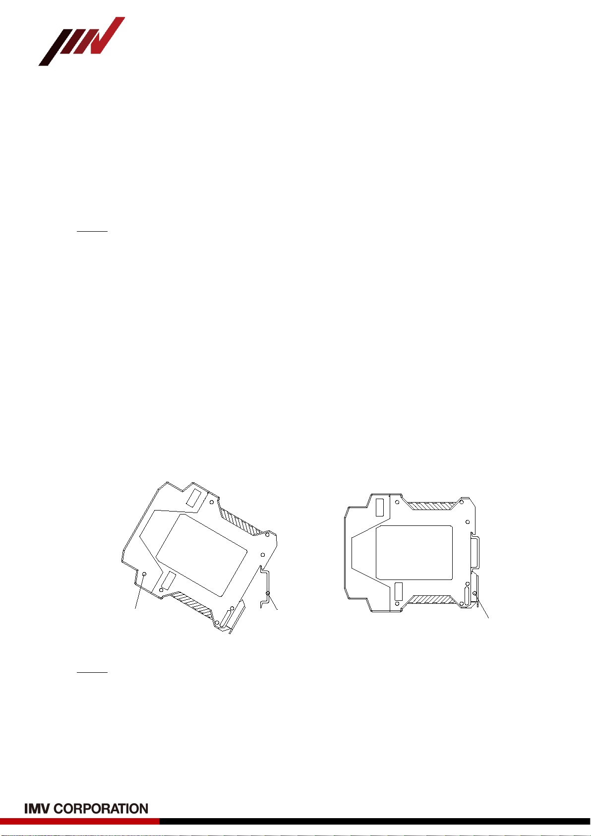
4-3. Installation of Converter
Converter is mounted using 35mm DIN rails (Fig.4-3).
(1) Hook the upper side of converter body on DIN.
(2) While pulling down stopper on the lower side of converter, hook it on the DIN rail.
Converter DIN Rail
Stopper
Fig.4-3 Installation of Converter
Memo
Install converter in a clean place with as little noise as possible and little vibration or
temperature change.
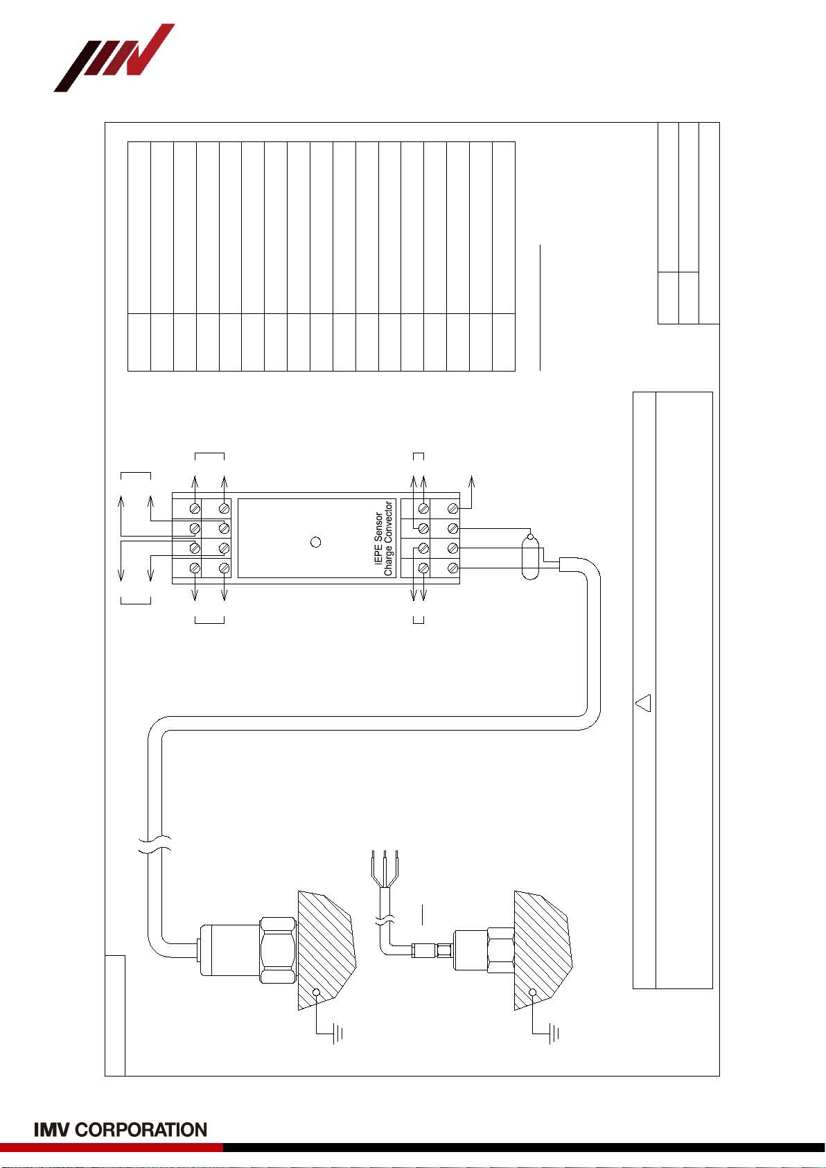
5. Wiring Method
Connect power supply, sensor and various subsequent instruments according to the
wiring diagram shown on the next page.
-8 -
VM-5011A Instruction Manuals
(TVE-6-4188E / Version 1.20)
図 番
Drawing No.
名 称
Drawing Name
VM-5011A Wiring Diagram
IMV CORPORATION
1
VM-5011A
TVE-6-4188E(1)
TVE-6-4188E(1)
234
5 6 78
16 15 14 13
12 11 10 9
POWER
White
Not normally
Use
Sensor
VP-100
-
E acceleration
DC Output
(1) The device to be measured to which sensor is attached must be grounded.
(2) In case of connecting VP-8021A, it is necessary to change the jumper pin settings inside VM-5011A.
Please refer to the "Appendix.1 How to connect with VP-8021A" for how to change it.
Number
1
How to Use
Sensro Input + (SIG)
Sensor Input - (COM)
Sensor Input (Shield Wire)
Not Normally Use (FG)
2
3
4
Sensor Waveform Output +
Sensor Waveform Output -
Power 24VDC +
Power 24VDC -
AC Output (Velocity) +
AC Output (E acceleration) +
DC Output (Velocity) +
DC Output (E acceleration) +
AC Output (Velocity) -
AC Output (E acceleration) -
DC Output (Velocity) -
DC Output (E acceleration) -
5
6
7
8
9
10
11
12
13
14
15
16
VM-5011A Use of each Terminal
+
-
Sensor
Waveform
Output
+
+
-
-
E acceleration
AC Output
Velocity
AC Output
Power
24VDC
Power Lamp Condition
OFF: Power is not supplied.
Sensor cable is broken.
O N: Normal (Measurement Status)
Caution
!
+
-
Velocity
DC Output
+
+
-
Black
Shield
Sensor
VP-8021A
Ground
Ground
IEPE + (Red)
IEPE - (White)
FG
VM-5011A
→ No.1
→ No.2
→ No.3
Note
The cable wire color is for standard
specifications, and custom specifications
cable are as specified separately.
-9 -
VM-5011A Instruction Manuals
(TVE-6-4188E / Version 1.20)
6. Power on Converter
After connecting according to "5. Wiring method", turn on the power and the "POWER"
lamp on the front of the converter will light up (Fig.6-1).
Memo
(1) This product takes about 30 seconds from power-on to stability.
(2) If "POWER" lamp is off even though power is being supplied, sensor cable may not
be connected properly, or sensor cable may be broken. In such a case, turn off
power supply to the converter once, check that sensor cable is connected correctly,
and then turn on power again.
VM-5011A
Power
IEPE Sensor
signal converter
Fig.6-1 POWER Lamp Indication
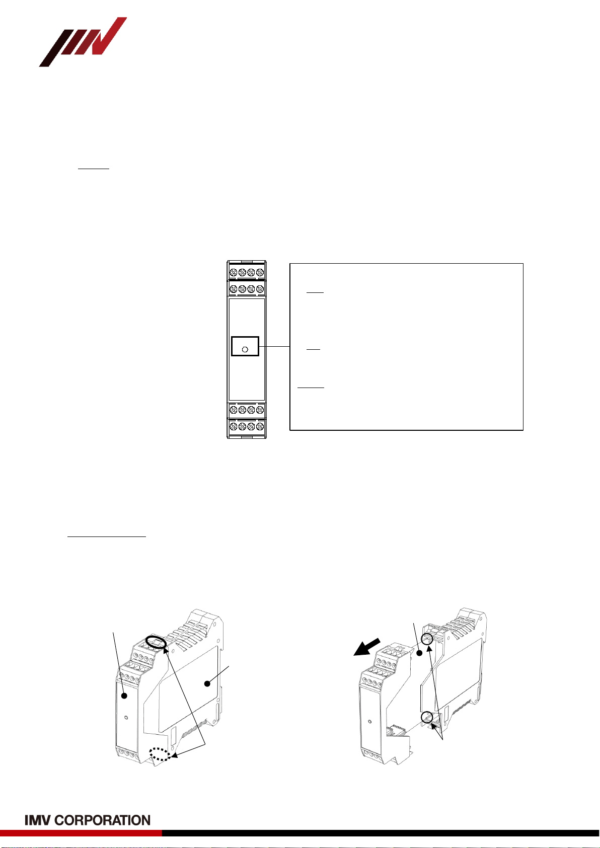
7. Change of Measurement Range and DC Output
Converter can change measurement range and DC output. Follow the procedure below.
Setting Method
(1) Turn off power supply to converter and disconnect all wiring connected to converter.
(2) Remove the transducer from the DIN rail.
(3) Push lock hooks on the top and bottom of converter with a flat-blade screwdriver, etc. to
release the lock, then hold upper housing and pull it out from base housing (see Fig.7-1).
Fig.7-1 Pulling out upper housing
Hold upper housing
and pull it out
When returning to original
position, align board with
guide (groove).
substrate
Unlock lock hook
using a flat-blade
screwdriver, etc.
Base Housing
Upper Housing
Status of POWER Lamp
OFF
(1) Power is not supplied
(2) Sensor is not connected
(3) Sensor cable is broken
ON
Normal (Measurement Status)
Memo
If sensor is not connected or sensor cable is
broken, output of 4-20mA will be about 2mA
(0V for 0-10V).

-10 -
VM-5011A Instruction Manuals
(TVE-6-4188E / Version 1.20)
(4) Change measurement range and DC output according to Fig.7-2 below.
“JP” and “SW” Setting Item
Setting
Factory Default
JP1 E acceleration
DC Output
1-2
4-20mADC
✔
2-3
0-10VDC
JP2 Velocity
DC Output
1-2
4-20mADC
✔
2-3
0-10VDC
SW1
(*)
E acceleration
Measuring Range
1
0~10m/s2E rms
2
0~25m/s2E rms
3
0~50m/s2E rms
✔
4
0~100m/s2E rms
SW2
(*)
Velocity
Measuring Range
1
10mm/s rms
2
25mm/s rms
3
50mm/s rms
✔
4
100mm/s rms
(*) Do not turn on more than one switch.
Fig.7-2 Setting of Measurement Range and DC Output
Note
(1) Do not change jumper or adjust variable resistance other than the above.
Correct measurement may not be possible.
(2) This product is a precision device. Please handle with care.
(3) Please do not forget to record and manage the settings.
(5) After completing the settings, insert upper housing into base housing, check that lock
hook is locked, attach it to the DIN rail, and reconnection each cable.
JP1
JP2
SW1
SW2
ON
Turn on the number of
the range to be set.
(this figure is No.3)
1
Enlarged View of SW1 and SW2
2
3
4
OFF
Jumper between 1-2 (4-20mA)
or 2-3 (0-10V).
Enlarged View of JP1 and JP2
3
2
1

-11 -
VM-5011A Instruction Manuals
(TVE-6-4188E / Version 1.20)
8. Handling precautions
Caution
(1) Avoid moving sensor during vibration measurement. When moving, turn off power
supply to converter before moving.
(2) Use a DC power supply for this product and use a stable power supply with little
external noise (noise surge pulse).
Note
When storing this product for a l
ong period of time, avoid places exposed to direct
sunlight, high humidity, and dusty places, and store it in a place within the operating
temperature and humidity range.
Memo
When disposing of this product, dispose of it as industrial waste.
9. Warranty
This product is shipped after the strict inspection in our factory. But in case the system
has the fault caused by the responsibility of IMV as the defect under production and
material during warranty period, we will repair or replace free of charge. However,
consumables such as lamps will be excluded.
In this case, it is limited to the warranty period. The warranty period of this product is
one year from the date of delivery. However, even within the warranty period, repairs will
be charged in the following cases.
(1) Any damage and breakdown caused by natural disaster such as fire, earthquake,
flood, lightning damage.
(2) Any transporting, moving, or dropping which does not related us after finishing our
delivery.
(3) Any error operation, unusual power supply input, and the fault caused by
disassembling/repairing/modifying by customer.

-12 -
VM-5011A Instruction Manuals
(TVE-6-4188E / Version 1.20)
10. Specifications
10-1. Specifications of Converter (VM-5011A)
Model
VM-5011A
Input Range
0~500m/s2
Measuring Range of
Frequency
E acceleration 10Hz to 1kHz
Band Pass Filter: 500Hz~10kHz
See “10-2. Standard Characteristic of Converter”
Velocity 10Hz to 1kHz
(ISO 2954:2012 Filter Characteristics compliant)
See “10-2. Standard Characteristic of Converter”
Measuring Range (*) E acceleration □10m/s
2
E rms
□25m/s2E rms
■50m/s2E rms
□100m/s
2
E rms
Velocity □10mm/s rms
□25mm/s rms
■50mm/s rms
□100mm/s rms
Connect Sensor (*) ■VP-100
□VP-8021A
DC Output (*) E acceleration ■4-20mA (Load 500Ωor lower)
□0-10V (Load 100kΩor higher)
Velocity ■4-20mA (Load 500Ωor lower)
□0-10V (Load 100kΩor higher)
AC Output
E acceleration
0-1Vrms (Load 100kΩor higher)
Velocity
0-1Vrms (Load 100kΩor higher)
Linearity
DC Output
within ±3%F.S
AC Output
within ±5%
Sensor Waveform Output Depends on Sensor Voltage Sensitivity
Bias Voltage: 9VDC
Operating Temperature
and Humidity Range
0 to 50℃、95%RH or less
without freezing or condensation
Suitable Cable of Terminal Block 0.2 to 2.5mm
2
(Single wire / Stranded wire)
(AWG12 to 24)
Power Supply of Converter
DC24V±10%
Power Supply of Sensor
DC24V 3.5mA±20%
Power Consumption
3W or less
Case Material
Resin
Outer Dimensions (Excluding protrusions)
W22.6×H99×D113.6mm (See p.13)
Weight
Approx. 150g
* ”■” is factory default settings.
-13 -
VM-5011A Instruction Manuals
(TVE-6-4188E / Version 1.20)
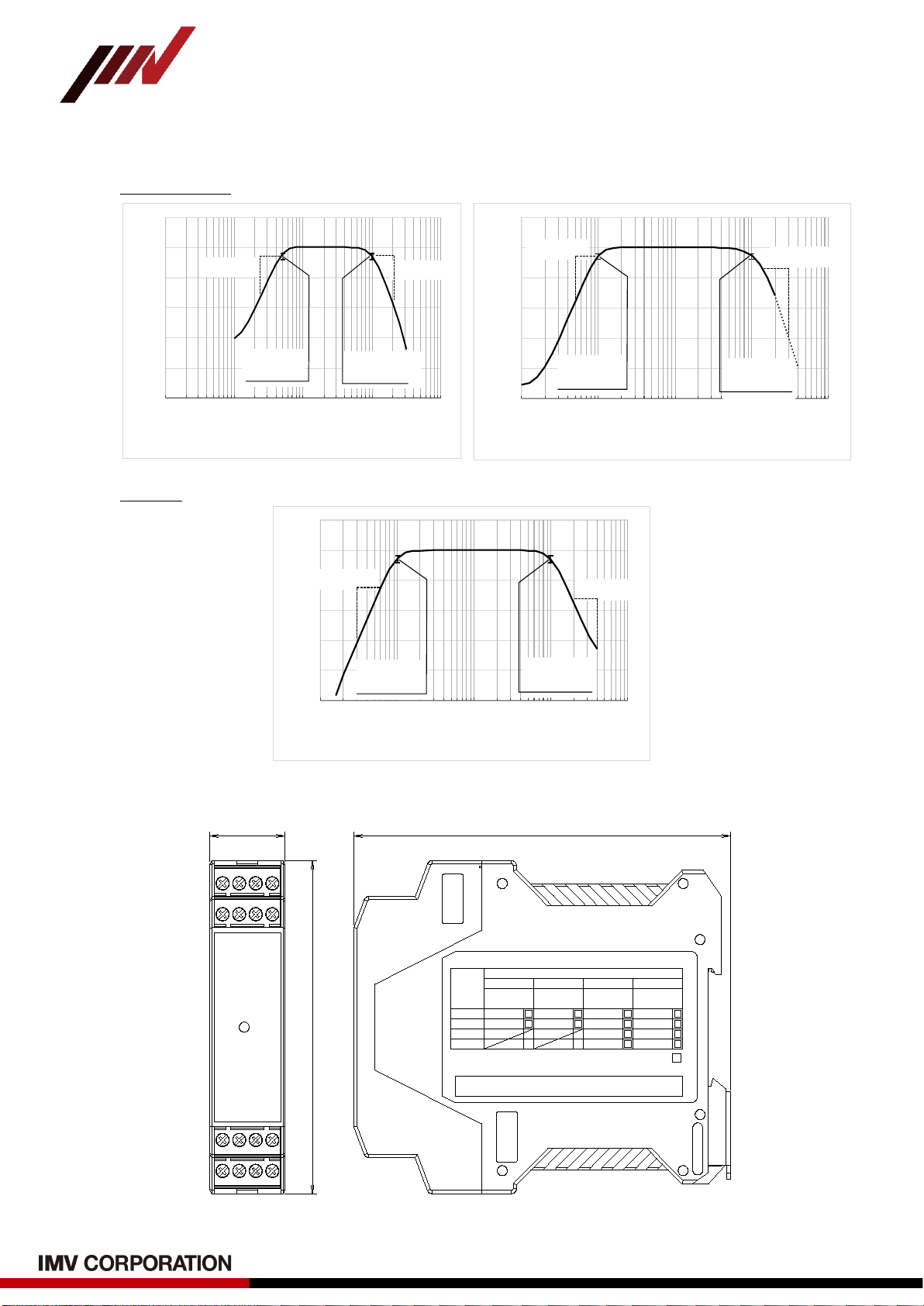
10-2. Standard Characteristic of Converter
E acceleration
Velocity
10-3. Outer dimensions of Converter
113.6
99
22.6
IEPE Sensor
Voltage
Input Type
0
1
2
3
1 2 3 4
Sensitivity Output1 Range Output2 Range
[ mV / m/s ]
2
[ m/s E ]
2
RMS
[ mm/s ]
RMS
Custom Code
Custom
Code No.
VM-5011A
IEPE Sensor signal converter
10.2
3.9
10
25
50
100
10
25
50
100
QC Pass :
VM-5011A
Power
IEPE Sensor
signal converter
Unit [mm]
-50
-40
-30
-20
-10
0
10
10 100 1000 10000 100000
Response[dB]
Frequency[Hz]
Env.Acc. First sta ge fi lter characteri stics
fc:10Hz
-3dB±1dB
fc:10000Hz
-3dB±1dB
-18dB/oct -18dB/oct
-50
-40
-30
-20
-10
0
10
110 100 1000 10000
Response[dB]
Frequency[Hz]
Env.Acc. Rea r s ta ge fi l ter cha r ac teri s tic s
fc:10Hz
-3dB±1dB
fc:1000Hz
-3dB±1dB
-18dB/oct -24dB/oct
-50
-40
-30
-20
-10
0
10
110 100 1000 10000
Response[dB]
Frequency[Hz]
Velocity filter characteristics
fc:10Hz
-3dB±1dB
fc:1000Hz
-3dB±1dB
-18dB/oct
-18dB/oct

-14 -
VM-5011A Instruction Manuals
(TVE-6-4188E / Version 1.20)
10-4. Specifications of Piezoelectric Acceleration Sensor
(1) VP-100 (Cable Direct Leading Type)
Detecting Method
Compression Type
Resonance Frequency
22kHz or more
Frequency Range
2Hz to 10kHz ±1dB
Voltage Sensitivity
10.2mV/(m/s
2
) ±10%
Max Measurement Acceleration
784m/s
2
Sensor Drive Current
0.5 to 8mA (18 to 30VDC)
Operating Temperature
-55 to +140℃
Protection Class
IP65
Weight
Approx. 125g (without Cable)
Case Material
SUS303
Mounting Method
M6 Screw
Cable Sheath Material
SUS Braided Cable
Cable Length
5m (Standard Length)
Outer Dimensions
See below Figure
456
M6(P=1) Male Screw
φ22
22
φ4
1/4-28"UNF - M6 Screw Mounting
Outer Dimensions of VP-100 (Unit: mm)

-15 -
VM-5011A Instruction Manuals
(TVE-6-4188E / Version 1.20)
(2) VP-8021A (including Cable with a Connector)
Detecting Method
Capacitance (MEMS) Type
Resonance Frequency
17kHz or more
Frequency Range
10Hz to 8kHz ±3dB
Voltage Sensitivity
3.9mV/(m/s
2
) ±5%
Max Measurement Acceleration
490m/s
2
Sensor Drive Current
3.5mA (Typ.) DC24V (Max.)
Operating Temperature
-30 to +120℃
Weight
Approx. 15g
Case Material
A5052 (Alumite treatment)
Mounting Method
M6 Screw
Cable Sheath Material
ETFE
Cable Length
5m (Standard Length)
Outer Dimensions
See below Figure
Outer Dimension of VP-8021A (Unit: mm)
M6(P=1)
Depth 5mm

-16 -
VM-5011A Instruction Manuals
(TVE-6-4188E / Version 1.20)
11. Maintenance and Troubleshooting
11-1. Maintenance
Check the following items when performing maintenance and inspection.
(1) Maintenance of Converter
(a) Is the screw at the connector terminal where cable is connected loose?
(b) Is the connected cable damaged?
(c) Is the power supply as specified (whether POWER lamp is on)?
(d) Is there any abnormal heat generation while the power is on?
(2) Maintenance of Sensor
(a) Is sensor installed loosely (is it securely installed)?
(b) Is sensor or sensor cable damaged?
(c) Is there a problem with the grounding of measurement target device to which
sensor is attached?
11-2. Troubleshooting
If you feel any malfunction or abnormality, please check the following before
requesting repair or replacement. If the problem persists even after checking the
following, please contact the purchasing agent or us.
Status
Cause
Treatment
POWER lamp does not
light.
Power is not being supplied.
Please supply power.
Cable connection is not made, or
cable connection is incorrect.
Make sure to connect them securely.
The supply power supply voltage is
out of the specification range.
Check the power supply
specifications.
Sensor does not connect.
Please connect sensor.
Sensor cable is disconnection.
Replace sensor cable.
Output of DC4-20mA does
not change from 2mA.
Sensor cable is unconnected or
disconnected.
Connect sensor cable correctly.
Vibration measurements
are very small (large).
Sensor is installed in the wrong
detection direction.
Reinstall in the correct detection
direction.
Vibration is small (large).
―
①Vibration measurements
are very unstable.
②Suddenly, vibration
measurement became
extremely large (small).
Sensor is not securely fixed.
Please fix it securely.
There is a poor contact in cable
connection part of converter.
Please connect it securely.
Sensor is out of order. If you own sensors with the same
specifications, replace sensors and
check if the phenomenon is
reproduced or replaced.
Converter is out of order. If you own converters with the same
specifications, replace converters and
check if the phenomenon is
reproduced or replaced.
Vibration is unstable or large (small).
―

-17 -
VM-5011A Instruction Manuals
(TVE-6-4188E / Version 1.20)
12. About Envelope Acceleration (E acceleration)
If the inner ring of a rolling bearing is scratched, vibration with an impact (several kHz or
more) will occur each time the rolling element passes through the scratch (Fig.12-1).
Fig.12-1 Example of impact waveform when bearing is abnormal
By processing the impact waveform by absolute value and passing it through a low-pass
filter, the envelope curve corresponding to the thick line in Fig.12-2 is obtained. By frequency
analysis of the obtained envelope, the repetition period (frequency) of impact can be obtained.
In addition, the waveform with impact also includes the primary rotation component and
low-frequency vibration component, and these components become noise in the envelope
processing, so they are removed in advance using a bandpass filter.
This product uses a bandpass filter of 500Hz to 10kHz before envelope processing, removes
primary rotation components and low frequency components, performs envelope processing,
and outputs the enveloped waveform as "E acceleration AC output". (See Figure 12-3).
Since the impact repetition frequency differs depending on which part of the bearing is
damaged, precise diagnosis is possible by frequency analysis using the E-acceleration AC
output.
In addition, the waveform after envelope processing is converted to 4-20mA or 0-10V
and output as a vibration level, so early detection of bearing abnormalities can be expected
by managing the vibration level.
Fig.12-3 Block Diagram of E acceleration
Repetition period
Fig.12-2 Envelope processing
Bandpass
Filter
500 to10kHz
Vibration
Waveform
Absolute
Value
Conversion
High Pass
Filter
10Hz
Low Pass
Filter
1kHz
Range
Setting
RMS-DC
Conversion
Buffer
4-20mA
Output
0-10V
Output
E Acc.
AC Output
E Acc.
DC Output
-18 -
VM-5011A Instruction Manuals
(TVE-6-4188E / Version 1.20)
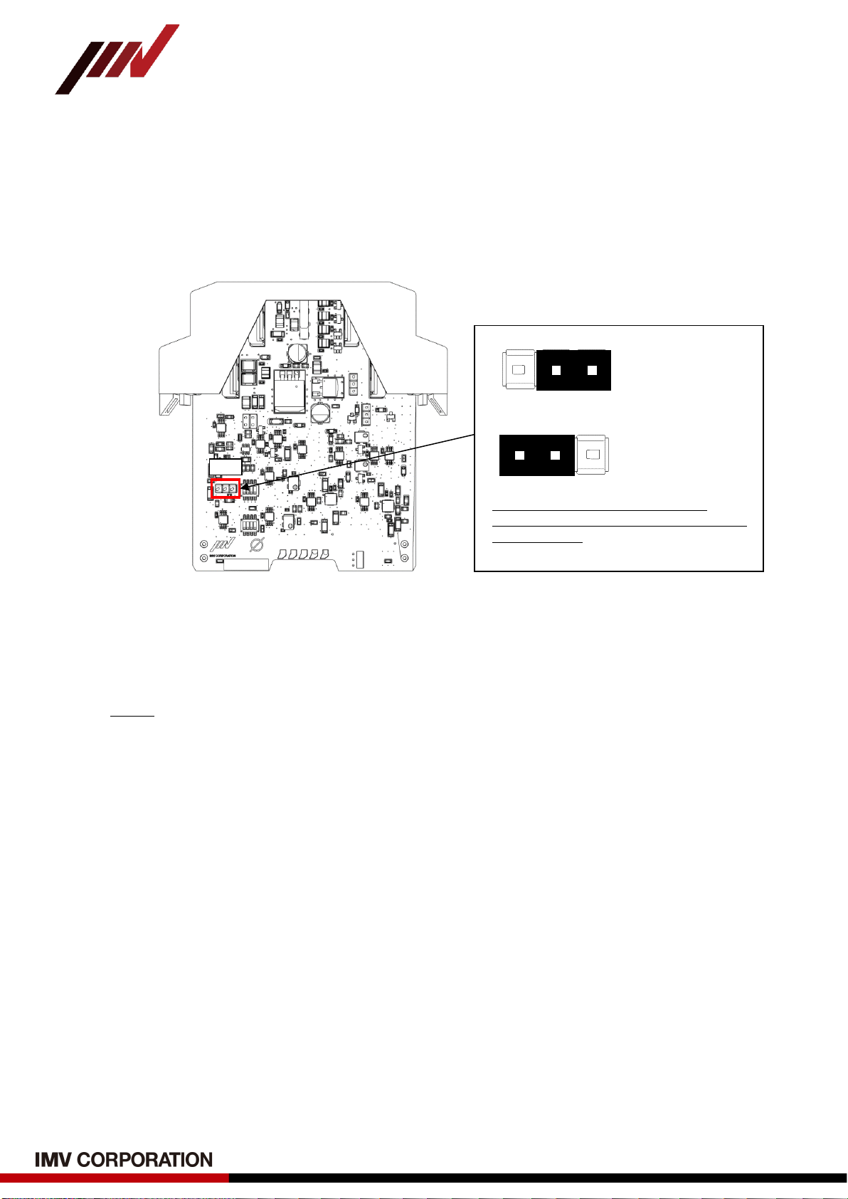
Appendix.1 How to connect with VP-8021A
Converter also supports connection with our MEMS high-frequency vibration sensor VP-
8021A.
Factory default connection sensor is set to VP-100. When connecting VP-8021A to
converter, it is necessary to change jumper JP4 settings on circuit board (see Fig.A-1).
Fig.A-1 Jumper change when connecting VP-8021A
Refer to "5. Wiring method" for how to connect the VP-8021A to the converter.
Memo
(1) Refer to "7. Change of Measurement Range and DC Output" for how to pull out the
board.
(2) For more information on VP-8021A, please check our website.
URL: https://www.imv.co.jp
JP4
3
2
1
Factory Default
(VP-100)
3
2
1
Settings when
connecting
VP-8021A
When connecting VP-8021A to
converter, change the jumper of JP4
between 2-3.
Enlarged View of JP4

-19 -
VM-5011A Instruction Manuals
(TVE-6-4188E / Version 1.20)
Appendix.2 When the place where sensor is attached is not grounded
Normally, the location where sensor is installed (the device to be measured) must be
grounded.
If for some reason sensor cannot be grounded, ground it via converter as shown in Fig.A-2.
1 2 34
5678
IEPE Sensor
signal convector
Sensor
Ground terminal 4
Fig.A-2 Wiring when sensor is not grounded
Memo
If the location where sensor is installed (device to be measured) is grounded,
do not make the above wiring.
By grounding at two points, a loop is formed through the ground wire, which
adversely affects the minute signal flowing through the sensor signal line, which may
prevent correct vibration measurement.

-20 -
VM-5011A Instruction Manuals
(TVE-6-4188E / Version 1.20)
Appendix.3 About voltage input connection specifications
The current for driving IEPE sensor (sensor) is output from sensor input terminal of
converter. This converter can be set to ON (IEPE sensor connection) or OFF (voltage input
connection) of the drive current supply with jumper JP3 (see Fig.A-3).
Fig.A-3 Sensor drive current supply setting
Memo
(1) Refer to "7. Change of Measurement Range and DC Output" for how to pull out the
board.
(2) In the case of voltage input connection, POWER lamp lights up after power is
supplied regardless of the cable connection status to the sensor input terminal.
JP3
Enlarged View of JP3
IEPE Sensor
Connection
Current Supply ON
(Factory Default)
1
2
1
2
Voltage Input
Connection
Current Supply OFF
Note
Jumper settings other than those shown
above are prohibited.
Table of contents
Popular Media Converter manuals by other brands


Matrix Electronic Technology
Matrix Electronic Technology mini-i Series user manual

Ascent Communication Technology
Ascent Communication Technology EC2200 user guide

Lindy
Lindy 32870 Installation and use

SIIG
SIIG CE-H22Z11-S1 User reference guide

aci
aci ACCESS series Installation & operation instructions

Apantac
Apantac DA-HDTV-SDI user manual


