IN-ECO CIWLI2001A User manual

说明书材质要求:105g铜版纸
折叠方式:骑马钉
说明书成品尺寸: 137x195mm
备注:
第二:特别注意:
1.印刷时看样请参考我司提供的实物样品颜色。不得偏色
2.137C的专色不得参考C=0,M=35,Y=90,K=0对应的四色
色谱颜色来看样印刷
第一:
专色用6级防晒油墨
+CMYK油墨要求:
1.PANTONE137C专色油墨(
专色用6级防晒油墨):
2.C色油墨:泗联天蓝墨
3.M色油墨:泗联金红墨
4.Y色油墨:pantone123C专色油墨
5.K色油墨:泗联黑墨
如果自己配色,油墨配比为:泗联中黄
(
防晒)
2000g
泗联金红
(
防晒)
225g
特别注意:此页内容不印刷
日期 设计师
更改记录
版本号
1.新设计
2021.10.30 蔡鑫宇1121.V01

Lithium-Ion Impact Wrench
Llave De Impacto De Iones De Litio
Visseuse À Choc Li-ion
Lithium-Ion Impact Wrench
Llave De Impacto De Iones De Litio
Visseuse À Choc Li-ion
EN
ES
FR
CIWLI2001A CIWLI2001AX CIWLI2001A-X
(X stands for 1 to 9)
INGCO Global
S
a
m
e
Ba
t
t
e
r
y
1
2
0
+
T
o
o
ls

The symbols in instruction manual and the label on the tool
Double insulated for additional protection.
Read the instruction manual before using.
CE conformity.
Wear safety glasses, hearing protection and dust mask.
Charging the battery only below 40ºc
Always recycle batteries
Do not destroy battery by fire
Do not expose battery to water
Waste electrical products should not be disposed of with household waste.
Please recycle where facilities exist. Check with your Local Authority or
retailer for recycling advice.
Safety alert.
Please only use the accessories supported by the manufacturer.
|English

3|English
GENERAL POWER TOOL SAFETY WARNINGS
WARNING Read all safety warnings and all instructions.Failure to
follow the warnings and instructions may result in electric shock, fire and/or
serious injury.
Save all warnings and instructions for future reference.
The term "power tool" in the warnings refers to your mains-operated (corded)
power tool or battery-operated (cordless) power tool.
1) Work area safety
a) Keep work area clean and well lit. Cluttered and dark areas invite
accidents.
b) Do not operate power tools in explosive atmospheres, such as
in the presence of flammable liquids, gases or dust. Power tools
create sparks which may ignite the dust or fumes.
c) Keep children and bystanders away while operating a power
tool. Distractions can cause you to lose control.
2) Electrical safety
a) Power tool plugs must match the outlet. Never modify the plug
in any way. Do not use any adapter plugs with earthed
(grounded) power tools. Unmodified plugs and matching outlets will
reduce risk of electric shock.
b) Avoid body contact with earthed or grounded surfaces such as
pipes, radiators, ranges and refrigerators. There is an increased
risk of electric shock if your body is earthed or grounded.
c) Do not expose power tools to rain or wet conditions. Water
entering a power tool will increase the risk of electric shock.
d) Do not abuse the cord. Never use the cord for carrying, pulling
or unplugging the power tool. Keep cord away from heat, oil,
sharp edges or moving parts. Damaged or entangled cords
increase the risk of electric shock.
e) When operating a power tool outdoors, use an extension cord
suitable for outdoor use. Use of a cord suitable for outdoor use
reduces the risk of electric shock.
f) If operating a power tools in a damp location is unavoidable, use
a residual current device (RCD) protected supply. Use of an RCD
reduces the risk of electric shock.

4|English
3) Personal safety.Do not let familiarity gained from frequent use of tools
allow you to become complacent and ignore tool safety principles. A
careless action can cause severe injury within a fraction of a second.
a) Stay alert, watch what you are doing and use common sense
when operating a power tool. Do not use a power tool while you
are tired or under the influence of drugs, alcohol or medication.
A moment of inattention while operating power tools may result in
serious personal injury.
b) Use personal protective equipment. Always wear eye protection.
Protective equipment such as dust mask, non-skid safety shoes,
hard hat, or hearing protection used for appropriate conditions will
reduce personal injuries.
c) Prevent unintentional starting. Ensure the switch is in the off-
position before connecting to power source and/or battery pack,
picking up or carrying the tool. Carrying power tools with your
finger on the switch or energizing power tools that have the switch on
invites accidents.
d) Remove any adjusting key or wrench before turning the power
tool on. A wrench or a key left attached to a rotating part of the
power tool may result in personal injury.
e) Do not overreach. Keep proper footing and balance at all times.
This enables better control of the power tool in unexpected
situations.
f) Dress properly. Do not wear loose clothing or jewellery. Keep
your hair, clothing and gloves away from moving parts. Loose
clothes, jewellery or long hair can be caught in moving parts.
g) If devices are provided for the connection of dust extraction and
collection facilities, ensure these are connected and properly
used. Use of dust collection can reduce dust-related hazards.
4) Power tool use and care Keep handles and grasping surfaces dry, clean
and free from oil and grease. Slippery handles and grasping surfaces do
not allow for safe handling and control of the tool in unexpected situations.
a) Do not force the power tool. Use the correct power tool for your
application. The correct power tool will do the job better and safer at
the rate for which it was designed.
b) Do not use the power tool if the switch does not turn it on and off.
Any power tool that cannot be controlled with the switch is dangerous
and must be repaired.
c) Disconnect the plug from the power source and/or the battery
pack from the power tool before making any adjustments,
changing accessories, or storing power tools. Such preventive
safety measures reduce the risk of starting the power tool accidentally.

5|English
d) Store idle power tools out of the reach of children and do not allow
persons unfamiliar with the power tool or these instructions to
operate the power tool. Power tools are dangerous in the hands of
untrained users.
e) Maintain power tools. Check for misalignment or binding of
moving parts, breakage of parts and any other condition that may
affect the power tools operation. If damaged, have the power tool
repaired before use. Many accidents are caused by poorly maintained
power tools.
f) Keep cutting tools sharp and clean. Properly maintained cutting tools
with sharp cutting edges are less likely to bind and are easier to control.
g) Use the power tool, accessories and tool bits etc. in accordance
with these instructions, taking into account the working
conditions and the work to be performed. Use of the power tool for
operations different from those intended could result in a hazardous
situation.
5) Battery tool use and care
a) Recharge only with the charger specified by the manufacturer. A
charger that is suitable for one type of BATTERY pack may create a risk
of fire when used with another BATTERY pack.
b) Use power tools only with specifically designated BATTERY packs.
Use of any other BATTERY packs may create a risk of injury and fire.
c) When BATTERY pack is not in use, keep it away from other metal
objects, like paper clips, coins, keys, nails, screws or other small
metal objects, that can make a connection from one terminal to
another. Shorting the BATTERY terminals together may cause burns
or a fire.
d) Under abusive conditions, liquid may be ejected from the BATTERY;
avoid contact. If contact accidentally occurs, flush with water. If liquid
contacts eyes, additionally seek medical help. Liquid ejected from the
BATTERY may cause irritation or burns.
e) Do not use a BATTERY pack or tool that is damaged or modified.
Damaged or modified batteries may exhibit unpredictable behaviour
resulting in fire, EXPLOSION or risk of injury.
f) Do not expose a BATTERY pack or tool to fire or excessive
temperature. Exposure to fire or temperature above 130 °C may cause
explosion.
g) Follow all charging instructions and do not charge the BATTERY
pack or tool outside the temperature range specified in the
instructions. Charging improperly or at temperaturesoutside the specified
range may damage the BATTERY and increase the risk of fire.

Cordless impact driver safety
warnings
1. Hold power tool b y insulated gripping sur-
faces, when performing an operation where
the fastener may contact hid d en wiring.
Fasteners contacting a " live" wire may mak e
exposed metal parts of the power tool " live" and
could give the operator an electric shock .
2. Be sure no one is b elow when using the tool in
high locations.
3.
4. W ear ear protectors.
5. D o not touch the b it or the workpiece immed i-
ately after operation. They may b e extremely
hot and could b urn your sk in.
6. K eep hand s away from rotating parts.
SAVE THESE INSTRUCTIONS.
WAR NING :
D O N O T let comfort or familiarity
with prod uct ( gained from repeated use) replace strict
ad herence to safety rules for the sub j ect prod uct.
MI SUSE or failure to follow the safety rules stated in this
instruction manual may cause serious personal inj ury.
Symbols
The followings show the symb ols used for tool.
volts
d irect current
no load speed
revolutions or reciprocation per minute
numb er of b low
Important safety instructions for
battery cartridge
1.
Before using b attery cartrid ge, read all instruc-
tions and cautionary mark ings on ( 1) b attery
charger, ( 2) b attery, and ( 3) prod uct using b attery.
2. D o not d isassemb le b attery cartrid ge.
3. I f operating time has b ecome excessively
shorter, stop operating immed iately. I t may
result in a risk of overheating, possib le b urns
and even an explosion.
|English
ENGLISH (Original instructions)
•without notice.
•
SPECIFICATIONS
Machine screw
Stand ard b olt
High tensile b olt
Hard impact mod e
Soft impact mod e
Hard impact mod e
Soft impact mod e
Rated voltage
Charging time
Fastening capacities
I mpacts per minute
N o load speed ( RPM)
Machine screw
Stand ard b olt
High tensile b olt
Hard impact mod e
Soft impact mod e
Hard impact mod e
Soft impact mod e
Rated voltage
Charging time
Fastening capacities
I mpacts per minute
N o load speed ( RPM)
1Hr approx
M10 - M20
M10 - M16
5 mm - 14 mm
0 - 2100 /min
0 - 1300 /min
0 - 2000 /min
Max.20V
0 - 3300 /min
6) Service
a) Have your power tool serviced by a qualified repair person using
only identical replacement parts. This will ensure that the safety of the
power tool is maintained.
b ) Never service damaged BATTERY packs. Service of BATTERY
packs should only be performed by the manufacturer or authorized s
ervice providers.

4 . If electrolyte gets into your eyes, rinse them
out with clear water and seek medical atten-
tion right away. It may result in loss of your
eyesight.
5 . Do not short the battery cartridge:
( 1)Do not touch the terminals with any con-
ductive material.
( 2)Avoid storing battery cartridge in a con-
tainer with other metal obj ects such as
nails, coins, etc.
( 3)Do not ex pose battery cartridge to water
or rain.
A battery short can cause a large current
breakdown.
6 . Do not store the tool and battery cartridge in
locations where the temperature may reach or
ex ceed 5 0 ° C ( 122 ° F) .
7 . Do not incinerate the battery cartridge even if
it is severely damaged or is completely worn
8 . Be careful not to drop or strike battery.
9 . Do not use a damaged battery.
10 . The contained lithium-ion batteries are subj ect
to the Dangerous G oods Legislation req uire-
ments.
F or commercial transports e.g. by third parties,
forwarding agents, special requirement on pack-
aging and labeling must be observed.
F or preparation of the item being shipped, consult-
ing an ex pert for hazardous material is required.
P lease also observe possibly more detailed
national regulations.
Tape or mask off open contacts and pack up the
battery in such a manner that it cannot move
around in the packaging.
11. Follow your local regulations relating to dis-
posal of battery.
SA V E TH ESE INSTRUCTIONS.
CAUTION:Only use genuineING C Obattteries.
U se of non-genuine batteries, or batteries that
have been altered, may result in the battery bursting
IN GC O
Tips for maintaining max imum
battery life
1. C harge the battery cartridge before completely
discharged. A lways stop tool operation and
charge the battery cartridge when you notice
less tool power.
2. Never recharge a fully charged battery car-
tridge. Overcharging shortens the battery
service life.
3.
1. B utton 2. B attery cartridge
To remove the battery cartridge, slide it from the tool
while sliding the button on the front of the cartridge.
To install the battery cartridge, align the tongue on the
battery cartridge with the groove in the housing and slip
it into place. Insert it all the way until it locks in place
with a little click.
and result in damage to the tool and battery cartridge
and a personal injury.
cartridge. F ailure to hold the tool and the battery
C harge the battery cartridge with room tem-
perature at 10 ° C - 4 0 ° C ( 5 0 ° F - 10 4 ° F) . Let
a hot battery cartridge cool down before
charging it.
4 . C harge the battery cartridge if you do not use
it for a long period ( more than six months) .
also void the I N GCO warranty for the I N GCO tool and
charger. CAUTION: $OZD\VLQVWDOOWKHEDWWHU\FDUWULGJH
IXOO\XQWLOWKHUHGLQGLFDWRUFDQQRWEHVHHQI f not,
it may accid entally fall out of the tool, causing inj ury to
you or someone around you.
CAUTION: 'RQRWLQVWDOOWKHEDWWHU\FDUWULGJH
IRUFLEO\ I f the cartrid ge d oes not slid e in easily, it is
not b eing inserted correctly.
CAUTION: $OZD\VVZLWFKRIIWKHWRROEHIRUH
LQVWDOOLQJRUUHPRYLQJRIWKHEDWWHU\FDUWULGJH
CAUTION: +ROGWKHWRRODQGWKHEDWWHU\FDU
)81&7,21$/
'(6&5,37,21
CAUTION: $OZD\VEHVXUHWKDWWKHWRROLV
VZLWFKHGRIIDQGWKHEDWWHU\FDUWULGJHLVUHPRYHG
EHIRUHDGMXVWLQJRUFKHFNLQJIXQFWLRQRQWKHWRRO
,QVWDOOLQJRUUHPRYLQJEDWWHU\
FDUWULGJH
_(QJOLVK
2
1

Indicating the remaining battery
capacity
►1. Indicator lamps 2. C heck button
P ress the check button on the battery cartridge to indi-
cate the remaining battery capacity. The indicator lamps
light up for few seconds.
NOTE: D epending on the conditions of use and the
ambient temperature, the indication may differ slightly
from the actual capacity.
> 8 0 %
30 % to 8 0 %
< 30 %
Indicator lamps Remaining
capacity
Lighted Off
Tool / battery protection system
The tool is equipped with a tool/battery protection sys-
tem. This system automatically cuts off power to the
motor to ext end tool and battery life. The tool will auto-
matically stop during operation if the tool or battery is
placed under one of the following conditions:
Overload protection
W hen the battery is operated in a manner that causes
it to draw an abnormally high current, the tool automat-
ically stops without any indication. In this situation, turn
the tool off and stop the application that caused the tool
to become overloaded. Then turn the tool on to restart.
Overheat protection
W hen the tool/battery is overheated, the tool stops
automatically. In this situation, let the tool/battery cool
before turning the tool on again.
Switch action
CAUTION: Before installing the battery car-
tridge into the tool, always check to see that the
switch trigger actuates properly and returns to
the "OFF" position when released.
To start the tool, simply pull the switch trigger. Tool
speed is increased by increasing pressure on the switch
trigger. R elease the switch trigger to stop.
NOTE: The tool automatically stops if you keep pull-
ing the switch trigger for about 6 minutes.
Electric brake
This tool is equipped with an electric brake. If the tool
consistently fails to quickly stop after the switch trigger
is released, have the tool serviced at a IN GC O service
center.
Lighting up the front lamp
CAUTION:Do not look in the light or see the
source of light directly.
1
►1. L amp
_(QJOLVK
1
►1. Switch trigger
1
1
2
2

1. R eversing switch lever
CAUTION: A lways check the direction of
rotation before operation.
CAUTION: U se the reversing switch only after
the tool comes to a complete stop.C hanging the
direction of rotation before the tool stops may dam-
age the tool.
CAUTION: W hen not operating the tool,
always set the reversing switch lever to the neu-
tral position.
This tool has a reversing switch to change the direction
of rotation. D epress the reversing switch lever from the
A side for clockwise rotation or from the B side for coun-
terclockwise rotation.
W hen the reversing switch lever is in the neutral posi-
tion, the switch trigger cannot be pulled.
1. Hard 2. Soft 3 . B utton
Y ou can change the impact force in three steps: hard,
soft.
This allows a tightening suitable to the work.
E very time the button is pressed, the number of blows
changes in two steps.
C hanging the impact force
1
23
H igh
Low
Change
only when
running !
Only Clockwise !
H igh
Low
Change
only when
running !
Only Clockwise !
Reversing switch action
►1. B utton
H igh
Low
Change
only when
running !
Only Clockwise !
1
,PSDFWIRUFHJUDGHGLVSOD\HG
RQSDQHO
0D[LPXPEORZV 3XUSRVH ([DPSOHRIDSSOLFDWLRQ
High 3, 300 min- 1 ( /min) Tightening when force and
speed are d esired . Tightening wood screws,
tightening b olts.
Low 2, 000 min- 1 ( /min) Tightening with less force to
avoid screw thread b reak age. Tightening sash screws, tight-
ening small screws such as M6.
127( Amod e is availab le only when the tool rotates clock wise. W hen rotating counterclock wise in A mod e, the
impact force and speed are the same as hard mod e.
127( W hen all lamps on the switch panel go out, the tool is turned off to save the b attery power. The impact force
grad e can b e check ed b y pulling the switch trigger to the extent that the tool d oes not operate.
127( W hile pulling the switch trigger, the impact force grad e cannot b e changed .
+LJK
/RZ
Change
only when
running !
Only Clockwise !
+LJK
/RZ
Change
only when
running !
Only Clockwise !
High
Low
+LJK
/RZ
Change
only when
running !
Only Clockwise !
+LJK
/RZ
Change
only when
running !
Only Clockwise !
,PSDFWIRUFHJUDGHGLVSOD\HG
RQSDQHO
0D[LPXPEORZV $SSOLFDWLRQ :RUN
3, 300 min
2, 000 min
- 1 ( /min) Tightening when force and
speed are d esired . Assemb ling the steel frame.
ad j ustment with small d iameter
b olt.
Assemb ling furnitures.
+LJK
/RZ
Change
only when
running !
Only Clockwise !
_(QJOLVK
Change
only when
running !
Change
only when
running !
B
A
1

A SSEM BLY
CAUTION: A lways be sure that the tool is
switched off and the battery cartridge is removed
before carrying out any work on the tool.
Selecting correct impact socket
Always use the correct size impact socket for bolts and
nuts. An incorrect size impact socket will result in inac-
curate and inconsistent fastening torque and/or damage
to the bolt or nut.
Installing or removing impact socket
CAUTION: M ake sure that the impact socket
and the mounting portion are not damaged before
installing the impact socket.
CAUTION: A fter inserting the impact socket,
do not use it.
►1. Impact socket 2. Square drive
Align the hole in the side of the impact socket with the
detent pin on the square drive and push the impact
socket onto the square drive until it locks into place. Tap
it lightly if required.
To remove the impact socket, simply pull it off.
Installing hook
►1. Groove 2. Hook 3 . Screw
The hook is convenient for temporarily hanging the tool.
This can be installed on either side of the tool. To install
the hook, insert it into a groove in the tool housing on
either side and then secure it with a screw. To remove,
loosen the screw and then take it out.
OP ERA TION
CAUTION:
A lways insert the battery cartridge
all the way until it locks in place. If you can see the
red indicator on the upper side of the button, it is not
locked completely. Insert it fully until the red indicator
cannot be seen. If not, it may accidentally fall out of the
tool, causing injury to you or someone around you.
the bolt or nut. Turn the tool on and fasten for the proper
fastening time.
1
2
_(QJOLVK
3
2
1
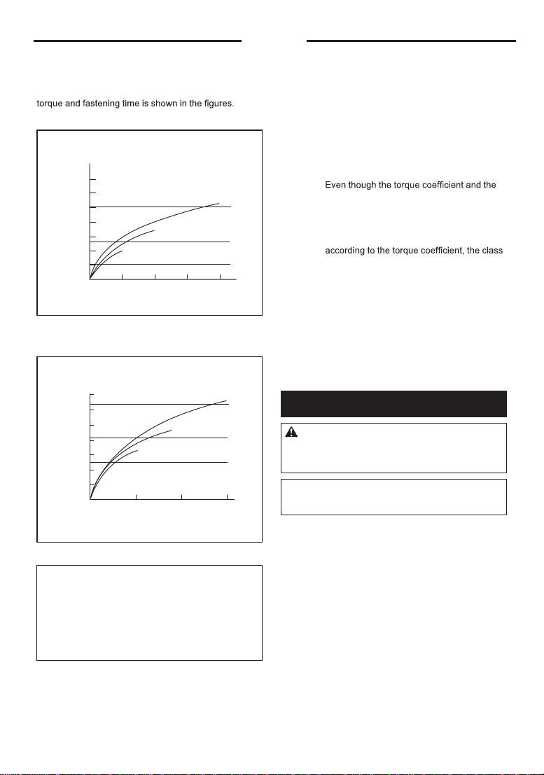
The proper fastening torq ue may d iffer d epend ing upon
the k ind or siz e of the b olt, the material of the work piece
to b e fastened , etc. The relation b etween fastening
3URSHUIDVWHQLQJWRUTXHIRUVWDQGDUGEROW
0
280
( 207)
12
M20
M16
M16
M20
M12 M12
N • m
( ft• lb s)
240
( 177)
200
( 148)
160
( 118)
120
( 89)
80
( 59)
40
( 30)
Fastening time ( second ) Fastening torq ue
3URSHUIDVWHQLQJWRUTXHIRUKLJKWHQVLOHEROW
0123
M12H
M14H
M16H
M12H
M14H
M16H
280
( 207)
240
( 177)
200
( 148)
160
( 118)
120
( 30)
80
( 59)
40
( 89)
N • m
( ft• lb s)
Fastening time ( second ) Fastening torq ue
127( Hold the tool pointed straight at the b olt or nut.
127( E xcessive fastening torq ue may d amage the
b olt/nut or impact sock et. Before starting your j ob ,
always perform a test operation to d etermine the
proper fastening time for your b olt or nut.
127(
I f the tool is operated continuously until the b attery
cartrid ge has d ischarged , allow the tool to rest for 15 min-
utes b efore proceed ing with a fresh b attery cartrid ge.
The fastening torq ue is affected b y a wid e variety of
factors includ ing the following. After fastening, always
check the torq ue with a torq ue wrench.
end ) will cause a red uction in the fastening torq ue.
3. Bolt
•class of b olt are the same, the proper fasten-
ing torq ue will d iffer accord ing to the d iame-
ter of b olt.
• E ven though the d iameters of b olts are the
same, the proper fastening torq ue will d iffer
of b olt and the b olt length.
4. The use of the universal joint or the extension
b ar somewhat red uces the fastening force of the
impact wrench. Compensate b y fastening for a
longer period of time.
5. The manner of hold ing the tool or the material
of d riving position to b e fastened will affect the
torq ue.
6. O perating the tool at low speed will cause a red uc-
tion in the fastening torq ue.
0$,17(1$1&(
CAUTION: $OZD\VEHVXUHWKDWWKHWRROLV
VZLWFKHGRIIDQGWKHEDWWHU\FDUWULGJHLVUHPRYHG
EHIRUHDWWHPSWLQJWRSHUIRUPLQVSHFWLRQRU
PDLQWHQDQFH
NOTICE: 1HYHUXVHJDVROLQHEHQ]LQHWKLQQHU
DOFRKRORUWKHOLNH'LVFRORUDWLRQGHIRUPDWLRQRU
FUDFNVPD\UHVXOW
To maintain prod uct SAFE TY and RE LI ABI LI TY ,
repairs, any other maintenance or ad j ustment should
b e performed b y I N GCO Authoriz ed or Factory Service
Centers, always using I N GCO replacement parts.
1. W hen the b attery cartrid ge is d ischarged almost
completely, voltage will d rop and the fastening
torq ue will b e red uced .
2. I mpact sock et
• Failure to use the correct siz e impact sock et
will cause a red uction in the fastening torq ue.
•
Aworn impact sock et ( wear on the hex end or sq uare
_(QJOLVK

|English
CIWLI2001A CIWLI2001AX CIWLI2001A-X (X stands for 1 to 9)
EXPLODED VIEW

1 |English
CIWLI2001A CIWLI2001AX CIWLI2001A-X (X stands for 1 to 9)
SPARE PART LIST
No. Part Description Qty
1
2
3
4
5
6
7
No. Part Description Qty
9
8
12
13
14
10
11
1
1
1
1
9
1
1
Tapping Screw ST3.9*22
Gear Box Assy & Hammer Assy
Stator
Motor Gear
Rotor
F/R Change Lever
Left&Right Shell
Function Panel
Terminal
Controller
Trigger
Tapping Screw ST3.5*16
Battery
Charger
4
1
1
1
1
1
1

CIWLI2001A CIWLI2001AX CIWLI2001A-X(X stands for 1 to 9)
www.ingco.com
MADE IN CHINA
1121.V01 No. 45 Songbei Road, Suzhou
Industrial Park, China.
INGCO TOOLS CO., LIMITED
This manual suits for next models
1
Table of contents
Popular Impact Driver manuals by other brands


Milwaukee
Milwaukee 9070-20 Operator's manual

Panasonic
Panasonic EY7202 - 12V IMPACT DRIVER operating instructions

Red Stone
Red Stone RS 10.8Li CC Original instructions

Pattfield Ergo Tools
Pattfield Ergo Tools PE-20 IDB Original instructions

RIDGID
RIDGID OCTANE R86039VN Operator's manual

Alemlube
Alemlube 6III4 owner's manual


