IN-ECO LR 060-H06 User manual
www.in-eco.eu
Air and Vacuum
Components
Operating Instructions
Liquid ring vacuum pumps
LR 060-H06, LR 061-H16


03
Contents
IN-ECO spol. s r.o.
Contents
1 Safety 06
1.1 Denitions 06
1.2 Safety alert symbol 06
2 Intended Use 08
3 Intended Use 08
4 Technical Data 09
4.1 Mechanical data 09
4.2 Operating conditions 10
5 Description of Vacuum Pump/Compressor 12
5.1 Design and principle 12
5.2 Operating method 12
5.3 Operating modes 13
5.3.1 Self-priming operation 13
5.3.2 Operation with operating-liquid feed 13
6 Transport and Handling 14
7 Installation 15
7.1 Installation 15
7.2 Electrical connection (motor) 16
7.3 Connecting pipes/hoses (vacuum pump/compressor) 17
7.3.1 Inlet connection 18
7.3.2 Discharge connection 18
7.3.3 Operating-liquid port 18
8 Commissioning 19
8.1 Preparation and start-up 19
8.2 Self-priming operation 20
8.3 Operation with operating-liquid feed 21
9 Operation 23
9.1 Self-priming operation 23
10 Shut-Down and Longer Standstills 24
10.1 Draining 24
10.2 Preparing for longer standstill 24
10.3 Storage conditions 25

04
Contents
IN-ECO spol. s r.o.
11 Servicing 25
11.1 Maintenance 26
11.2 Repairs/troubleshooting 28
11.3 Spare parts 30
11.3.1 Ordering IN-ECO spare parts 30
11.3.2 Ordering standardized parts 30
11.4 Service/Aer-sales service 30
11.5 Decontamination and Declaration of Clearance 30
12 Disposal 30
13 Accessories 31
13.1 Flanges 31
13.2 Non-return valve 31
13.3 Gas ejector 32
13.4 Liquid separator 33
13.5 Cavitation protection 34
14 Exploded View with Parts List 36
14.1 Parts list 36
14.2 Exploded view 37
15 Limited standard warranty 39
16 Waste disposal 39

05
06
1 Safety
1.1 Denitions
To point out dangers and important information, the following signal words and symbols
are used in these operating instructions:
1.2 Safety alert symbol
The safety alert symbol is located in the safety precautions in the highlighted heading eld on the left next to the signal
word (DANGER, WARNING, CAUTION). Safety precautions with a safety alert symbol indicate a danger of injuries.
Be sure to follow these safety precautions to protect against injuries or death! Safety precautions without a
safety alert symbol indicate a danger of damage.
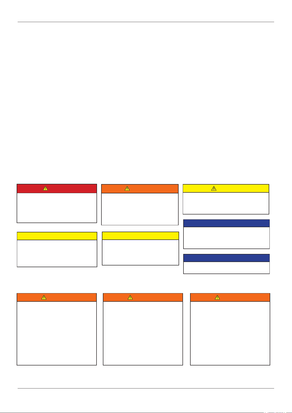
1.3 Signal words
1.4 Všeobecné bezpečnostné pokyny
DANGER
WARNING
CAUTION
NOTICE
NOTE
The signal words are located in the safety precautions in the highlighted heading
eld. They follow a certain hierarchy and indicate (in conjunction with the safe-
ty alert symbol, see Chapter 1.2) the seriousness of the danger and the type of
warning.
See the following explanations:
Safety
IN-ECO spol. s r.o.
DANGER
Danger of injuries.
Indicates an imminently hazardous situati-
on, that will result in death or
serious injury if the corresponding
measures are not taken.
WARNING
Danger of injuries.
Indicates a potentially hazardous
situation, that could result in death or
serious injury if the corresponding
measuresare not taken.
WARNING
Improper use of the unit can result in
serious or even fatal injuries!
These operating instructions:
> must have been read completely and
understood before beginning any work
with or at the pump-motor unit,
> must be strictly observed,
> must be available at the operating locati-
on of the pump-motor unit.
WARNING
Improper use of the unit can result in
serious or even fatal injuries!
Only operate the pump-motor unit
> for the purposes indicated under „Inten-
ded Use“! page 6!
> with the uids indicated under‚Intended
Use‘! page 6!
> with the values indicated under
‚Technical Data‘!, page 8!
WARNING
Improper use of the unit can result in
serious or even fatal injuries!
Transport and handling as well as assem-
bly and disassembly of the unit may be
carried out by trained and responsible
personnel only!
CAUTION
Danger of injuries.
Indicates a potentially hazardous situation,
that may result in minor or moderate injury
if the corresponding measures are not taken.
CAUTION
Danger of damage.
Indicates a potentially hazardous situation
that may result in property damage
if the corresponding measures are not
taken.
CAUTION
Danger of damage.
Indicates a potentially hazardous
situation that may result in property
damage if the corresponding measures
are not taken.
NOTICE
Indicates a possible disadvantage, i.e.
undesirable conditions or consequences can
occur if the corresponding measures are not
taken.
NOTE
Indicates a possible advantage if the corre-
sponding measures are taken; tip.

07
Safety
IN-ECO spol. s r.o.
DANGER
Electrical danger!
Before beginning work on the unit or system,
the following measures must be carried out:
> Deenergize.
> Secure against being switched on again.
> Determine whether deenergized.
> Ground and short-circuit.
> Cover or block off adjacent energized
parts.
DANGER
Electrical danger!
Work on electrical installations
may be carried out by trained
and authorized electricians only!
WARNING
When working on the unit, there is a
danger of injury,e.g. in the form of cuts/
cutting off, crushing and burns!
During transport/handling as well as assem-
bly and disassembly always wear personal
protective equipment (safety helmet, pro-
tective gloves, safety boots)!
WARNING
Hair and clothing can be pulled into the
unit or caught and wound up moving
parts!
Do not wear long, loose hair or
wide, loose clothes!
Use a hair net!
WARNING
Danger from rotating external fan of unit!
Only operate the unit with the fan
guard mounted!
WARNING
Danger from rotating external fan of unit!
Only operate the unit with the fan guard mounted!
It is prohibited to remove the fan guard!
WARNING
Danger due to gauge pressure and vacuum!
Danger due to escaping uid!
Danger from rotating external fan of unit!
Only operate the unit with the pipes/hoses connected to the
intake and discharge connection, as well as to the operating-
-liquid port!
WARNING
Danger in the form of cuts or cutting off extremities on
the impeller of the pump-motor unit!
> Do not reach into the unit through open connections!
> Do not insert objects into the unit through the openings!
WARNING
Danger due to gauge pressure and vacuum!
> Check the connections of the pipe/hose connections for
leaks!
WARNING
Danger due to gauge pressure and vacuum! Danger due
to escaping uid! Check the connections of the pipe/hose
connections for leaks!
WARNING
Danger of burns and scalding from hot surfaces of the
pumpmotor unit and from hot uids!
> Do not touch during operation!
> Allow to cool after shut-down!
WARNING
Danger in the form of cuts or cutting off extremities on
the impeller of the pump-motor unit!
> Do not reach into the unit through open connections!
> Do not insert objects into the unit
through the openings!
WARNING
Hazard: Long, loose hair can be drawn
into external fan through fan guard grate,
even with fan guard mounted!
Protective measures:
Wear hair net!
WARNING
Danger zone: Hot surface.
Hazard:
Burns/scalding possible.
Protective measures:
Do not touch! Wear protective gloves!
CAUTION
Danger of unit tipping over!
> Secure the pump-motor unit on the instal-
lation surface before putting into operation!
WARNING
Danger due to gauge pressure
and vacuum! Danger due to escaping
uid!
> Before beginning work on the unit or
system:
Interrupt supply of operating liquid.
> Bleed lines and vacuum pump/compressor
(depressurize).

08
2 Intended Use
These operating instructions
> apply to liquid-ring vacuum pumps/compressors of the LR series, types LR 060, LR 061
> contains instructions bearing on transport and handling, installation, commissioning, operation, shut-down, storage,
servicing and disposal of the LR
> must be completely read and understood by all operating and servicing personnel before beginning to work with or
on the LR,
> must be strictly observed,
> must be available at the site of operation of the LR.
About the operating and servicing personnel of the LR:
> These persons must be trained and authorized for the work to be carried out.
> Work on electrical installations may be carried out by trained and authorized electricians only.
3 Intended Use
The LR
> are pump-motor units for generating vacuum or gauge pressure
> are used to extract, transport and compress the following
> all dry and humid gases, which are not explosive or ammable
> preferably air or air/vapor mixtures
In case of corrosive or toxic gases/vapors contact service.
> are designed for operation with the following operating liquids:
– Water with a pH of 6 to 9, free of solid materials (such as sand)., If the pH values or operating liquids
differ, it is necessary to contact service.
> are intended for industrial applications, are designed for continuous operation.
When operating the LR the limits listed in Chapter 4, „Technical Data“, Pg. 9 ff. must
always be complied with.
Foreseeable Misuse
It is prohibited
> to use the LR in applications other than industrial applications unless the necessary protection is provided
on the system, e.g. guards suitable for children‘s ngers,
> to use the device in rooms in which explosive gases can occur if the LR is not expressly intended for this purpose;
> to extract, to deliver and to compress explosive, ammable, corrosive or toxic uids unless the L-BV7 is specically
designed for this purpose,
> to operate the LR with values other than those specied in Chapter 4, „Technical Data“, Pg. 9 ff.
Any unauthorized modications of the LR06 are prohibited for safety reasons. Any maintenance and repair work, such
as replacing worn or defective components, may only be carried out by companies authorized by the manufacturer
(please contact service).
Intended Use
IN-ECO spol. s r.o.

09
4 Technical Data
4.1 Mechanical data
Technical Data
IN-ECO spol. s r.o.
Dimensions
LR 060-H06 / LR 061-H16
Spare part list LR 060 - H06 / LR 0161 - H16
9.7
A2
A1
10.54
90
218
62.7 100
125
144.5
G1
171
139.5
165
13.5
G1/4
G1/4
G1/2
73.5
G1/4
G1/4
Typ A1 A2
LR 060-H16 368,4 287,9
LR 061-H06 386,7 287,9
1) Casing
2) Port plate
3) Impeller
4) Lantern
5) Motor
6) Mechanical seal
The recommended replacement
interval of the mechanical seal is
every 30 months.
Stainless steel
Stainless steel
Bronze
Cast iron with teon coating
IE1 motor
Pot lead
Material:
10
Minimum distances for heat dissipation
Max. discharge pressure p2 max during
compressor operation (at inlet pressure p1 =
1 bar abs. [14.5 psia]):
Temperatures Pressures
Technical Data
IN-ECO spol. s r.o.
4.2 Operating conditions
Type Minimum distance from
fan guard to adjacent surface
(mm) (inches])
LR 060-H16 34 1,34
LR 061-H06 34 1,34
Type
p2 max
[bar abs.] [psia]
at 50 Hz: at 60 Hz: at 50 Hz: at 60 Hz:
LR 060-H16 2 2 29,0 29,0
LR 061-H06 2 2 29,0 29,0
Temperature
of pumped
gases/va-
pors:
max. +80 °C [max. +176 °F]
At higher uid temperatures,
measures must be taken on
the system to prevent burns,
e.g. mount separating safety
device (cover).
Operating
liquid tem-
perature:
max. +80 °C [max. +176 °F] min.
+5 °C [min. +41 °F]
Nominal value:
+15 °C +59 °F]
Ambient
temperature:
max. +40 °C [+104 °F]
min. +5 °C [+41 °F]
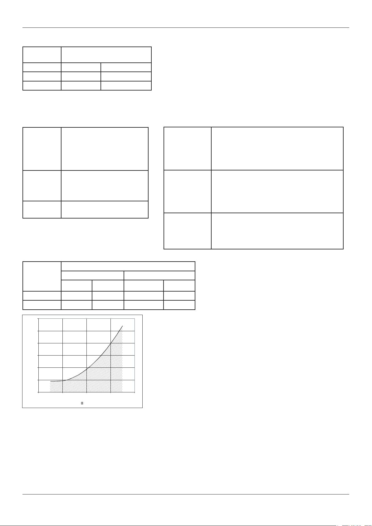
Min. inlet
pressure:
Dependent on the operating liquid temperature
(see Fig. 2, Pg. 10)
When this temperature is dropped below, the hose
ofthe liquid separator (accessory) must be connec-
ted to the connection for cavitation protection (Pg.
17).
Max.
discharge
pressure
during
vacuum-pump
operation:
1,1 bar abs. [16,0 psia]
Max.
permissible
pressure in
pump-motor
unit:
8 bar abs. [116 psia]
If higher pressures can occur in the system, then
corresponding protective devices must be provi-
ded.
Obr. 2: Minimum inlet pressure/cavitation limit
.[ °C, °F] = Temperature of operating liquid
p1 [mbar abs., psia] = Inlet pressure abs.
The minimum permissible inlet pressure of the pump-motor unit is dependent on the temperature of the operating
liquid. During operation without cavitation protection, the minimum inlet pressure must be set above the shaded area.
0
50
100
150
200
250
300
02 04 06 08 0
fl
[°C]
p
1
[mbara bs .]

11
Nominal operating-liquid ow rate
(with dry air extraction and with water at 15°C [59 °F] as operating liquid)
Operating-liquid lling amount for priming
Water requirement (L/min) / Inlet pressure P
Technical Data
IN-ECO spol. s r.o.
Type
Flow rate
[m³/h] [ft³/h]
at 50 Hz: at 60 Hz: at 50 Hz: at 60 Hz:
LR 060-H16 0,20 0,20 7,06 7,06
LR 061-H06 0,23 0,23 8,12 8,12
Type
Filling amount
[l] [gal (US)] [gal (UK)]
LR 060-H16 0,40 0,106 0,088
LR 061-H06 0,55 0,145 0,121
water Requirement
(L/min)
water Requirement
(L/min)
Inlet pressure P1(mbar abs.) Inlet pressure P1(mbar abs.)
0 100 200 300 400 500 600 700 800 900 1000
0
2.0
4.0
6.0
8.0
0 100 200 300 400 500 600 700 800 900 1000
0
0.4
0.6
0.8
1.0
LR 060-H06
LR 060-H06
LR 061-H16
LR 061-H16
8.0
6.0
4.0
2.0
50 Hz / RPM 2850/min 60 Hz / RPM 3450/min

12
5 Description of Vacuum Pump/Compressor
Description of Vacuum Pump/Compressor
IN-ECO spol. s r.o.
5.1 Design and principle
5.2 Operating method
When the impeller turns, the operating liquid is put into motion and accelerated. This forms a liquid ring that also rota-
tes. Due to centrifugal force, this ring is arranged concentrically to the housing and eccentrically to the impeller.
During a complete rotation of the impeller, the following occurs:
> The impeller cells are completely lled with operating liquid at the upper vertex.
> During the rst half rotation, the liquid ring lifts off the impeller hub. The space in the cells increases so that the pum-
ped gases/vapors are sucked in through the inlet port.
> The space in the cells is largest at the lower vertex, as these are virtually free of operating liquid.
> During the second half rotation, the liquid ring approaches the hub again. The space
in the cells decreases so that the pumped gases/vapors are compressed and pushed out through the discharge port
Fig. 3:
1
3
2
4
Rotor with xed blades (1) is rotating in the stator (2), in which is situated eccentrically. Water ring is created from
the service liquid (3) by the centrifugal force. The vacuum is formed and the pressure is changed in the compression
chambers (4) between the blades and water ring. During the operation, the pump has to be supplied by adequate
quantity of service liquid to achieve desired performance. Service liquid is also very useful for cooling of the liquid ring
vacuum pump and for receiving possible contamination of sucked gas.

13
Description of Vacuum Pump/Compressor
IN-ECO spol. s r.o.
5.3 Operating modes
The pump-motor unit can function in several different operating modes. These differ in how the pump-motor unit is
supplied with operating liquid:
> Self-priming operation
> Operation with operating-liquid feed:
- Non-automatic operation
- Automatic operation
5.3.1 Self-priming operation
In this operating mode the pump-motor unit automatically sucks in the operating liquid. The operating-liquid ow rate is
automatically adjusted.
See Fig. 8, Pg. 20.
5.3.2 Operation with operating-liquid feed
In this operating mode the pump-motor unit DOES NOT automatically suck in the operating liquid.
A certain volume ow („nominal operatingliquid ow rate“) or pre-pressure must be set for the operating liquid.
Here the following additional distinctions are made:
Non-automatic operation
In this case the operating liquid feed is switched on and off manually with a stop valve.
See Fig. 11, Pg. 22.
Automatic operation
In this case the operating liquid feed is switched on and off by a solenoid valve. The solenoid valve is dependent on
the motor operating mode:
. Motor/pump-motor unit switched on: Valve open.
. Motor/pump-motor unit switched off: Valve closed.
See Fig. 12, Pg. 22.
i
NOTICE
The following is dependent on the operating
mode:
> when and how the pumpmotor
unit must be lled with
operating liquid the rst time,
> how the pump-motor unit is put into operati-
on.
The specications for this are contained in
Chapter 7, „Installation“, Pg. 15ff., and
Chapter 8, „Commissioning“, Pg. 19ff.
14
6 Transport and Handling
Transport and Handling
IN-ECO spol. s r.o.
Packing:
On delivery the pump-motor unit is bolted to a pallet and covered with a cardboard box.To unpack, remove the cardbo-
ard box and unscrew the securing bolts on the feet of the pump-motor unit.
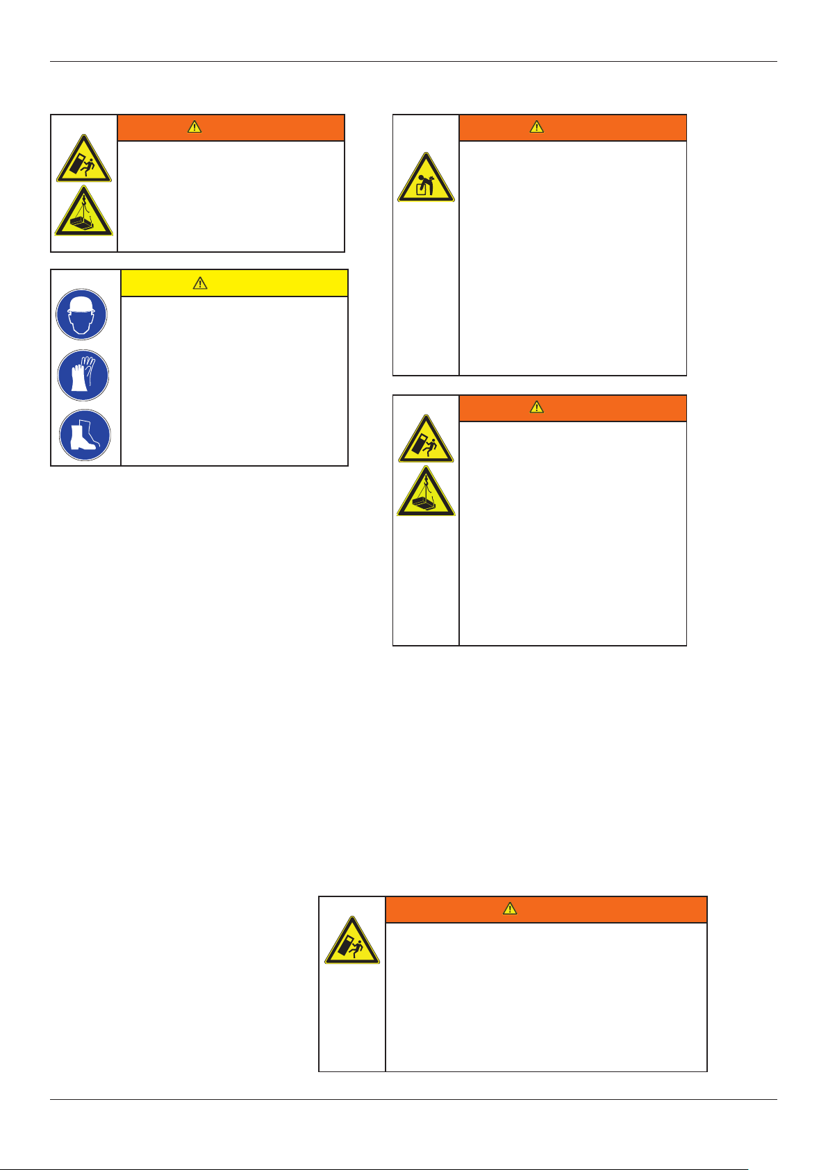
WARNING
Danger from tipping or falling
loads!
Prior to transport and handling make sure
that all components are securely assem-
bled and secure or remove all components
the fasteners of which have been loosened!
WARNING
Danger from lifting heavy loads!
Manual handling of the unit is
only permitted within the
following limits:
. max. 30 kg [max. 66 lbs] for men
. max. 10 kg [max. 22 lbs] for women
. max. 5 kg [max. 11 lbs] for pregnant
women
For weights above the given values use
suitable lifting appliances and handling
equipment!
WARNING
Danger from tipping or falling
loads!
When transporting with lifting equipment,
observe the following basic rules:
. The lifting capacity of lifting equipment
and lifting gear must be at least equal to
the unit‘s weight.
. The pump-motor unit must be
secured so that it cannot tip or fall.
. Do not stand or walk under
suspended loads!
WARNING
Danger from tipping loads!
Be sure to observe the routing of the strap belts as shown in
Fig. 4, S. 14, even if the motor is provided with attachment
points such as transport eyes or eye bolts.
These are solely designed for the separate transport of the
motor, however not for the different weight distribution that re-
sults for the mounted vacuum pump/mounted compressor, so
that the unit could tip!
CAUTION
Tipping or falling can lead to
crushing, broken bones etc.!
Sharp edges can cause cuts!
Wear personal safety equipment
(protective helmet, protective
gloves, safety shoes) during
transport!
Transport and handling by means of a
crane and strap belts is advisable.
Attach the strap belts as shown in Fig. 4, Pg. 14:
- Use two strap belts, of which one is routed under the vacuum pump/
compressor housing, and one under the fan guard.
- The strap belts should be seated securely in the undercuts so that
the unit cannot slip out.
- The belts must be sufciently long (spread angle smaller than 90°).
- Make sure that no damage is caused to any attached ttings.
Fig. 4

15
7 Installation
Installation
IN-ECO spol. s r.o.
7.1 Installation
CAUTION
Danger of crushing from unit tipping
over!
In the unmounted state, the unit can easily
tip due to its weight distribution!
Wear gloves and safety shoes!
Handle the unit with the appropriate care!
WARNING
Electrical danger!
The pump-motor unit must be installed
so that the electrical device cannot be
damaged by external inuences!
In particular, the feed pipes must be se-
curely routed, e.g. in cable ducts or in the
oor.
CAUTION
Danger of tripping and falling!
Make sure the unit does not
present a danger of tripping!
CAUTION
Danger of injuries from ying parts!
Select installation so that parts that are
thrown out through the grate if the external
fan breaks cannot hit persons!
i
CAUTION
Danger of damage to the pump-motor unit
due to overheating!
When installing the unit, make sure that
heat dissipation and cooling are not ob-
structed. The minimum distances specied
in Chapter 4.1, „Mechanical data“,
Section „Minimum distances for heat
dissipation“, Pg. 10 must be complied with.
Discharge air of other units may
not be directly sucked in again!
For the space requirement and arrangement of the holes for installing and securing the pumpmotor
unit, please see Fig. 1, Pg. 10.
For minimum clearances for heat dissipation and cooling, see Chapter 4.1, „Mechanical
data“, Section „Minimum distances for heat dissipation“, Pg. 10.
The pump-motor unit must be installed as follows:
. on level surfaces,
. with shaft in horizontal position
. on stationary (xed) surfaces or structures,
. at a maximum height of 1000 m [3280 ft] above sea level.
Observe the following when installing the pump-motor unit:
. The load bearing capacity of the base plate or the foundation must be designed
for at least the weight of the unit.
. The vibration behavior at the operating location must be taken into account.
The total vibrations of the unit are dependent on the following factors:
– the characteristic vibrations of the unit,
– the alignment and installation,
– the condition (vibration behavior) of the load-bearing surface,
– the inuences by vibrations of other parts and system components (external vibrations).
The maximum permissible value for vibrations is veff = 4.5 mm/s. To ensure proper operation and a long service life of the unit,
this value may not be exceeded. Generally, this value can be adhered to without a special foundation or a special base plate. The
points on the unit for measuring the vibration speed are shown in Fig. 5, Pg. 15.
Fig. 5: Points for measuring the vibration speed Fig. 6: Securing elements for bolting feet to supporting surface
Bolt the feet of the unit to the
suporting surface with suitable
securing elements, as
shown in Fig. 6, Pg. 15.
LR 060-H16
LR 061-H06: M = 4 x M8-6.8

16
Installation
IN-ECO spol. s r.o.
iCAUTION
Incorrect connection of the motor can lead to
serious damage to the unit!
Observe the motor rating plate. It is imperative that the operating conditions correspond to the data given on the rating
plate!
Deviations permissible without reduction in performance:
>±5 % voltage deviation
>±2 % frequency deviation
Make the connection in accordance with the circuit diagram in the terminal box. Connect the protective conductor.
>Use suitable cable lugs when doing so
>The electrical connection must be permanently safe
For motor overload protection:
> Use motor circuit breakers.
>Set the motor circuit breakers to the nominal current spe-
cied on the rating plate.
For supply by converter:
>High-frequency current and voltage harmonics in the mo-
tor supply cables can lead to emitted electromagnetic
interference.
>Use shielded supply cables, whereby the shield must be
installed on both sides
7.2 Electrical connection (motor)
The electrical connection must be carried out as follows:
- according to the applicable national and local laws and regulations,
- according to the applicable systemdependent prescriptions and requirements,
- according to the applicable regulations of the utility company.
DANGER
Electrical danger!
Malpractice can result in severe
injuries and material damage!
DANGER
Electrical danger!
Before beginning work on the unit or system, the
following measures must be carried out:
. Deenergize
. Secure against being switched on again.
. Determine whether deenergized.
. Ground and short-circuit.
. Cover or block off adjacent energized parts.
WARNING
Danger due to gauge pressure and vacuum!
Danger due to escaping uid!
Before beginning work on the unit or system:
. Interrupt supply of operating liquid.
. Bleed lines and vacuum pump/compressor
(depressurize).
WARNING
Electrical danger!
Clearance between bare live parts and between bare
live parts and ground: at least 5.5 mm [0.217“] (at a
nominal voltage of Vn ≤ 690V)
Make sure there are no protruding pieces of wire!
WARNING
Electrical danger!
The terminal box must be free from
- foreign bodies
- dirt
- a humidity
Terminal box cover and cable entries must be tightly
closed so as to make them dustproof and waterproof.
Check for tightness at regular intervals.
DANGER
Electrical danger!
The electrical connection may be carried out by
trained and authorized electricians only!

17
Installation
IN-ECO spol. s r.o.
To prevent foreign bodies from entering the unit, all connections are sealed off when delivered.
Do not remove the sealing plugs until immediately before connecting the pipes/hoses.
For the arrangement of the pipe/hose connection, see Fig. 7, Pg. 17. The pumped gases/vapors are sucked in via
the inlet connection (see Chapter 7.3.1,Pg. 18) and discharged via the discharge connection ((see Chapter 7.3.2, Pg.
18). For operation the unit must be continuously supplied with operating liquid. This is fed in via the operating-liquid
port (Chapter 7.3.3, Pg. 26) and discharged together with the pumped gases/vapors through the discharge connecti-
on.
Fill with operating liquid:
When and how the pump-motor unit must be lled with operating liquid the rst time is dependent on the operating
mode:
. For self-priming operation: During installation.
. For operation with operating-liquid feed: After completing installation
For self-priming operation you now pour operating liquid into the working space of the pump-motor unit before you
connect the pipes/hoses to the unit. To do this, pour operating liquid into the open inlet connection, discharge connec-
tion or operating-liquid port. For proper lling quantities, see Chapter 4.3, „Operating conditions“, Section „Operatingli-
quid lling amount for priming“, Pg. 11. Then attach the pipes/hoses to the unit as described in the following.
7.3 Connecting pipes/hoses (vacuum pump/compressor)
WARNING
Danger due to gauge pressure and vacuum!
Danger due to escaping uid!
. During operation, connected pipes and vessels are
pressurized or vacuumized!
. Make sure that all connections are sufciently tight!
Use only pipes and vessels of sufcient strength!
Obr. 7: Pipe/hose connection of vacuum pump/compressor
NOTICE
Attach pipes/hoses free of mechanical tensions.
Support the weight of the pipes/hoses.
iCAUTION
If the unit is run dry, the mechanical seal will
be destroyed in a matter of seconds!
DO NOT switch on as long as the unit is not
lled with operating liquid!
1 3
31
4
57
26
1) OUTPUT of air and suction liquid
2) Connection of operating liquid (water temperature
max. 35 °C, optimal temperature is 15°C)
3) INPUT of suction vacuum
4) Connection of vacuum safety valve
5) Discharge (threaded connector)
6) Connection of manometer
7) Cavitation protection (noise reduction)

18
Installation
IN-ECO spol. s r.o.
iCAUTION
The tightening torque for pipe
connections on intake and
discharge connections may not
exceed 100 Nm [73.8 ft lbs]!
iCAUTION
The tightening torque for pipe
connections on intake and
discharge connections may not
exceed 100 Nm [73.8 ft lbs]!
7.3.1 Inlet connection
The inlet connection (Fig. 7, Pg. 17) is marked with an
arrow pointing downward (↓).Connect the inlet pipe
here. The pumped gases/vapors are sucked in via this.
7.3.2 Discharge connection
The discharge connection (Fig. 7, Pg. 17) is marked
with an arrow pointing upward (↑). Connect the dis-
charge pipe here. Both the pumped gases/vapors and
the operating liquid are discharged via this pipe.
7.3.3 Operating-liquid port
The operating-liquid port (Fig. 7, Pg. 17) is located between the discharge and
inlet connection. Connect the feed pipe for the operating liquid here.
iNOTICE
For operating liquid with impurities:
> Install a lter, screen or separator in the
supply line if necessary. i
NOTICE
In case of operating liquid with a high lime
content:
. Soften operating liquid OR
. Decalcify pump-motor unit regularly (see
Chapter 11.1, „Maintenance“, Pg. 26).
i
NOTICE
To prevent installation residues (e.g. welding
spatter) from entering the unit, a start-up
screen should be installed in the inlet pipe for
the rst 100 operating hours.
19
Commissioning
IN-ECO spol. s r.o.
8 Commissioning
8.1 Preparation and start-up
If a shut-off device is installed in the discharge pipe: Make sure that the unit CANNOT be operated
with the shut-off device closed.
Fill with operating liquid:
When and how the pump-motor unit must be
lled with operating liquid the rst time is
dependent on the operating mode:
> For self-priming operation:
During installation.
> For operation with operating-liquid feed:
After completing installation.
For operation with operating-liquid feed, you now ll the working area of the unit with
operating liquid. To do this, open the respective stop valve for approx. 20 sec.:
> For non-automatic operation:
Stop valve (Fig. 11, Pg. 22, item 4).
> For automatic operation: Stop valve in the bypass pipe(Fig. 12, Pg. 22, item 4a).
Then proceed with commissioning as described in the following.
iNOTICE
Maximum permissible quantity of water entrai-
ned via the inlet connection:
See Fig. 13, Pg. 22
WARNING
Danger due to gauge pressure and vacuum!
Danger due to escaping uid!
Danger due to rotating parts!
The pump-motor unit may only be put into operation
when the following conditions are met:.
- Fan guard and vacuum pump/compressor housing
are mounted.
- The lines to the discharge connection, inlet con-
nection and operating-liquid port are
attached.
- The lines and connections have been tested for
strength and leaks.
iCAUTION
If the unit is run dry, the mechanical seal will
be destroyed in a matter of seconds!
DO NOT switch on as long as the unit is not
lled with operating liquid!
iCAUTION
If the pumped gases/vapors discharged on the
pressure side are passed on, then it must be
ensured that the maximum discharge pressure
of 1.1 bar abs. [16.0 psia] is not exceeded!
20
Commissioning
IN-ECO spol. s r.o.
Check connections of the pipes/hoses for leaks.
Check direction of rotation:
> The direction of ow of the pumped gases/vapors is marked with arrows on the intake and discharge connection.
> The intended direction of shaft rotation is marked with an arrow on the motor mounting adapter between the intake
and discharge connection, as well as with an arrow on the fan guard.
> The pump-motor unit may not be allowed to run dry! Have you lled it with operating liquid
beforehand (during or after installation)?
provozního režimu agregátu:
See sections „Fill with operating liquid“ ,Pg. 17 a Pg. 18.
> Briey switch on pump-motor unit.
> Compare the actual direction of rotation of the external fan with the intended direction of shaft rotation as indicated
with the arrows.
> Switch off pump-motor unit again.
> If necessary, reverse the direction of rotation of the motor.
WARNING
Danger due to gauge pressure and vacuum!
Danger due to escaping uid!
Before beginning work on the unit or system:
. Interrupt supply of operating liquid.
. Bleed lines and vacuum pump/compressor (depres-
surize).
DANGER
Electrical danger!
The electrical connection may be carried out by trai-
ned and authorized electricians only!
DANGER
Electrical danger!
Before beginning work on the unit or system, the
following measures must be carried out:
- Deenergize.
- Secure against being switched on again.
- Determine whether deenergized.
- Ground and short-circuit.
- Cover or block off adjacent energized parts.
See Fig. 8, Pg. 20.
Here the following must be watched:
> The pump-motor unit must be pre-throttled on the inlet side. This means a vacuum of at least 900 mbar abs. [13.1
psia] must be present in the inlet pipe (Item B) at switchon.
> During switch-on, the liquid level in the feed pipe (Item A) and in the reservoir (Item C) respectively must be at the
same level as the center of the unit shaft (Item 1).
> During operation the liquid level in the reservoir (Item C) may not drop below approx. 1 m [3.28 ft] below the center
of the unit shaft (Item 1).
Starting the pump-motor unit:
> Switch on the unit.
> The operating liquid is sucked in.
A Feed pipe for operating liquid
B Inlet pipe
C Reservoir for operating liquid
1 Required liquid level when switching on
2 Min. liquid level during operation
900 mbar abs
13,1 psa
A B
1
2
≤1m
≤ 3,28 ft
8.2 Self-priming operation
Fig. 8: Self-priming operation
This manual suits for next models
1
Table of contents
Other IN-ECO Water Pump manuals

Popular Water Pump manuals by other brands


Nordson
Nordson High Flow FB instruction sheet

Concentric
Concentric 4F649 Operating instructions & parts manual

Grundfos
Grundfos BMQE 15 Product guide

SIP
SIP 04919 user manual

Ribimex
Ribimex Ribiland PRPVC751V User and maintenance manual

Grundfos
Grundfos Unilift KP 150 Installation and operating instructions

Craftsman
Craftsman 390.2514 owner's manual

BIANCO PUMPZ
BIANCO PUMPZ BIA - AUTOSUB user manual

Sears
Sears CRAFTSMAN 390.2521 owner's manual

Wilo
Wilo Stratos PARA-C Installation and operating instructions

PCB Piezotronics
PCB Piezotronics 108A04 Installation and operating manual

Pentair
Pentair HYDROMATIC H3H Installation and service manual