In Light IN-0109-2 Series User manual

1
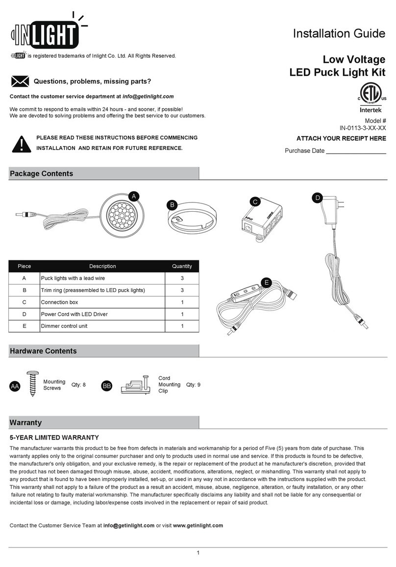
Package Contents
Power Rocker Switch CCT Rocker Switch
Piece Quantity
A 1
B 1
C 1
D 1
E 1
Hardware Contents
Wood
Screw
Warranty
3-YEAR LIMITED WARRANTY
NOTE:
Hardware not shown to actual size.
Description
Qty.2
Fixture
Power Cord
Linking Cord
End-to-End Connector
Screw Cap
B
C
DE
AA
A
We commit to respond to emails within 24 hours - and sooner, if possible!
We are devoted to solving problems and offering the best service to our customers.
Questions, problems, missing parts?
PLEASE READ THESE INSTRUCTIONS BEFORE COMMENCING
INSTALLATION AND RETAIN FOR FUTURE REFERENCE.
is registered trademarks of Inlight Co. Ltd. All Rights Reserved.
The manufacturer warrants this product to be free from defects in materials and workmanship for a period of Three (3) years from date of purchase. This
warranty applies only to the original consumer purchaser and only to products used in normal use and service. If this products is found to be defective, the
manufacturer's only obligation, and your exclusive remedy, is the repair or replacement of the product at he manufacturer's discretion, provided that the
product has not been damaged through misuse, abuse, accident, modifications, alterations, neglect, or mishandling. This warranty shall not apply to any
product that is found to have been improperly installed, set-up, or used in any way not in accordance with the instructions supplied with the product. This
warranty shall not apply to a failure of the product as a result an accident, misuse, abuse, negligence, alteration, or faulty installation, or any other failure not
relating to faulty material workmanship. The manufacturer specifically disclaims any liability and shall not be liable for any consequential or incidental loss
or damage, including labor/expense costs involved in the replacement or repair of said product.
Installation Guide
Edge-lit Technology
Under Cabinet Fixture
Model #
IN-0109-2-XX
IN-0109-4-XX
ATTACH YOUR RECEIPT HERE
Purchase Date __________________

2
Drill Phillips
Screwdriver
Safety Information
WARNING TO REDUCE THE RISK OF FIRE, ELECTRIC SHOCK OR INJURY TO PERSONS:
RISK OF ELECTRIC SHOCK RISK OF FIRE
Pre-Installation
PLANNING INSTALLATION
Compare all parts with the parts listed in the Package Contents and Hardware Contents sections. If any part appears missing or damaged, do not install or use
this light. Contact customer service
TOOLS REQUIRED
Drill
DIMMABLE FUNCTIONALITY
Integrated driver is dimmable with most regular dimmers. Following dimmers tested to be compatible with this fixture, dimming range up to: 10%-100%.
If you are unfamiliar with electrical installations, it is recommended you have a qualified electrician do your installation.
MAGNETIC LOW VOLTAGE
***CONSULT A LOCAL LICENSED ELECTRICIAN OR ELECTRICAL CONTRACTOR IF YOU ARE NOT SURE ABOUT THE INSTALLATION.***
MAX. LOAD
600 W
450 W
600W
600W
300W
600W
600W
PART NO.
DV-600P
MANUFACTURER
LUTRON
LUTRON
LUTRON
LUTRON
DVLV-600P
DVCL-153P
MACL-153M
DV-603PG-WH
TYPE
INCANDESCENT / HALOGEN
MAGNETIC LOW VOLTAGE
INCANDESCENT / HALOGEN
LUTRON
CASETA WIRELESS PD-6WCL-WH 300WINCANDESCENT / HALOGEN /CFL /LED
INCANDESCENT / HALOGEN /CFL /LED
WARNING
LEVITON
LUTRON
INCANDESCENT /CFL /LED
LEVITON IPE04
6674
INCANDESCENT / HALOGEN
Flat-headed
Screwdriver
- NOT INTENDED FOR RECESSED INSTALLATION IN CEILINGS OR
SOFFITS.
- TO PREVENT FIRE DANGER, DO NOT RUN CORD BEHIND WALLS,
CEILINGS, SOFFITS, OR CABINETS WHERE IT MAY BE
INACCESSIBLE FOR EXAMINATION. CORDS SHOULD BE VISUALLY
EXAMINED PERIODICALLY AND IMMEDIATELY REPLACED WHEN
ANY DAMAGE IS NOTED.
- DO NOT MOUNT OVER SINKS OR STOVES.
- EXTENDABLE UP TO 20 UNITS MAXIMUM.
- FOR ITEM IN-0109-2-XX, DO NOT INSTALL IN A COMPARTMENT
SMALLER THAN 12 INCHES BY 3/4 INCHES BY 2 1/8 INCHES.
- FOR ITEM IN-0109-4-XX, DO NOT INSTALL IN A COMPARTMENT
SMALLER THAN 16 INCHES BY 3/4 INCHES BY 2 1/8 INCHES.
- DO NOT USE IN WET LOCATIONS.
- USE INDOORS ONLY.
- USE ONLY INSULATED STAPLES OR PLASTIC TIES TO
SECURE THE CORDS.
- ROUTE AND SECURE THE CORDS SO THAT THEY WILL
NOT BE PINCHED OR DAMAGED.
- DO NOT ATTEMPT TO INSTALL WHILE PLUGGED IN.
NO SERVICEABLE PARTS
NON-REPLACEABLE LEDS
LED LIGHT OUTPUT IS STRONG ENOUGH TO INJURE HUMAN EYES.
PRECAUTIONS MUST BE TAKEN TO PREVENT LOOKING DIRECTLY
AT THE LEDS WITH UNPROTECTED EYES FOR MORE THAN A FEW
SECONDS.
FOLLOW ALL NATIONAL ELECTRIC CODES (NEC) AND LOCAL CODES.

3
Power Rocker Switch
CCT Rocker Switch
OFF ON
Warm White
2700K
Bright White
4000K
Preparing the light for installation Securing the power cord
- Fixture must be mounted within 6 ft. of an outlet. - Attach the power cord to the "INPUT" receptacle on the side
of the fixture.
-
Plug the power cord into the power supply
Plug-in Installation (Skip this step if using Hardwire Installation)
1 2
3
WARNING:
DO NOT plug the power cord into the power supply
before finishing the installation."
Use a flathead screwdriver to carefully pry off the plastic
INPUT receptacle that covers the power port on the fixture.
Note:
The power cord can only be connected to the “INPUT”
receptacle, so make sure the right receptacle is identified. The 2
receptacles are designed to only accept a specific plug. Do not
force connection, it should snap in easily.
-Follow the directions for mounting on page 4.
-Once mounting is completed, plug the cord into a 120VAC/60Hz power supply.
-The unit can now be turned on with the power switch.

4
Mounting Installation
Preparing the light for installation Mounting the light fixture
- DO NOT ATTEMPT TO INSTALL LED LIGHT BAR WHILE
PLUGGED IN.
- Attach the light to the desired surface using the fixture mounting
screws (AA). Tighten the screws securely.
- Make sure the mounting surface is capable of supporting the
fixture.
-
Attaching the screw caps and check installation
- Install the 2 screw caps (E).
- Make sure that all unused receptacle ports on the ends of the fixture are safely protected with PLASTIC RECEPTACLE CAP (two provided with
each fixture).
- Restore power to the electrical circuit at the service panel and check installation.
- Turn on the wall switch to light the fixture.
- The unit can now be turned on with the power rocker switch (flip to ON position).
1 2
3
Power Rocker Switch
CCT Rocker Switch
OFF ON
Warm White
2700K
Bright White
4000K
AA
E
Note: The fixture mounting screws are suitable for cabinet
bottoms 3/8 in. or thicker. Use shorter screws for thinner cabinet
bottoms.
Note: In some installations it may be desirable to drill a pilot hole
for the screws. Place the fixture in the desired position and drive
mounting screws a small amount to impart a small reference point
for drilling. Using a 1/16” drill bit, drill pilot holes for the screws.
Locate position where the fixture is to be mounted. Make
sure the 6 ft. power supply cord will reach the nearest electrical
outlet.

5
Installing the junction box (sold separately) Connecting the wires
- Discard power cord if Hardwire Installation is used. - Follow the directions for connecting the wires (BLACK to BLACK,
WHITE to WHITE), installation instruction is included in the
package of junction box.
- Turn power OFF from the electrical panel before starting
the installation.
- Ensure the wire nuts are tight and carefully place the spliced
wires back into the junction box.
- Mount the junction box following directions given in the junction
box package.
-
-
-
-
-
-
Hardwire Installation (Skip this step if using Plug-in Installation to power unit)
1 2
3
Junction box (sold separately)
Black Wire
White Wire
Power Rocker Switch
CCT Rocker Switch
OFF ON
Warm White
2700K
Bright White
4000K
Junction box (sold separately)
Installing the under cabinet fixture
Follow the directions above to mount the under cabinet fixture.
Use a flathead screwdriver to carefully pry off the plastic INPUT receptacle that covers the power port on the fixture. Attach the linking cord
to the "INPUT" receptacle on the side of the fixture.
Connect linking cord to the junction box.
Check installation, then restore power to the electrical circuit at the service panel.
Turn on the switch to light the fixture.
The unit can now be turned on with the power switch.

6
Joining multiple fixtures
With power disconnected, each additional fixture (not included) should be mounted in the same manner as the first installed fixture.
Installation instructions using linking cord
-
-
-
-
-
Installation instructions with end-to-end connector
-
-
-
-
-
-
-
WARNING: LINKABLE 20 UNITS MAXIMUM.
NOTE:Each light can be individually operated by the on/off
switch located on each fixture.
WARNING: IN MULTIPLE FIXTURE INSTALLATIONS DO NOT ELECTRIFY FIXTURE GROUP UNTIL ALL ELECTRICAL CONNECTIONS HAVE BEEN
SECURELY MOUNTED. PLASTIC CAP MUST BE INSTALLED IN ALL OPEN PORTS AT THE COMPLETION OF INSTALLATION.
NOTE: Each light can be individually operated by the on/off switch located on each fixture.
WARNING: LINKABLE 20 UNITS MAXIMUM.
WARNING: DO NOT USE JUMPER CORD AS A MEANS TO TURN FIXTURES ON AND OFF.
1
2
Hold the fixture in the desired mounting location allowing approximately
2 ½” clearance for interconnect cables. Drive mounting screws into cabinet
surface, mount the fixture to surface by aligning screws to keyholes and
sliding over until the narrow ends of the keyhole slots are under the heads
of the wood screws.(ref. page. 4 mounting installation)
Carefully remove the plastic caps that cover the power
port on the fixtures.
The linking cord is fitted with a distinct cord connector plug at each
end and will only connect one way. Try inserting one end of the
linking cord into a power port (input/output receptacle), if it fails to
connect, try the other end. Do not try to force the plug into the port.
Make sure the plugs on both ends are fully inserted into ports on both fixtures.
If this will be an end fixture in a run, use plastic cap to cover any connector
not being used.
Turn on power.
Carefully remove the plastic caps that cover the power
port on the fixtures.
The End to End connector is fitted with a distinct cord connector
plug at each end and will only connect one way. Try inserting one
end of the End-to-End connector into a power port (input/output
receptacle), if it fails to connect, try the other end.
Do not try to force the plug into the port.
Hold new fixture to the same level of installed fixture, align the two
fixtures by meeting the ene-to-end connector with a power port
Push new fixture to existing fixture until fixtures are flush and
connectors snap together. Fixtures should fit fully and squarely
end-to-end when mounting is complete.
Drive mounting screws into cabinet surface until fixture is secure.
If screws are difficult to install, mark holes, remove fixture and
drill 1/16” maximum pilot holes. (ref. page. 4 Mounting Installation)
If this will be an end fixture in a run, use plastic cap to cover any
connector not being used.
Turn on power.

7
Accessories
Junction box (Plastic)
Used to power under cabinte fixtures using linking
cord. Includes ON/OFF switch.
End-to-End connector
Used to join fixtures together.
Linking Cord
Used to join fixtures together.
IN-0501-3: Junction Box, White
IN-0501-3-BZ: Junction Box, Bronze
JC2-ETE-WH: End-to-End connector, White
JC2-ETE-BK: End-to-End connector, Black
Troubleshooting
This LED light provides low maintenance service with no bulbs to change. Clean the surface of fixture with a damp cloth. Do not use abrasive materials such
as scouring pad or powders, steel wool or abrasive paper.
Problem Possible Cause Corrective Action
Fixture doesn't light. 1. Power is off.
2. Defective wall Switch.
1. Check if power supply is on.
2. Replace switch.
Fuse blows or circuit breaker trips when light is turned on. 1. Overloaded circuit
2. Short circuit.
Check the wire connections, discontinue use and
call customer service.
Lights ficker during dimming Dimmer is not compatible with the
fixture. Replace with a dimmer from the compatible list.
Lights ficker fixture is not working properly. If a constant voltage is measured, discontinue use
and call customer service.
Power Cord
Used to convert fixtures from hardwire to direct
plug-in units.
JC2-12-WH: 12" Linking Cord, White
JC2-24-WH: 24" Linking Cord, White
JC2-32-WH: 32" Linking Cord, White
JC2-60-WH: 60" Linking Cord, White
JC2-12-BK: 12" Linking Cord, Black
JC2-24-BK: 24" Linking Cord, Black
JC2-32-BK: 32" Linking Cord, Black
JC2-60-BK: 60" Linking Cord, Black
PC4-24-WH: 24" Power Cord, White
PC4-36-WH: 36" Power Cord, White
PC4-72-WH: 72" Power Cord, White
PC4-24-BK: 24" Power Cord, Black
PC4-32-BK: 36" Power Cord, Black
PC4-72-BK: 72" Power Cord, Black

8
Questions, problems, missing parts? Before returning to the store,
contact Inlight Customer Service
Retain this manual for future use.
is a trademark of Inlight Co. Ltd.
V. 2019
This manual suits for next models
1
Table of contents
Other In Light Lighting Equipment manuals
Popular Lighting Equipment manuals by other brands
Vivaria
Vivaria Nebula X-3 operating instructions

Commercial Electric
Commercial Electric 54655241 Use and care guide

hudson valley
hudson valley L1054 installation instructions
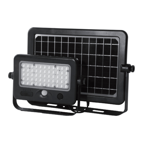
Somogyi Elektronic
Somogyi Elektronic home FLP 1100 SOLAR instruction manual
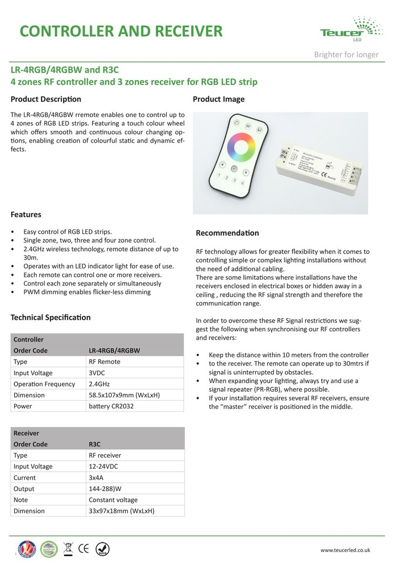
TEUCER
TEUCER LR-4RGB Technical specification
Ovation
Ovation Solar Panel 150T user manual
