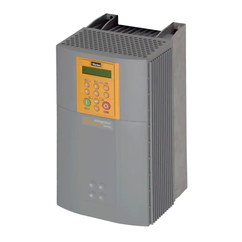
In-situ Con TROLL PRO DC-L User manual

Installation Manual
Con TROLL®PRO Installation Manual
Information subject to change without notice. In-Situ, In-Situ logo, Baro Merge, BaroTROLL, HERMIT, HydroVu™, iSitu, Pocket-Situ, RDO,
RuggedCable, RuggedReader, SmarTROLL™, TROLL, VuSitu, and Win-Situ are trademarks or registered trademarks of In-Situ Inc.©2009-
2013. All rights reserved. This product may be covered by patents identified at www.in-situ.com/patents
0085660 | 2018-08-23

2
Copyright © 2009-2013 by In-Situ All rights reserved.
This document contains proprietary information which is protected by copyright. No part of this document may be
photocopied, reproduced, or translated to another language without the prior written consent of In-Situ
Mailing and Shipping
Address: Phone: 970-498-1500 (international & domestic)
In-Situ
221 East Lincoln Avenue
Fort Collins, CO 80524
U.S.A.
Fax: 970-498-1598
Internet: www.in-situ.com
Support: 800-446-7488 (U.S.A. & Canada)
In-Situ makes no warranty of any kind with regard to this material, including, but not limited to, its fitness for a particular
application. In-Situ will not be liable for errors contained herein or for incidental or consequential damages in connection with
the furnishing, performance, or use of this material.
In no event shall In-Situ Inc. be liable for any claim for direct, incidental, or consequential damages arising out of, or in
connection with, the sale, manufacture, delivery, or use of any product.
In-Situ and the In-Situ logo, Win-Situ, TROLL, Baro Merge, BaroTROLL, HERMIT, HydroVu™, iSitu, Pocket-Situ, RDO,
RuggedCable, RuggedReader, SmarTROLL™, TROLL, VuSitu™, and Win-Situ are trademarks or registered trademarks of
In-Situ Inc. Microsoft and Windows are registered trademarks of Microsoft Corporation. Pentium is a registered trademark of
Intel. Tefzel and Delrin are registered trademarks of E. I. DuPont de Nemours and Company. Viton is a registered trademark
of DuPont Dow Elastomers. Kellems is a registered trademark of Hubbell Inc. Alconox is a registered trademark of Alconox
Company. Lime-A-Way is a registered trademark of Reckitt Benckiser. Android is a trademark of Google Inc. iPod and
iPhone are trademarks of Apple Inc., registered in the U.S. and other countries. The Bluetooth word mark and logos are
registered trademarks owned by the Bluetooth SIG, Inc. and any use of such marks by In-Situ Inc. is under license. NIST is a
registered trademark of the National Institute of Standards and Technology, U.S.A. Other brand names and trademarks are
property of their respective owners.
The presence of the Waste Electrical and Electronic Equipment (WEEE)
marking on the product indicates that the device is not to be disposed via
the municipal waste collection system of any member state of the European
Union.
For products under the requirement of WEEE directive, please contact your
distributor or local In-Situ office for the proper decontamination
information and take back program, which will facilitate the proper
collection, treatment, recovery, recycling, and safe disposal of the device.
0085660 | 2018-08-23

3
Table of Contents
1 Safety 5
Hazard Symbols that Appear in the Manual 5
Precautionary Labels that many Appear on the Product 5
2 Overview 6
Available Models 6
Compatible Instruments 6
Box Contents 7
3 Mounting the Controller 9
Optional Mounting Kit 9
Mounting Options 10
Controller Dimensions 10
Pole Mounting 13
Wall Mounting Using Mounting Tabs 14
Wall Mounting with User-supplied Hardware 16
DIN Rail Mounting the Enclosure 17
Placing Dome Connectors and Plugs in the Enclosure 18
4 Electrical Connections 20
Power Options 20
Electro-Static Discharge (ESD) Recommendations 20
Customer-Supplied Electrical Equipment 20
Ensuring Dome Connectors are Water-Tight 20
Ensuring Good Electrical Connections 20
Relay Connections 22
Disconnecting AC Power 23
Desiccant Pack 23
5 Input/Output Connections 24
PLC Connections 24
Sensor Wiring Connections 25
Current Loop Outputs 26
Relay Connections on the I/O Board 28
Desiccant Pack 28
6 Optional Battery Box 29
Overview of Battery Box Kit 29
Additional Considerations 29
Preparing the Power Cord 29
Mount the Enclosure 29
Connect the External Battery Enclosure to the Controller Enclosure 29
Connect the Battery Terminals 30
7 Maintenance 31
Cleaning the Outside of the Enclosure 31

5
Safety
Please read this manual before unpacking or installing any part of this system.
Hazard Symbols that Appear in the Manual
Danger—Indicates a hazardous situation, which, if not avoided, will result in death or serious injury.
Note—Indicates a situation that is not related to potential injury.
Les Symboles D'advertissement Figurant Dans Le Guide
Danger—indique une situation dangereuse, qui, si elle n'est pas évitée, pourra provoquer la mort ou des blessures
sérieuses.
Note—indique une situation qui n'est pas susceptible de provoquer de blessure.
Precautionary Labels that many Appear on the Product
Important—When noted on the instrument, this symbol references the user to the manual.
Electrical Shock—When noted on the instrument, this symbol indicates a risk of electrical shock.
Protective Earth Ground—When noted on the instrument, this symbol indicates the location of protective earth ground.
Consignes De Precaution Dans Le Boitier
Important—Quand cette consigne s'affiche sur l'appareil, elle renvoie au guide
d'utilisateur.
Electrical Shock—Quand cette consigne s'affiche sur l'appareil, elle signale la
possibilité de choc électrique.
Protective Earth Ground—Quand cette consigne s'affiche sur l'appareil, elle indique l'emplacement de la prise de terre.

6
Overview
All Con TROLL PRO models contain the following items.
lNEMA 4X rated
lRobust keypad and display window
lEasy-to-use controller software
For a complete list of controller specifications See "Specifications" on page 32
Available Models
The Con TROLL PRO is available in three models.
lModel DC-L, a battery- or solar-powered controller with logging abilities. This model requires a 9-36 VDC ( ) 0.2 A
max supply as the primary power source. It is suited for remote applications and can trigger low-voltage relays.
lModel AC, a 100–240 VAC (~), 0.15 A, 50–60 Hz-powered controller capable of displaying and transmitting data.
This model is suited for applications with access to line power that do not require logging abilities. This model can
trigger low- and high-voltage relays.
lModel AC-L, 100–240 VAC (~), 0.15 A, 50–60 Hz-powered controller capable of logging, displaying, and
transmitting data. This model is suited for applications with access to line power that require logging abilities. This
model can trigger low- and high-voltage relays.
Compatible Instruments
The Con TROLL Pro is compatible with these instruments:
lAll Level TROLLS (400, 500, 700, 700H)
lRugged TROLL 200
lAqua TROLL 100, 200, and 400
lRDO Pro-X
lRDO Titan

7
Box Contents
Remove the controller from the shipping box. The shipping box should contain the following items.
lController (1)
lController plugs (5)
lDome connectors (3)
lO-rings (6)
lLarge lock nuts (6)
lSealed desiccant pack (1) that will be placed in the installed controller.
lOpened desiccant pack (1) that protected the instrument during shipping. Discard after opening the controller.
After verifying that the contents of the box are complete, place the controller back in the box for
transport to the installation site.
Figure 2.1 Internal view of DC model

8
Figure 2.2 Internal view of AC model

9
Mounting the Controller
Danger—Only properly trained and qualified personnel should install the controller described in this manual. This
instrument should be installed for use in non-hazardous locations only.
Danger—L'installation de l'appareil “controller” décrite dans le guide d'utilisateur doit impérativement être réalisée par
des personnes qualifiées. L'installation de cet appareil est seulement prescrite pour des emplacements sans risques.
Optional Mounting Kit
The mounting kit contains the following items.
lTwo stainless mounting brackets
lTwo 1.5—3.5 in. diameter hose clamps
lOne package containing mounting tabs (4), nuts (4), and screws (4)
lDIN rail mounting brackets
The nuts and screws supplied with the mounting tabs are suitable for use with the mounting brackets.
Figure 3.1 Con TROLL PRO mounting kit

10
Mounting Options
Controller Dimensions
Figure 3.2 shows the controller dimensions with the lid closed.
Figure 3.3 shows the dimensions of the controller box with the lid open. It indicates where holes should be drilled for wall or
panel mounting without using the supplied mounting tabs.
Figure 3.4 shows the depth dimensions of the controller. When installing on a wall or panel, make sure to allow adequate
space for opening the enclosure door or making electrical connections.
Figure 3.2 Controller dimensions with lid closed

11
Figure 3.3 Controller dimensions with lid open

12
Figure 3.4 Side view dimensional drawings

13
Pole Mounting
1. Remove the 4 nuts and 4 screws from the mounting kit.
2. With the enclosure open, drop 1 nut into each drilled corner of the box.
3. Use a screwdriver to push the nut down and set it in place.
Figure 3.5 Placing the nut in the enclosure
4. Place the 2 brackets on the back of the enclosure so that the flanges on the brackets will point toward the ground.
5. Attach the mounting brackets to the enclosure using 2 screws for each bracket. Make sure that the screws
properly thread into the nuts that you seated in steps 2 and 3.
6. Place 2 hose clamps over the mounting pole and tighten them until they are almost secure.
7. Place the flanges from the mounting bracket into each of the hose clamps.
8. Completely tighten the hose clamps until the entire controller unit is secure on the pole.

14
Figure 3.6 Attaching the mounting brackets
Figure 3.7 Back and side view of pole-mounted controller
Wall Mounting Using Mounting Tabs
The optional mounting kit contains a set of wall mounting hardware that includes four screws, nuts, and tabs for mounting the
controller to a wall or panel. Follow the instructions included with the mounting tab hardware to attach the tabs.

15
Figure 3.8 Back view of controller with tabs

16
Wall Mounting with User-supplied Hardware
You can supply your own mounting hardware and attach the controller to a wall. Use a screw that is best suited for your wall
material.
Figure 3.9 Back view of Con TROLL PRO

17
Figure 3.10 Template for wall mounting with user-supplied hardware
DIN Rail Mounting the Enclosure
Each rail mount clip is secured to the enclosure with a supplied #6 screw.
1. With the enclosure open, drop 1 screw into each drilled corner of the box.
2. Use a long screwdriver to push the screw through the back of the enclosure.
3. Place the DIN clip on the top of the enclosure. See Figure 3.12 .
4. Use a long screwdriver to tighten the screw to the clip.
5. Repeat steps 2-4 for the remaining screw and clip.
6. Mount on a DIN rail.

18
Figure 3.11 Placing the screw in the enclosure
Figure 3.12 Securing the screw to the DIN clip
Placing Dome Connectors and Plugs in the Enclosure
When installed as directed, this product is rated IP-67 and can withstand temporary immersion in up to 1 meter of water. To
meet the IP-67 rating, the following conditions must be met.
lThe lid must be completely closed and screwed down.
lThe 6 ports must be plugged with either cord grips and cables, port plugs, or a combination of both.
lAdditionally, O-rings must be used as described below.
Attach plugs and dome connectors to the enclosure using the following steps.
1. Place a large O-ring over the threaded end of the plug or dome connector.
2. Screw the threaded end of the plug or dome connector through the bottom of the enclosure. Tighten it to “snug” and
then an turn it an additional half turn.
Do not over tighten.
3. Inside the enclosure, place the lock nut, concave-side-down, over the threaded end of the plug or dome connector
and tighten with a flat-head screwdriver and mallet. Tighten the lock nuts so that there is approximately 1 thread
showing above the nut.
4. Screw the dome nut onto the threaded connector. Tighten it to “snug” and then turn it an additional half turn.

19
Do not over tighten.
5. Thread sensor or electrical cables through the dome connectors for later wiring by a qualified electrical technician.
Tighten to approximately 15 in-lbs of torque.
Figure 3.13 Controller box hardware
Figure 3.14 Attached port plug (left) and attached dome connector (right)

20
Electrical Connections
Danger—Only properly trained and qualified personnel should install the controller described in this manual. This
instrument should be installed for use in non-hazardous locations only.
Danger—L'installation de l'appareil “controller” décrite dans le guide d'utilisateur doit impérativement être réalisée par
des personnes qualifiées. L'installation de cet appareil est seulement prescrite pour des emplacements sans risques.
Power Options
The Con TROLL PROis available with 2 power options.
lDC-powered, which requires a 9-36 VDC supply as the primary power source. This model can trigger low-voltage
(<50 V) relays only. See "Input/Output Connections" on page 24
lAC-powered, which requires a 100-240 VAC as the primary power source. This model can trigger low-voltage
relays (<50 V) through the I/O board only (See "Input/Output Connections" on page 24), and high-voltage relays
(>50 V) through the AC board only.
Electro-Static Discharge (ESD) Recommendations
Before making wiring connections, discharge any static electricity from your body before touching circuit boards and
other internal components by touching a grounded metal object.
When making wiring connections, make sure to remain properly grounded by wearing an ESD wrist strap or similar
device.
Customer-Supplied Electrical Equipment
The end user must supply the following items.
l18-12 AWG wire for electrical connections using conduit or 100-240 VAC power supply
l24-12 AWG cable for connecting relays and PLC devices
lFor hard-wired locations using conduit, a 100-240 VAC or 9-36 VDC source with over current/disconnect protection
will be provided by the end user.
lFor cord-connected plug and socket locations, approved suitable wiring to be provided by the end user.
Ensuring Dome Connectors are Water-Tight
The dome connectors that you installed must be tightened securely after sensor cable or electrical cables are routed through
them.
These dome connectors are not meant to be weight-bearing.
For best results, ensure that the following conditions are met.
lThe cable does not slide or move after the connectors are tightened.
lSufficient cable has been threaded through the connector so that secure wiring connections can be made.
lThere is no weight or force from the water pulling on the cable.
Ensuring Good Electrical Connections
To ensure that all sensors and power sources function properly consider the following recommendations.
This manual suits for next models
2
Table of contents
Popular Controllers manuals by other brands
Linear Technology
Linear Technology Analog Devices LT8708 datasheet

FIBARO
FIBARO FGPB-101 instructions
KMC Controls
KMC Controls MCP-1040 Series installation guide

Emerson
Emerson Bettis 2000 Series Installation and maintenance manual
LOCKLY GUARD
LOCKLY GUARD INGRESS user manual
NavAtlas
NavAtlas NA2BT Installation & owner's manual


