InBand Air User manual

InBand Air
Electronic Scoring Target Manual
Content:
1How to Implement an InBand Air ................................................................................................2
Composition of InBand Air...................................................................................................2
Mounting an InBand Air........................................................................................................3
Assembling the target face and the control sheet..................................................................4
Assembly of the InBand 50...................................................................................................6
2Downloading the softwares ..........................................................................................................7
Installing a USB driver..........................................................................................................7
Installing the Bluetooth®......................................................................................................7
Installing InBand Scoring software.......................................................................................9
3Using an InBand Electronic Scoring targets.................................................................................9
Launching a InBand Scoring programme .............................................................................9
Settings................................................................................................................................10
Practising with an InBand Air .............................................................................................11
Competition shooting..........................................................................................................13

1How to Implement an InBand Air
Composition of InBand Air
The basic delivery of InBand Air system contains
1. an electronic target
2. a front plate
3. a power sources
4. a target lighting device (LED)
5. a 15 metre USB cable
6. a target frame
7. a control sheet roll
8. target faces (air rifle, air pistol or hunting figures).
Optionally InBand Air may be delivered also with a Bluetooth® module.
If the InBand Air is delivered with the .22 small bore shooting option (InBand 50), it will contain
also
1. a bold front plate
2. a rubber control sheet roll
3. an extra black aiming card
4. a plastic target face (small bore rifle)
5. a wireless a Bluetooth® module.
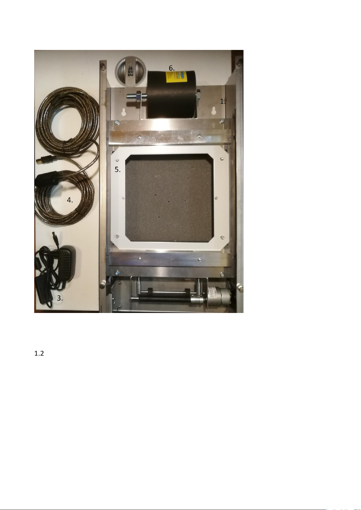
Picture 1. Composition of InBand electronics scoring target
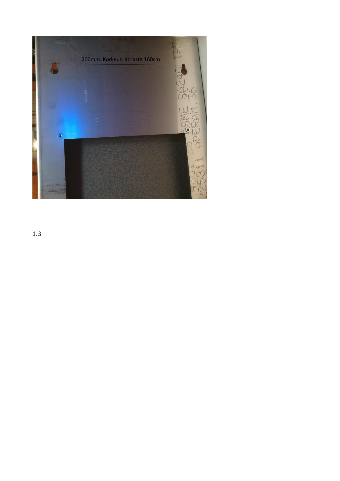
Mounting an InBand Air
An InBand Air is easy to mount on the fixed or non-fixed wall in a shooting range. On the back side
of the EST device there are two assembly holes for attaching screws. The holes are 200 mm apart.
The mounting screw should be placed 160 cm above the firing point level (normally the same
height also from the floor near target area) in order to have the target centre at a height of 140
cm.
A bullet catcher is also needed to mount your InBand Air. The normal delivery does not include a
bullet catcher. If you mount the InBand Air or InBand 50 to an old shooting range with paper
targets you can utilize old bullet catchers.
Assembling the target face and the control sheet
The easiest way to get an InBand Air ready to shoot, is to follow next steps
1. Hang an InBand Air to the mounting screws. Connect the USB and power source cables
(picture 3). Switch on the power and the illumination LED device turns dimly on.
2. Put first an air pistol target as a base target card. That will help the control sheet to move
easier. You do not need to change this normally between shooting sessions (picture 4.)
3. Assemble the control sheet roll (loose strip to the front) onto the rack on the top of the EST
device (picture 4). Slide the control sheet trough upper and lower gaps until it reaches
capstan. Then push the red capstan driving button (picture 3). Help the control sheet move
forward by one hand when pushing the button. This removes loose parts of the strip.
Tighten also nuts of the control sheet rack that the control sheet will not roll too
excessively.
4. Lay a valid target face (rifle, pistol or hunting rifle) and a metallic target fixing plate to the
target base. The target fixing plate is a self-attaching to the EST frame by small magnets.
5. Finally, hang a front plate onto the screws in the front of the EST device (picture 5) and
tighten the screws with your fingers. The InBand Air is now ready for shooting.
Picture 2. Mounting an InBand Air to the wall
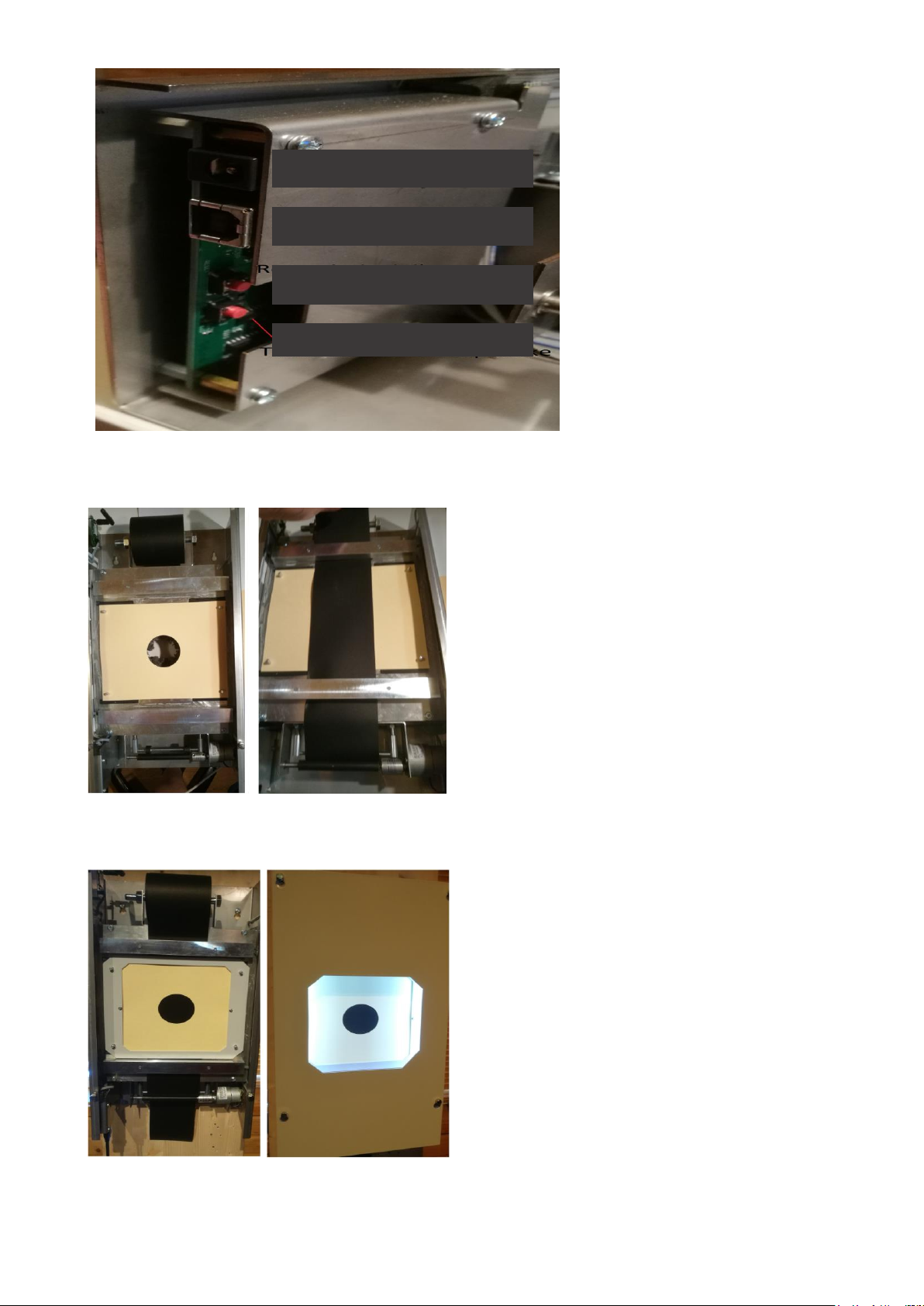
Picture 3. Connection ports and switches
Picture 4. Assembly of the base target card
Picture 5. A target face assembly on the left and a front plate assembly on the right
Power port (12 v)
USB port
Target reset button
Control sheet driver
button
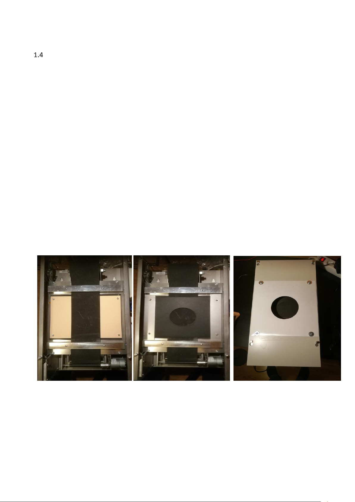
Assembly of the InBand 50
The InBand 50 EST will be assembled in a same way as a InBand Air. However, there are some
differencies when assembling the InBand 50 for metre shooting:
−Lay first an air pistol target to the bottom of the target base
−Instead of a paper control sheet in 10 metre shooting, a 2 millimetre multiusable rubber
sheet will be used
−next lay an all-black target card to the target base
−The exact location of the all-black target card is secured by the magnetic metallic bars. The
normal target fixing plate for 10 metre target faces provides too narrow space for rubber
control sheet and the rubber band would easily be stuck.
−The tightness of the rubber control sheet roll in the rack should be reasonable that the
sheet is able to run smoothly.
−The plastic target face will be attached to the bolded front plate with screws.
Picture 6. Assembling a InBand 50 for shooting. On the left base card and rubber control sheet, in
the middle rubber control sheet and an all-black aiming target and on the right a ready to use
InBand 50 electronic target.

2Downloading the softwares
Before you begin to use an InBand Air system you must download necessary softwares in your
computer (PC). These might be USB driver, Bluetooth® driver and finally InBand Scoring software.
You can find a video how to download all softwares in Youtube service:
https://youtu.be/WFoVtM9Y2oI
Take notice that the InBand software version in the video might be older than the present version.
All the details and functions are not exactly the same as in the newest software version.
Installing a USB driver
When an InBand Air (or Inband 50 m) is connected to a computer or other display with a USB
cable, a USB driver must be installed into the computer. If an internet connection is available in a
shooting range, the computer (PC) will automatically load the USB driver. Otherwise you must
download the driver when you are home or somewhere else with internet connections.
A USB driver can be downloaded and installed in the internet address:
https://drive.google.com/open?id=0B3rKx5S-sD2TQ0FNeVBHRnVXZU0
After installing a USB driver, you can proceed to install the actual InBand Scoring software and a
Bluetooth® software.
Installing the Bluetooth®
When InBand Air is used via Bluetooth®, a computer and a Bluetooth® must be paired before
shooting activities.
Bluetooth® settings is easiest done in the Windows 10 operating system by writing “bluetooth”
into the search box (picture 6) and opening the result “Settings of the Bluetooth and other
devices”.
In the setting box choose “Add Bluetooth or other device”.

Picture 7. Setting the Bluetooth® in the Windows 10 operating system.
Picture 8. Creating a Bluetooth® connection in Windows 10 operating system.
Installing InBand Scoring software
After you have loaded USB and Bluetooth® drivers, you can proceed to install the actual InBand
Scoring software.
You should download the latest version of the InBand Scoring software (VER4.3/1.4.2019) from
-www.inband.fi; Tuotteet/Products (unzip needed before final installing)
-https://drive.google.com/open?id=0B3rKx5S-sD2TYUpDNTk2WW0ySkU
3Using an InBand Electronic Scoring targets
Launching a InBand Scoring programme
Before executing an InBand Scoring software, check that the target is connected to your computer
or other display via USB cable or the Bluetooth® driver is installed. When you execute an InBand
Scoring programme, the software is automatically searching an Inband target. On the first time this
might take a while. Next time the searching time is much shorter. After TARGET STATUS turns in to
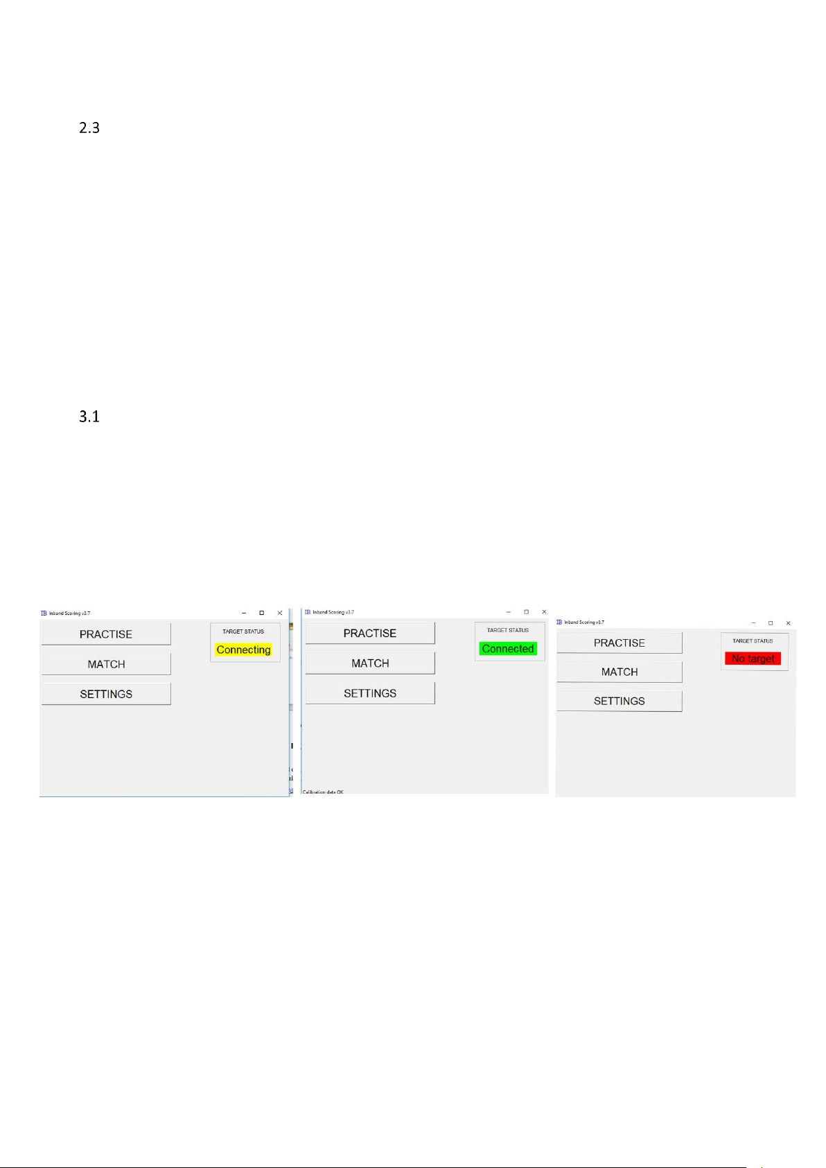
green with text “Connected”, the target is ready to use (picture 9).
Picture 9. Executing InBand Scoring program. On the left picture, software is searching (yellow
symbol “connecting”). In the middle, target is connected into computer and the system is ready to
shoot (green symbol “Connected”. On the right, the target is not found (red symbol “No target”),
and then you must check that the USB cable is connected and the target power is on.

Settings
InBand EST settings can be defined in the Settings box. These settings are saved automatically, and
software will recall them later.
Picture 10. Settings
Name:Shooters name (appears also in the result, timing and scoring list
Club: Shooting club
Series: Shooters category (f.ex age class)
Server IP: If multiple targets are used (f.ex competition), the IP address of the central computer is
indicated here. Note: familiarise yourself with InBand Range Officer software by the special manual
LANE#: Firing point number.
Shooting dist (%). A true shooting distance may be chosen by determining the relative length
compared to the official shooting distance. For example, if you are shooting with an air rifle at 7
metres, you put a number 70 (70 % of 10 metres is 7 metres)
Airpistol band move: Control sheet step in air pistol shooting. The step can be adjusted between
numbers 0 – 9. By default, number 1 runs control sheet about 1 centimetre, which is usually
adequate in training purposes. If the precision of the target is fully utilized, the control sheet steps

should be so long that there is no risk to shoot shots in the same hole. Practically speaking, the
divergence in precision is less than 1 millimetre if a bullet hits the old hole.
Air rifle band move: Control sheet step in air rifle, look previous point (air pistol)
Ilmaluodikko band move: Control sheet step in hunting rifle, look previous point (air pistol)
50m rifle band move: Rubber control sheet step in 50 metre rifle shooting. While bullet holes in
the natural rubber sheet will shrink almost all, the default number can be 0 (zero).
DIAGNOSE: This diagnosis button is normally used only in the maintenance of the EST device.
SAVE LOG FILE: With this function, you can save the log file of the previous shooting activities in
order to help analyse possible unwanted malfunctions by the manufacturer.
BACKUP FILE: This function asks user, how the back-up file of the results will be named. It is a text
file.
CLOSE: This function closes the Settings box. The settings box may be closed also by pushing the X
in the upper right corner.
LIGHT+ ja LIGHT -: The level of illumination of the target device can be adjusted between 0 – 100.
Use decimals on XXX: In every shooting discipline a user can choose whether the scoring is done
with full rings or decimals. The default is that in air rifle and 50 metre prone shooting decimals are
on.
Debug mode: Normally Debug function should be off (no X). If the Debug function is on, it will be
shown some extra features and data in a display which is beneficiary in possible trouble shooting.
Allow remote control: If this function is on (X), it is possible to control a single target remotely. This
should be on only in competitions.
Practising with an InBand Air
After the InBand target is connected (Target Status is green) to the computer, you can start
practising. The way to the shooting session begins by pushing Practise button in the main panel. In
the Practise settings window will be chosen a necessary discipline after which the Start button is
clicked.

Picture 11. Choosing a shooting discipline
Kuva 12. Inband is ready for shooting

When the InBand Scoring opens the target graphic, you can start shooting. The last shot is always
shown in red colour. The old ones in a serie are green. The target graphic is cleaned after every ten
shots. The shot figures are seen in scoring card during shooting session.
The screen can be zoomed out or in by pushing +/- buttons. A Shooter can save a hard copy of
his/her shooting with Save PDF button. The report is in pdf format. The default name of the file is
formed by shooters name, discipline and date. The file name is also possible to write according to
your own choise.
SIGHTERS ON function turns target on sighters mode with black diagonal line in upper left corner.
After you have shot enough sighters in an air pistol or a rifle (10 m or 50 m) training you can push
red RESET button to start competition series.
PRINT GROUP function makes a pdf print file of a previous shot group which you can also print out.
This function can be utilised when testing a precision of a target. Shoot first a test group of 5 into a
whole target paper target (without aiming mask). Next, print out a pdf picture. Finally put the
target paper with bullet holes over the printed paper. If target is precise, you can see the hits
through the printed paper holes. This is how the factory test is done before you have got your
InBand electronic target.
When you are finished with your training session, you can push QUIT button. You can stop training
session also by pushing X in the upper right corner of the window.
Competition shooting
Match operation will not be updated in coming InBand Scoring versions any more. It will be
possible that it will be taken out of the individual software options. Although its function is a
Match, it not intended for competition management, but only competitive training.
Picture 13. Choose your discipline and push START MATCH button

In Match pick-up window (picture 12) you determine your shooting discipline, number of shots and
shooting time. After this press START MATCH button.
The sighters are first done after pushing START SIGHTERS. After this starts 15 minutes sighting time
which may not be interrupted.
After the sighting time is ended, you can start competition (competitive shooting) by pushing
START MATCH button.
Picture 14.Sighters will be started by pushing START SIGHTERS button.
Picture 15. Competition starts by pushing START MATCH button.
Table of contents


