INCINOLET 4100 Series Manual

INSTALLATION IMAINTENANCE MANUAL
120 VOLTS (SN 57200–) 240 VOLTS (SN 41000–)
23 / V2

MANUFACTURE’S STATEMENT.................................................. 1
HOW TO USE INCINOLET............................................................ 2
HOW INCINOLET WORKS ........................................................... 2
HOW TO INSTALL INCINOLET..................................................... 3-4
TIPS FOR BEST VENTING ........................................................... 5
UNDERSTANDING ELECTRICAL OPERATION............................ 6
CARE & CLEANING..................................................................... 7
TROUBLESHOOTING .................................................................. 8-9
PART SCHEMATIC....................................................................... 10
MAINTENANCE & REPAIRS........................................................11-12
PARTS LIST ................................................................................. 13
CONTENTS
THANK YOUFor purchasing INCINOLET electric toilet. We have manufactured your
toilet with the finest materials and workmanship to give you many years of dependable service.
INCINOLET is designed to incinerate human feces, urine, tampons, and toilet paper only. Using
INCINOLET to burn items of household trash or food scraps will void your warranty and could
cause damage to the INCINOLET and possibly cause property damage or even personal injury.
0
INSTALLATION IMAINTENANCE MANUAL
120 VOLTS (SN 57200–) 240 VOLTS (SN 41000–)
IMPORTANT SAFETY INSTRUCTIONS
WARNING: Do not operate INCINOLET until you have read
thoroughly and understand completely all instructions
and safety rules contained in this manual. Save this manual
and review frequently for continuing safe operation, and
instructing possible third-party users.
QUESTIONS OR ASSISTANCE 1-800-527-5551
Serial:
Voltage:
Date Installed:
Please have this information handy when ordering
parts. Info can be found on ID plate on back of toilet

MANUFACTURER’S STATEMENT
INCINOLET toilets provide sanitation without pollution when used by persons familiar
with its operation and responsible for its proper installation, use and maintenance.
Not recommended for use by general public or in some rental properties.
WARRANTY INFORMATION
A copy of the warranty is available free of charge upon request.
HELPFUL TIPS
TO AVOID SHOCK HAZARD:
1. Always unplug INCINOLET before doing any electrical maintenance.
2. Do not operate toilet if cord is damaged or you suspect electrical malfunction.
3. Competent personnel should do all tests or repair work. While many tests and repairs can be
done by the owner, we recommend an electrician for anything you are not comfortable doing.
During incineration there is flame and high heat in the burn chamber. It is safe to use
INCINOLET during the cycle and safe to push the pedal while standing, to drop waste
into what is already burning.
TO AVOID BURN HAZARD:
1. Never depress foot pedal while seated on toilet.
2. Do not remove ashpan until toilet has cooled completely.
3. Young children must be supervised when they use INCINOLET.
4. Do not install toilet in an explosive atmosphere.
5. Never burn trash or garbage in INCINOLET as it may produce a
high flame that could damage the toilet or injure a person.
This is the safety alert symbol.
It is used to alert you to potential
personal injury hazards.
READ & FOLLOW ALL INSTRUCTIONS
Always use a bowl liner
for each and every use
Press button to start
after each use
Empty ashpan DAILY –
when ash is no more than
2 inches deep
INCINOLET is designed to incinerate human feces, urine, tampons, and toilet paper only. Using
INCINOLET to burn items of household trash or food scraps will void your warranty and could
cause damage to the INCINOLET and possibly cause property damage or even personal injury.
1

HOW INCINOLET WORKS
HOW TO USE INCINOLET
When you push the start button, the heater and blower both come on. Heater alternates off and on for 75 min.
Blower stays on for an additional 20 to 40 minutes. YOU CAN USE INCINOLET ANY TIME DURING THE
INCINERATION CYCLE. Push start button after each use.
INCINERATE WASTE AFTER EACH USE. Accumulation of more than three small urine deposits or 1 feces
deposit is considered overload and will require more time to burn off. It will also cause odor and may re-
duce the life of the heater.
If INCINOLET is used primarily in the morning, with little or no use during the day, then reset the timer to
2 hours to ensure complete incineration. (See page 8.)
Place liner in bowl before each and every use.
(Using without a liner will cause urine to run out on
the floor, damage to the unit, and odor.)
Push start button after each use.
(Accumulated waste will cause odor.)
Unit may be used at any time, even while incinerating a prior deposit.
Empty ashpan Daily.
– or when ash is no more than 2” deep.
(Ash build-up shortens heater life.)
After use, face toilet, step on foot pedal to open bowl
and allow waste to drop into incineration chamber.
Make certain that top edges of liner are below lid
when lid closes.
PARTY STRESS For times when you are having a party or house guests, when the INCINOLET
may have to serve more than the stated capacity for a short time, follow these tips:
1. Empty the ashpan before guests arrive.
2. Be sure guests are instructed as to proper use and that a bowl liner
is required for each and every use.
3. Push button after each use and check occasionally to be sure it’s not over filled.
4. You may need to run an extra cycle or two to ensure complete burn.
1
2
3
Ash is germ-free and safe to handle when it has burned to a light color. If ash is dark or burn is
incomplete, run an extra cycle to assure safe handling of ash. Ash is not suitable to use as fertilizer
or compost. It should be disposed of in household trash in accordance with state and local codes.
2

1. Remove all packing materials and set unit on level floor
in desired position: Allow clearance at rear for wiring and
vent-line connection. Allow at least 4” on left side and
plenty of room on the right side to operate foot pedal.
2. Prepare electrical supply within 4 feet of toilet location.
(see instructions below)
3. Install mounting plate to floor ( Fig. 3).
Comes with coastguard certified or can be
purchased separately
4. Connect vent-line.
5. Plug INCINOLET into the proper receptacle on a 20-amp
circuit. Dedicated circuit recommended.
NOTES: Vinyl oors and some synthetic carpets may discolor. In such installations, you may want to put a
sheet of aluminum under INCINOLET to dissipate heat. Keep bedding, curtains and other ammable materials
away from contact with the INCINOLET
Vent pipe can run horizontally or vertically. Venting materials can be placed within a wall and INCINOLET can be
placed close to a wall at the back. Allow 6 to 8 inches on the right side (facing the toilet) to operate the foot pedal.
4” clearance required between sides of toilet and wall. No clearance needed between pipe and wall.
Vertical vent-line should terminate with a rain cap. For horizontal venting use a dryer flap or add a PVC
elbow turned downward to prevent back-drafting.
HOW TO INSTALL INCINOLET
PREPARING VENT-LINE
Do not install in an explosive atmosphere.
3

HOW TO INSTALL INCINOLET Continued
4
This appliance has a 20-amp plug and is meant to fit only into a
20-amp receptacle. (Fig. 4) If the outlet you intend to use for the
INCINOLET is not the proper type, then change the receptacle.
You must have a circuit suitable for 20 amps, headed by a 20-amp
circuit breaker. Do not attempt to defeat this safety feature by
modifying the plug in any way. Power cord is 4 feet long.
ELECTRICAL PREPARATION
The installation kit you ordered with your new INCINOLET toilet includes the materials you will need for a
simple through-the-wall installation.
Receptacle -20-amp, voltage appropriate for your new toilet. See Electrical Preparation below.
Rubber Coupling with tightening bands
PVC pipe -(18” - 4” id) with metal collar at one end to clip into dryer flap
Dryer Flap
INSTALLATION KIT
Parts fit
together
as pictured
Toilet
Flange
4” Rubber
Coupling
PVC Pipe
Cut to desired
length
Wall
Dryer
Flap
Metal Collar
on PVC
Extension cords should not be used with this appliance

1. Allow for plenty of make-up air into toilet room with door louvers or an air gap along bottom of room door.
2.NEVER USE AN OVERHEAD EXHAUST FAN WHILE INCINOLET IS RUNNING. It might overpower the
exhaust fan within the unit and cause smoke and odor to come into the room.
3. DO NOT cover the end of the vent-line with fine mesh window screen. Use 1/4 inch mesh (“hardware
cloth”) if you must use something to keep “critters” out of the vent-line.
4. If using more than 10 feet of pipe or more than 2 elbows , increase to 6 inch diameter 15 feet max.
For proper operation, vent-line must be as straight as possible with a minimum of elbows. Maximum
length of pipe at the 4” diameter is 10 feet plus 2 elbows. Use larger diameter pipe for longer runs. Contact
factory if you have questions about special installations. DO NOT USE A DRYER HOSE.
Improper venting can cause odor within the room and overheating of the unit. This unit is equipped with an
exhaust blower, which draws air from the room into the unit for cooling. The blower also draws smoke from
the incinerator through the catalyst to remove odors. If the vent line is too small, too crooked or too long, the
blower cannot push enough air through the vent-line to do its function. Overheating and odor will result.
For best performance, use the shortest possible run and a minimum number of elbows. Do not vent into
an attic or crawl space. Assemble vent pipe pieces securely, gluing or taping all connections. Connect
coupling and pipe to vent collar at the rear of the unit. To prevent animals entering vent pipe, you may use
hardware cloth with 1/4” mesh. To prevent back drafting, use a 90 degree elbow turned down or a rain cap
if vented vertically.
START-UP PROCEDURE -Once Incinoletisconnected toventline andplugged intoa20 amp receptacle on
a 20 amp circuit of the appropriate voltage, it’s a good idea to run a test cycle using a cup of water poured
into a bowl liner.
TIPS FOR BEST VENTING
Center of vent collar on the back of INCINOLET varies by model.
Use this chart to find the correct measurement for your toilet.
CENTER OF VENT HOLE
UP FROM FLOOR:
Without mounting plate ..........10”
If mounting plate is used........ 10 1/4”
5

1. Pushing the Start Button closes the Start Switch which engages a timer. Timer begins a new cycle each
time start switch is closed. Timer doesn’t accumulate time, merely starts over again.
2. Timer is set to 75 minutes at factory. Timer activates temperature controller. Controller output is connected
to the coil of a Relay, which controls the electric current to the heater.
3. Temperature Controller responds to the output from a Thermocouple, which measures Heater tempera-
ture. When the temperature of the lower coil of the heater reaches approximately 1000+ degrees F., con-
troller shuts down the relay, which cuts off the heater. When heater temperature falls to about 960 degrees
F., controller again activates relay and heater comes on. Heater is off, then on, about twice a minute.
4. Timer also controls exhaust blower. Blower and heater come on and both stay on for 75 minutes together.
After heater cuts off, blower continues on until incinerator area has cooled to about 130 degrees F.
5. Blower Thermostat (ITS) closes when it senses a temperature of 130 degrees F., and stays closed after the
heating cycle is over, until incinerator temperature falls below 130 degrees F., about 20 to 40 minutes later.
Power Consumption
One complete cycle uses about 1 1/2 to 2 kilowatt hours of electricity. Because you can use INCINOLET any
time during the cycle, your “per use” cost is lower.
During a Power Failure
If waste is burning in the INCINOLET when the electric service is interrupted, you may get smoke and odor
in the room. Open a window to ventilate as best you can. When power comes back on, the fan should start
automatically, if needed, and run until unit is cool enough. Heater does not come on until you push the button.
You can push foot pedal to check contents of ashpan then start a cycle if needed.
To Interrupt an Incineration Cycle
In normal use, it is never necessary to stop a cycle to add waste. (See “How to Use”, page 2.) However, on rare
occasions (doing repairs, etc.), you may want to stop a cycle in progress. Turn the circuit breaker off momen-
tarily(or unplug INCINOLET) tocancelthecycle. Then turn thecircuit breaker back on (orplugin INCINOLET)
so that the toilet is ready for use. If unit is hot enough to need it, the blower should come back on automatically
to cool it. NOTE: If blower does not come on, smoke and odor may come directly into room. In this case, you
may want to start the cycle again for a few minutes to finish burning off the waste remaining in the ashpan.
Thermostats Your INCINOLET is equipped with three thermostats.
1. SAFETY THERMOSTATS (STS) shuts heater off if air temperature inside toilet reaches about 140°F. It is
located on the front surface of the control box at the upper right rear of the unit. To replace, disconnect volt-
age, remove top of unit, disconnect lead wires to old thermostat, and replace. (Fig. 9)
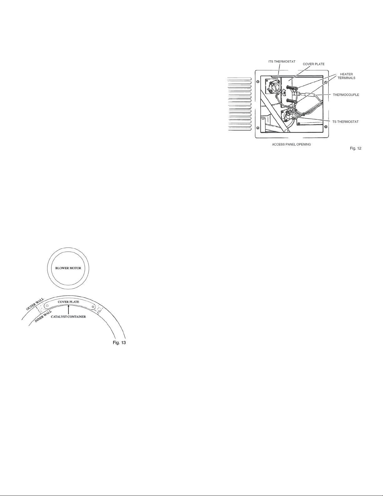
2. BLOWER THERMOSTAT (ITS) turns fan off when outside skin of chamber cools to 130°F and will turn fan
on again if temperature increases. It is accessible through access panel opening, just to the left of the heat-
er terminals. To replace, follow same procedure as for STS above. (Fig. 12)
3. LIMIT THERMOSTAT (TS) turns heater off if skin of chamber reaches a temperature of 300°F. It is located
below the ITS blower thermostat and heater terminals, outside ashpan compartment. To replace, follow
same instructions as for other thermostats. (Fig. 12)
UNDERSTANDING ELECTRICAL OPERATION
6

Always keep your INCINOLET clean to prevent odors.
• Empty ashpan daily, (or when ash is no more than 2 inches deep). EXCESSIVE ASH BUILD-UP CAUSES
ODOR, SHORTENS HEATER LIFE, AND DECREASES EFFICIENCY. If ash is caked and hard to remove, just
soak insert pan for a few minutes in warm water.
• Wipe up urine spills as they happen.
• Every 3 to 6 months – clean blower wheel and inside of INCINOLET.
1. Unplug toilet and remove top. (See instructions below.)
2. Clean inside with a detergent or a spray cleaner such as Formula 409.
(Do not use pine oil cleaners.) OR ANYTHING SCENTED
3. Remove blower wheel and clean. (See page 11.)
4. DO NOT STEAM CLEAN.
5. Stainless steel polish can be used on outside surfaces to keep INCINOLET’s finish lustrous
Top is held in place with four screws, two per side and a rubber boot which protects the start button. Remove
them, and then lift top up. To replace top: With incinerator lid closed, hold bowl halves together and lower top
into position. Replace four screws and rubber boot over start button. Tip: If you have trouble holding bowl
halves in closed position while placing it back on toilet, just use a small piece of masking tape to hold them
together, then slice through it from the top later.
Four screws hold on Access Panel, located on the right side of toilet (same side as foot pedal). Remove panel
to expose blower thermostat, limit thermostat, thermocouple, and heater terminals. (Fig. 12)
BE SURE that the top edges of the liner are below the lid when it closes. Otherwise, paper will burn outside
the chamber and cause momentary smoke and odor. CAUTION: Failure to use bowl liner for each and
every use will always cause odor and urine on the floor. Bowl liners are made of a special paper coated
with polyethylene film. This liner is necessary to catch and contain the waste, then convey it into the incineration
chamber. USE A BOWL LINER FOR EACH AND EVERY USE. Liner protects the bowl and prevents urine from
draining to the floor.
TIP: If blower becomes
noisy or vibrates, clean
or replace blower wheel.
(See page 11.)
CARE AND CLEANING
REMOVING THE TOP (SEAT, LID, BOWL HALVES)
ACCESS PANEL
BOWL LINERS
HOW TO REMOVE ASHPAN Remove ashpan only when pan is cool and toilet is not operating
7

TIMER & TEMPERATURE CONTROLLER THE KEY TO TROUBLESHOOTING
Timer limits heating cycle, Controller limits heater temperature. Timer and temperature con-
troller are within control box in upper right corner of housing, accessible with top removed.
Timer has two lights: GREEN and RED.
Temperature controller has one RED light. A steady GREEN light on timer indicates unit
has power and is ready for operation. When start button is pushed, GREEN LIGHT BEGINS
BLINKING and the RED light comes on and stays on for a timed interval, during which time
temperature controller is activated and its RED light is on. Controller RED light means that the
relay is activated and supplying power to heater. Controller RED light stays on until timer cuts
off after the timed interval, or heater reaches maximum allowed temperature and thermo-
couple signals controller to open relay. In actual operation, when timer reaches end of timed
interval, its RED light goes off, and BLINKING GREEN LIGHT TURNS STEADY again. During
the timed interval controller shows current temperature of heater coil. To see what controller
is set to, push mode key which toggles between actual and set temperatures. Setting is 1030
degrees f. for 2000- watt toilets, 996 degrees f. for 3500-watt toilets. If “FFF” shows on face
of controller, replace thermocouple. DO NOT CHANGE SETTINGS
TIMER ADJUSTMENT: (See Fig. 8.) Timer dial reads 0 to 3 hrs. Timer pointer is set to 75 minutes. If INCINOLET is used primarily
for solid deposits in rapid succession and incineration is incomplete, move pointer to 1.5-2.0 hrs. If used throughout the day, both
for urine and solids, timer would be best set at 1 to 1-1/2 hr. To adjust timer, remove top of toilet and turn dial so timer reads new
setting. (See p. 7.) Replace top. DON’T MAKE ANY ADJUSTMENT REQUIRING SCREWDRIVER.
Unplug toilet before doing repairs. Shock hazard present when toilet is plugged in for testing.
BLOWER COMES ON BUT HEATER DOESN’T HEAT Remove top, examine timer and controller as above. If both timer and control-
ler lights are on, then heater has failed. To verify, remove access panel, measure voltage directly across heater terminals, not from
terminal to ground. If voltage appears, REPLACE HEATER. If no voltage appears, check circuit further.
TIMER LIGHTS WORK BUT CONTROLLER RED LIGHT IS NOT ON Test thermocouple. Unplug toilet, remove side access panel. Re-
move wire nuts from thermocouple leads (#6 & #7). Twist the gray and purple wires together, then plug unit in and push start but-
ton. If controller red light comes on, REPLACE THERMOCOUPLE. Do not let toilet run more than 4 minutes or heater damage will occur
CIRCUIT BREAKER OPENS WHEN START BUTTON IS PUSHED This indicates heater may be shorted to ground. Unplug toilet,
remove access panel. Remove orange lead wires to heater terminals. Plug toilet in, push start button. If blower comes on and
circuit breaker does not open, heater is shorted. REPLACE HEATER. Unplug toilet, examine all wiring which might be grounded by
touching housing. REPLACE OR TAPE ANY BARE WIRES.
NOTHING COMES ON, BUT TIMER GREEN LIGHT IS ON Inspect timer lights as you push start button. Red lights should come on,
green light should begin blinking. If not REPLACE TIMER.
BLOWER, HEATER WON’T STAY ON If timer, blower and heater come on when start button is pushed but turn off as soon as
start button is released, REPLACE TIMER.
TROUBLESHOOTING
8

BLOWER STOPS AT END OF HEATING CYCLE Blower should be on from 20 to 40 minutes after heater cuts off. Unplug
toilet, remove access panel, inspect, tighten any loose wires. REPLACE BLOWER THERMOSTAT.
BLOWER DOES NOT OPERATE Blower must come on immediately when start button is pushed and should not stop while
heater is on. If not, check blower wheel to be sure it’s not binding. Listen to blower motor for a humming sound (like motor is trying
to start). This would indicate bad motor bearings. REPLACE BLOWER MOTOR.
If motor has power going to it, replace timer.
BLOWER OFF & ON AT CYCLE END Itisnormal for blowertostop for 4 or 5 minutes, then start again forafewminutes, a couple
oftimes at endof cycle. If, however, blower stops & starts rapidly, blower (ITS) thermostat is faulty. REPLACE ITS THERMOSTAT.
BOWL HANGS OPEN: PEDAL WON’T RETURN
1. Closing mechanism may be out of adjustment.
2. Foot pedal goes too far down and locks up.
Place block under foot pedal to prevent excess travel.
EXCESSIVE NOISE, VIBRATION
Clean or replace blower wheel.
INCOMPLETE INCINERATION
Can be any one of several causes:
1. Start button not pushed after each use.
2. Ashpan too full. Empty more often. (Empty when ash is no more than 2 inches deep.)
3. Too many people using toilet.
4. Burn cycle too short. Re-set timer.
ODOR WITHIN ROOM
Can be any one of several causes:
1. Failure to use bowl liner each and every time or careless use of liner.
2. Solids not completely incinerated. Run extra cycles or add time to timer.
3. Ashpan too full. Empty more often. (Empty when ash is no more than 2 inches deep.)
4. Back-drafting. Use back-draft preventer on horizontal vent-line or run
the vent vertically with a rain cap at the top.
ODOR OUTSIDE
Causes same as above, plus:
1. Catalyst port perforations are clogged. Clean chamber wall behind
heater coil with small brush.
2. Catalyst has “set”. REPLACE CATALYST. (See catalyst p. 12.)
3. Incinerator lid hanging open, allowing odor to escape.
RESIDUE BLACK, LIKE CHARCOAL
Ash should be gray. Black lumps means insufficient air is being drawn into chamber. There may also be soot around ashpan lip
at front and on inside of ashpan panel. Clean blower wheel or remove ashpan and use small brush to clean perforations in inner
incinerator wall back of heating coils.
TROUBLESHOOTING
9

For help with troubleshooting call
1-800-527-5551
or to order parts
www.incinolet.com
If service is needed, see the data plate on the back of
toilet. Please note serial # and voltage of your toilet.
10

CLEAN BLOWER WHEEL
Blower draws fresh air into toilet to provide oxygen for the burn, carries smoke
and odor into the catalyst, then exhausts moist air outside. Clean blower wheel
and housing every 3 - 6 months, or any time excessive noise and vibration occur.
1. Unplug Incinolet and remove the top.
2. Disconnect two wires on side of control box to free motor.
3. Loosen (no need to remove) 3 screws holding blower motor plate. (Fig. 10)
Twist and lift motor over screw slots to remove it.
4. Use 1/8” Allen wrench to remove set screw in wheel hub.
5. Clean grease and dirt from wheel with hot soapy water or a degreasing cleaner.
6. Replace wheel if corroded or if vibration indicates it is out of balance.
7. Clean inside of blower housing occasionally.
8. You can also clean the wheel without removing it.
DO NOT GET BLOWER MOTOR WET
MAINTENANCE AND REPAIRS
Unplug INCINOLET
REPLACE HEATER
Note: For maximum heater life incinerate after each use, and keep ash level down to no more than 2 inches
TO INSTALL NEW HEATER:
• Reverse above procedure. Locate heater in brackets, making sure brackets are seated in slots in the incinerator
wall. (Fig. 11-2) IMPORTANT: Locate heater at lowest position in heater bracket. Coils must not touch each other.
• Replace insulation and cover over heater terminals. (Fig. 11-1)
• New heater coils are furnished with a hex nut, already firmly tightened against the mica insulation, washers,
and a lock nut or 2 nuts. Attach wire terminals (on the orange wires) to heater studs in this order: one washer
against the stationery hex nut, wire terminal, one washer, 2 nuts. Use a 3/8” nut driver or end wrench to tight-
en the 2 nuts against the washer. Hold the orange wire in one hand while tightening the 2 nuts, with the other
hand. Continue tightening until the orange wire terminal is quite secure and cannot be turned.
• Replace thermocouple. Push knurled cylinder to compress spring. Turn to engage stud, then release. Spring
must be compressed to insure that tip of thermocouple contacts outer surface of heater. (See p. 12.)
• Replace access panel, ashpan, top. Close circuit breaker.
• Plug INCINOLET in. Start cycle to test heater and total operation.
Unplug INCINOLET.
TO REMOVE OLD HEATER:
Remove ashpan. Remove access panel. Remove top. Hold incinerator open either by
wedging down the foot pedal or blocking flushing mechanism in open position.
• Remove thermocouple but do not disconnect. (Fig. 12)
• Disconnect wiring to heater terminals. Remove cover
plate and insulation around heater terminals. (Fig. 11-1)
• Push up on heater coils to clear
heater brackets. (Fig. 11-2)
• Remove heater through ashpan opening. (Fig. 11-3)
Note: Brackets may be wedged tightly in slots in wall.
It is okay to remove brackets, but not absolutely necessary.
11

12
THERMOCOUPLE
Thermocouple, in combination with the temperature controller, limits
temperature of the heater and prevents overheating. Thermocouple,
Type K, develops a small voltage proportional to the temperature of the
heater. Thermocouple is located to the right of and midway between
heater terminals. (Fig. 12) Tip of thermocouple makes contact with the
lower heater coil. Thermocouple leads are color-coded. Wire with red
core must be connected to purple lead #7 within the “F” wire nut. Wire
with yellow core must be connected to gray lead #6 in “E” wire nut.
CATALYST INCINOLET uses a heat-activated, platinum type catalyst pellets to suppress
smoke and odor. Pellets are contained in a chamber within the incinerator walls
near the blower, and do not normally need to be replaced. Inner and outer walls
of the chamber are perforated to allow the blower to draw odor through catalyst
pellets. A crescent shaped cover is held on with two small nuts.
In time, pellets may become too closely packed to allow proper flow of odor
through the catalyst. Dust and ash may clog the chamber perforations, forcing
smoke and odor out through the front of the ashpan, through the blower, and on
to the outside.
If exterior odor is bad and inside of toilet is clean, replace catalyst.
1. To replace thermocouple, unplug INCINOLET and remove side access panel. Disconnect wire leads with “E” and
“F” wire nuts. Then push in knurled rod, turn to disengage, pull out thermocouple.
2. To install new thermocouple, reverse procedure. Make sure that wire with red core is connected to purple #7 and
yellow core wire is connected to gray #6.
3. After inserting thermocouple, be sure that the tip is making contact with lower heater coil along outer surface of coil.
IMPORTANT: EXACT PROCEDURE MUST BE FOLLOWED
TO PREVENT OVERHEATING AND HEATER FAILURE:
REPLACE RELAY
Relay acts as a switch that controls electric current to the heater within the time constraints of the Timer and the
temperature constraints of the Controller. Relay is located in the control box beside the timer and controller.
1. Unplug INCINOLET and take the top off.
2. Remove six lead wires to relay terminals. Carefully mark so you can reattach in the proper positions.
3. Hold back spring clips that hold relay in place.
4. Pry relay out. Replace and rewire.
SAFETY FEATURES
1. Timer limits heating cycle.
2. Temperature Controller limits heater temperature.
3. Safety Thermostat (STS) prevents overheating if blower were to fail.
4. Limit Thermostat (TS) limits temperature if controller were to fail.
MAINTENANCE AND REPAIRS Continued

PARTS LIST
PART 240 VOLT UNITS 120 VOLT UNITS
ASHPAN, Composite, SS
ASHPAN INSERT, SS
BLOWER HOUSING, SS
BLOWER MOTOR
BLOWER WHEEL
BRACKET SET, for heater
CATALYST, 1/4# BAG
CONTROLLER, Temp., Omron
HEATER - (120v)
(240v)
RELAY, Omron
SEAT&LID
SPRING, 1/4” diameter x 4” long
THERMOSTAT, TS -L-300
THERMOSTAT, ITS -F-130
THERMOSTAT, STS-L-140
THERMOCOUPLE
TIMER, Omron
PAN023
PAN027
HOU004
MOT010
WHE002
BRA009
CAT003
CON018A
HEA007
REL008
SEA00l
SPR 003
THE012
THE014
THE013
THE009
TIM016
PAN023
PAN027
HOU004
MOT006
WHE002
BRA009
CAT003
CON018A
HEA044
REL007
SEA001
SPR 003
THE012
THE014
THE013
THE009
TIM016
WIRING INSTRUCTIONS This unit is furnished with an electric cord and plug. It requires a circuit protected with a 20 amp
circuit breaker and no other appliance on it. DO NOT CONNECT TO POWER BEFORE VENTLINE HAS BEEN INSTALLED.
WIRING DIAGRAM:
WIRE COLORS: Black=B
Red=R Blue=BL Orange=O
Gray=G Purple=P Tan=T
White=W Brown=BR Yellow=Y
Thermocouple Lead 6 is ( +)
Thermocouple Lead 7 is (-)
NOTE: UNIT IS GROUNDED INTERNALLY THROUGH THE FURNISHED CORD
AND PLUG. MAKE CERTAIN THAT YOUR CIRCUIT HAS ADEQUATE GROUNDING.
A, B, C, D, E, F & G ARE WIRE NUTS:
A connects BL3, R7, B3, R2, T1
B connects Bl, BL3, 02
C connects Wl, W3, W10
D connects BL9, BL9
CONTROL ELEMENTS:
ITS - Inverse thermostat to control blower - F-130
STS - Safety thermostat in case of blower failure - L-140
TS -Limit thermostat to prevent overheating- L-300
SW - Start Switch
E connects G6, Y
F connects P7, R
G connects W3, W4, W,8
208v Units use 240v parts except: 208v heater HEA009 and 120v Blower Motor MOT006
S/N 4100 and UP
Please provide your serial # with your parts order
S/N 57200 and UP
TOLL FREE
1-800-527-5551
Research Products/Blankenship
2639 Andjon Drive I Dallas, Texas 75220
(214) 358-4238 I Fax (214) 350-7919
www.incinolet.com
Unplug before performing any electrical repairs
13
This manual suits for next models
1
Table of contents
Other INCINOLET Toilet manuals