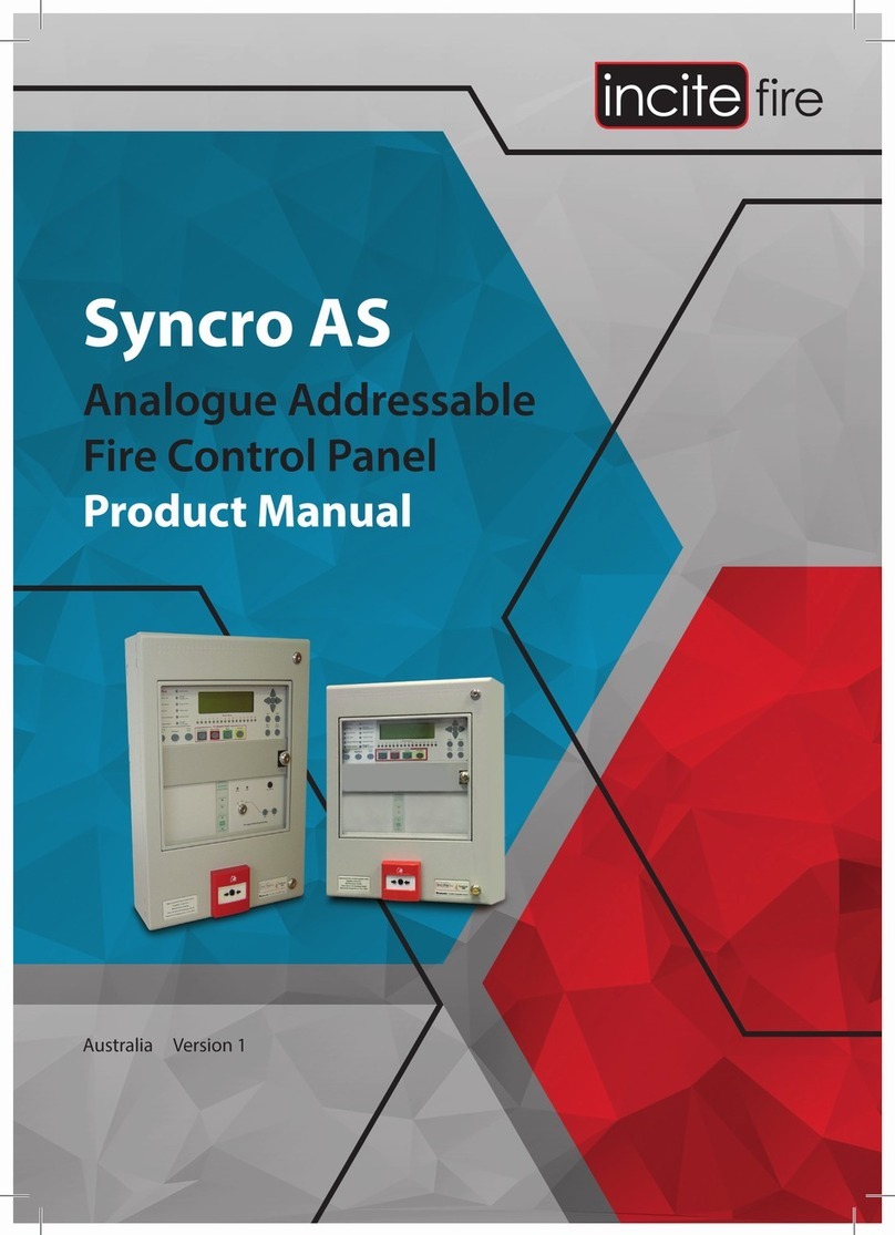
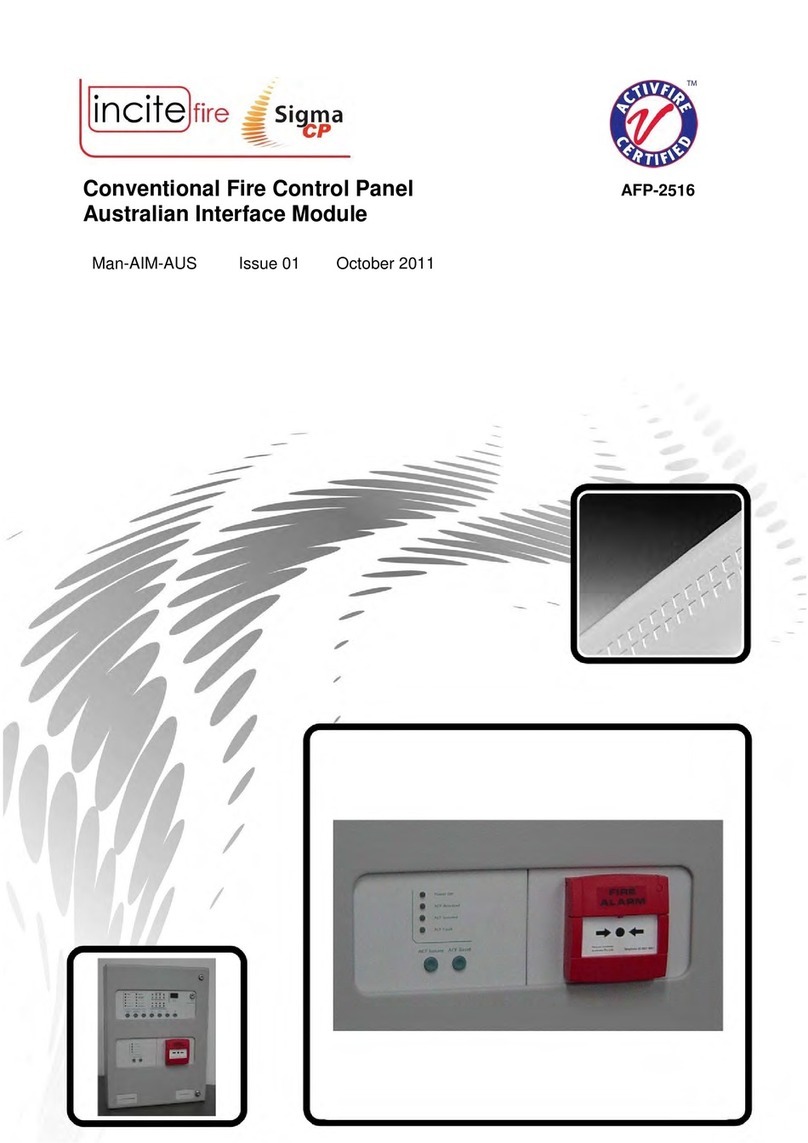
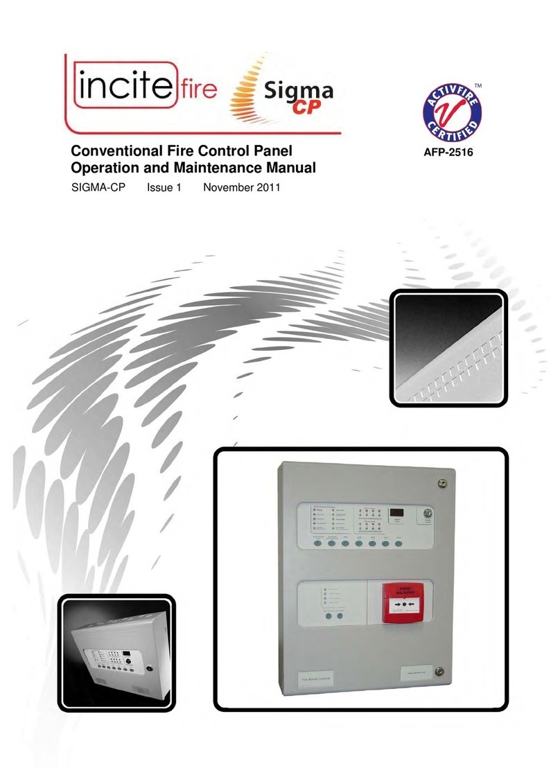
Incite Fire Sigma CP User manual

Quick Reference Guide
Conventional
Fire Control Panel
Sigma CP
Australia Version 1

How To
Do This
Display
Comments
Silence buzzer
Alarm/Fault
Buzzer Silenced
Press button
Buzzer will resound on next
event.
Test lamps
Lamp
Test
Press button
All lamps on
Buzzer sounds whilst button
is pressed
Enable buttons
Enable Control
Turn key
W
Buzzer beeps twice every
few seconds
Silence alarms
Silence/Sound
Alarm
Press button
Alarm/Fault
Buzzer Silenced
Sound alarms
Silence/Sound
Alarm
Press button
Buzzer pulses
rapidly
Reset
Reset
Press button
Ensure source of fire event is
cleared before resetting.
Disable a zone
Step 1
Mode
Press button until d1 is
displayed
'
First display
Disable a zone
Step
2
Select
Press button to scroll
zones
'
Zone 5
Zone 5 for example
Disable a zone
Step 3
Enter
Press button
5 6 7
Zone Fault
Fire in Zone
Zone 5 fault LED is lit
General
Disablement
G
Dot flashes to indicate
disablement
Fire
Alarm/Fault
Buzzer Silenced

How To
Do This
Display
Comments
Put a zone into test
mode.
Step 1
Mode
Press button until t1 is
displayed
W
First display
Put a zone into test
mode.
Step 2
Select
Press button to scroll
zones
W
Zone 5
Zone 5 for example
Put a zone into test
mode.
Step 3
Enter
Press button
5 6 7
Zone Fault
Fire in Zone
Zone 5 fault LED is lit
General
Disablement
W
Dot flashes to indicate test
mode.
Enable a zone
Step 1
Mode
Press button until d1 is
displayed
'
First display
Enable a zone
Step 2
Select
Press button to
scroll
zones
G
Zone 5
Enable a zone Step 3
Enter
Press button
5 6 7
Zone Fault
Fire in Zone
Zone 5 LED extinguishes
General
Disablement
General disablement
indicator extinguishes
Disable sounders
Step 1
Mode
Press button until db is
displayed
GE
Disable sounders
Step 2
Enter
Press button
GE
Dot flashes to indicate
bells/sounders are disabled.
General
disablement and
sounder Fault/Disablement
indicators lit.

How To
Do This
Display
Comments
Enable sounders
Step 1
Mode
Press button until db is
displayed
GE
Enable sounders
Step 2
Enter
Press button
GE
Dot extinguishes to indicate
bells/sounders are enabled.
General disablement and
sounder Fault/Disablement
indicators extinguish.
Activate zone input
delays
Step 1
Mode
Press button
until Ad is
displayed
$G
Activate zone input
delays
Step 2
Enter
Press button
$G
Dot flashes to indicate that
delays are active if they have
been set in engineering
mode. (refer to operation
and maintenance manual)
Deactivate zone
input delays
Step 2
Mode
Press button until Ad is
displayed
$G
Dot flashes to indicate that
delays are active if they have
been set in engineering
mode. (refer to
operation
and maintenance manual)
Activate zone input
delays
Step 1
Enter
Press button
$G
Dot stops flashing to indicate
delays have been
deactivated
Return system to
normal
Enable Control
Turn key
Leaves only Alarm/Fault
Warning Silence and Lamp
Test buttons operable
For service contract:
Telephone:

Notes to Technicians and Testers.
This incite Sigma and Syncro range of panels have been designed to meet AS7240.2 and AS7240.4
These standards are very different in both their panel operation and operating parameters from the old
Australian standards, AS4428.1 and AS1603.4.
The main differences are outlined here as follows;
Access Levels: AS7240 allows for 4 different access levels as follows:
1. Public Access Level: This level is always active
a. Silence the panel buzzer
b. Perform a lamp test
2. Operator Access Level: This level is entered by turning a key or by entering a code. This is the
level accessible to the Fire Brigade.
a. All the above plus
b. Sound Alarm Devices, e.g. Activate and Evacuation signal
c. Silence Alarm Devices
d. Reset the panel
e. Activate Delays
f. Set Test mode
g. Disable circuits
3. Technician Access Level: This level is entered by entering a code which is different from that used
for Access Level 2, or setting a switch which is not normally available to an Operator, e.g behind a
locked door.
a. All of the above plus
b. Changes to the configuration, e.g set delay times, add devices/modules to the panel.
4. Engineering Access Level: This level is entered via a laptop or other device using specialised
software to upgrade or change the firmware within the panel. This level is only available to the
manufacturer and authorised technicians
Disablement: This is not an isolate! An isolate allowed the circuit to be monitored and indicate its condition
without causing activation. A disablement, depending on the design, may or may not allow a circuit to be
powered but will not indicate the state of the circuit. The circuit is disabled.
The standard list a disablement as: “Disablements shall inhibit all corresponding mandatory indications or
outputs or both, but shall not prevent other mandatory indications and/or outputs.”
Care must be taken when enabling a disabled circuit to ensure that it is not active.
It is good practice to perform a reset on any disabled detection circuit before enabling it.

Alarm and Fault Test: Under AS7240, neither alarm test or fault test exists. During maintenance, an
installation is required to be tested by activating a detector on that circuit and ensuring that the panel and
outputs operate successfully due to that activation. In this way, the integrity of the entire system is ensured.
Test: This is similar to a Walk Test, where the detector will activate and then reset approximately 5 seconds
later, but the outputs will activate indicating that the entire system is working. Any outputs which must be
maintained during a test, such as computer shutdown, will need to be disabled prior to performing any test.
Power Supplies: Under AS7240, the power supply must be capable of powering the panel, ALL alarm
loads AND charge the batteries. In other words, the panel must be able to operate in all modes without any
batteries connected.
Alarm Delays: AS7240 allows for alarm delays on sounders and outputs. The majority of panels in Australia
will not use this function, but they are included here for completeness. These are configured at Access Level
3, but activated at Access Level 2. Delays under AS7240 can be up to 10 minutes in length.
When the delay is activated and an alarm occurs, the output will not operate until this delay period has
expired.
Refer to the Sigma CP Operation and Maintenance Manual, Table 8 for configuration options.
Earth Fault: An AS7240 panel will detect if there is an earth fault on the system
Alarm Verification: AS7240 does not have alarm verification
Sounders, Bells and Warning System: AS7240 does not discriminate between sounders, bells and a warning
system. They are all sounders. Controls are provided to silence and re-sound sounders at access level 2.
Fire Fighters Facility: AS7240 does not have a Fire Fighters Facility.


Sydney
Block Y, Unit 1, 391 Park Road, REGENTS PARK NSW 2143
Mail: PO Box 508 GYMEA NSW 2227
Phone: 1300 INCITE (1300 462 483) | 02 9644 7144
Fax: 02 9644 7255
Email: sales@incitere.com.au
Technical support: support@incitere.com.au
Melbourne
Address: Unit 120, 45 Gilby Road, MT WAVERLEY VIC 3149
Phone: 03 9544 2211
Fax: 03 9544 2212
Email: salesvic@incitere.com.au
Brisbane
Address: 25 Jeays Street, BOWEN HILLS QLD 4006
Phone: 07 3252 5366
Fax: 07 3252 4099
Email: salesqld@incitere.com.au
Perth
Address: 19 Halley Road, BALCATTA WA 6021
Phone: 08 9349 2972
Email: saleswa@incitere.com.au
Other manuals for Sigma CP
1
Other Incite Fire Control Panel manuals
Popular Control Panel manuals by other brands

Bender
Bender COMTRAXX CP9 Series quick start guide

American Standard
American Standard NEXIA ACONT624AS42DA user guide
BFT
BFT LEO B CBB 3 230 L02 installation manual
See Water
See Water OSSIM-TP-100 Series Installation and operation manual
Frigidaire
Frigidaire FES365EBE Control function
Biamp
Biamp Apprimo Touch 8i Installation and operation guide
