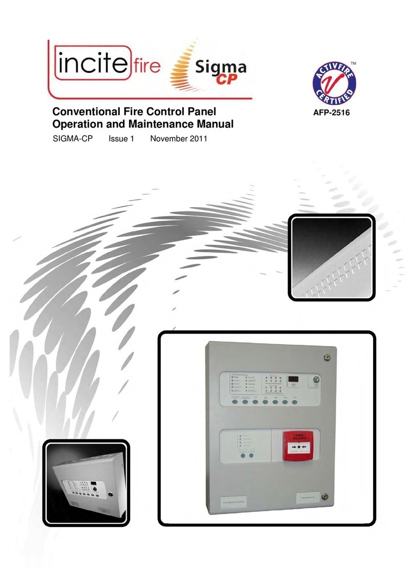
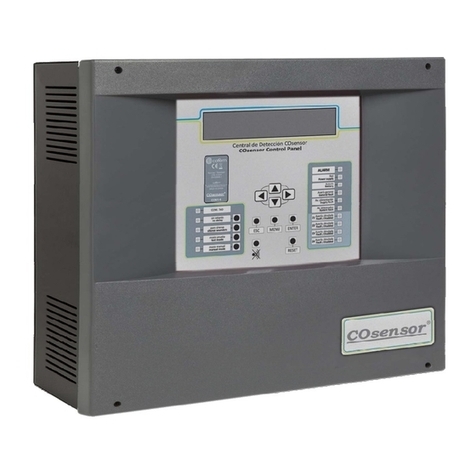
Incite Fire Sigma CP AFP-2516 User manual

Man-AIM-AUS Issue 01 October 2011
Conventional Fire Control Panel AFP-2516
Australian Interface Module

Sigma_CP_Australian Interface Module.doc Page 2 of 9
Index
Section Page
1 Introduction ................................................................................................ 3
2 Safety and mounting .................................................................................... 4
2.1 Safety ..................................................................................................................... 4
2.2 Mounting ................................................................................................................. 4
3 Technical specification .................................................................................. 5
4 Connecting to the circuit board ...................................................................... 5
5 24V Input ...................................................................................................
Connection to main panel and other boards.....................................................
7 Operation ................................................................................................... 8
7.1 Normal condition ...................................................................................................... 8
7.2 ACF – Ancillary Control Facility .................................................................................. 8
7.2.1 Outputs.............................................................................................................................8
7.2.2 Configuration:..................................................................................................................8
7.2.3 Controls – only available at Access Level 2....................................................................8
7.3 Door older Output .................................................................................................. 8
7.4 ASE Outputs (Alarm Signalling Equipment) ................................................................. 9
7.5 Fuse fail .................................................................................................................. 9
7.6 COMMS ................................................................................................................... 9
7.7 Microprocessor Reset link .......................................................................................... 9
7.8 Module Address ........................................................................................................ 9
8 Power requirements ..................................................................................... 9

Sigma_CP_Australian Interface Module.doc Page 3 of 9
1Introduction
The Sigma CP Australian Interface Module is optional on the Sigma range of panels and can be
utilised to provide a means of connecting to an Ancillary Control Facility (ACF), magnetic door
holders, and Alarm Signalling Interface (ASE) from the control panel via a 2 core data bus.
The Australian Interface Module is compatible with all Sigma CP control panels.
Only one AIM is permitted on each control panel and has a fixed addressed at “o7”, output unit 7.
NOTE: The Australian Interface Module, if fitted, is fixed at address 7, and in this instance only 6
Ancillary boards can be fitted at addresses 1 to 6.
The total length of the data cable from the main panel must not exceed 1200 metres.
Australian Interface Module Overview

Sigma_CP_Australian Interface Module.doc Page 4 of 9
2Safety and mounting
2.1 Safety
Suppliers of articles for use at work are required to ensure as reasonably as is practical that the
article will be safe and without risk to health when properly used.
An article is not regarded as properly used if it is used ‘without regard to any relevant information
or advice’ relating to its use made available by the supplier.
This product should be installed, commissioned and maintained by trained service personnel in
accordance with the following:
(i) Local regulations for electrical equipment in buildings
(ii) Codes of practice
(iii) Statutory requirements
(iv) Any instructions specifically advised by the manufacturer
You are therefore requested to take such steps as are necessary to ensure that you make any
appropriate information about this product available to anyone concerned with its use.
This Ancillary board is designed for indoor use only and at temperatures between -50C and +400C
and with a maximum relative humidity of 95%.
The IP rating for the enclosure is IP30.
Operation outside of these limits may render the equipment unreliable and unsafe.
2.2 Mounting
If not fitted inside a Sigma CP panel, the board should be mounted in a suitable enclosure such
that it is protected from ingress of water, dust or foreign bodies.
It should be positioned in an accessible place as agreed with the end user.
Suitable fixings should be used at all fixing points such that the board and enclosure are securely
mounted and not liable to move once fixed.
The enclosure should not be mounted near sources of excessive heat.
Cables should be connected using suitable, metal, shielded cable glands. All swarf and debris
caused by drilling of additional cable entries must be cleared before power is applied.

Sigma_CP_Australian Interface Module.doc Page 5 of 9
3Technical specification
Table 1 – Electrical Specifications
Power supply 21 to 30 V DC Nominal 24V DC
Maximum ripple current 200 millivolts
Maximum current draw 0.25 Amps In full alarm
Mains failed current consumption 20 milliamps In standby mode
Zonal relay contact rating 30VDC 1A Amp maximum for each Maximum ratings not to be exceeded
Fault relay contact rating 30VDC 1A Amp maximum for each Maximum ratings not to be exceeded
Fire relay contact rating 30VDC 1A Amp maximum for each Maximum ratings not to be exceeded
Coincidence relay contact rating 30VDC 1A Amp maximum for each Maximum ratings not to be exceeded
Terminal capacity 0.5mm
2
to 2.5mm
2
solid or stranded wire
Cabling - power FP200 or equivalent Metal cable glands should be used
Cabling - communication RS485 data cable or FP200 Maximum total cable distance 1200
metres. Metal cable glands should be
used
Size 155 X 135 X 30 Millimetres
Fixing Four 4mm holes One in each corner of the board
4Connecting to the circuit board
All connections for field wiring are to rows of terminals along the top and bottom of the circuit
board.
Cabling must comply with the relevant Australian Standards. Shielded fire alarm cable for power
and RS485 data cable for comms and metal cable glands should be used for all connections to the
board. The resistance of any core of any cable must not exceed 25 ohms. The shields of the
cables should be bonded securely to the enclosure via metal glands.
Wiring should enter the enclosure and be formed tidily to the appropriate terminals which are
capable of accepting wires of up to 2.5mm2.
Wiring must not go across the front of the circuit board. If cable entries need to be in positions
other than at the knockouts provided, wiring must be fed well away from the surface of the circuit
board.
Figure 1- Wiring to the circuit board
CORRECT
INCORRECT INCORRECT

Sigma_CP_Australian Interface Module.doc Page 6 of 9
Figure 2-Power connection
524V Input
The Australian Interface Module requires a nominal
24V DC power supply to operate. This can be taken
from the AUX 24V output of the panel to which the
ancillary board is connected or another 24V DC source
if this is more convenient.
Four power terminals are provided so that 24V DC
wiring can be taken into the module and then out again
on to other ancillary boards or other equipment.
6Connection to main panel and other boards
If power is supplied locally to the Australian Interface Module board only two wires are required
from the main panel.
Wiring can be standard fire alarm cable or shielded data cable. The shield of the cable must be
securely bonded to the enclosure case at both ends, and must comply with the relevant Australian
Standards.

Sigma_CP_Australian Interface Module.doc Page 7 of 9
To terminate the data cable correctly,
the last board on the comms line must
have jumper J2 fitted as shown.
For the position of J2 on other panels or
boards refer to the relevant manual.
After the AIM has been connected to
the main panel, the main panel has to
“learn” that it exists. This is necessary
so that the main panel can announce a
fault condition if the AIM becomes
disconnected.
To “teach” the main panel that an AIM is
connected, ensure that all other boards
have the data cable connected with the
correct polarity. Check that all boards
are supplied with power and that the
green, OK LED is lit at each one.
Press the processor reset switch on the
main panel PCB. The main panel will
display the address of the first board it
finds on the seven segment LED display
such as.
o1
This indicates ancillary board 1 (o1). To accept this, the enter button on the main panel should be
pressed whereupon, if more boards are found, their addresses will be displayed and must be
accepted by pressing the enter button once again. This is repeated until all of the boards are
recognised by the main panel. The AIM is fixed at ancillary board address 7 and will appear on the
display as
o7
If any board becomes disconnected after it has been “learnt” by the main panel, the main panel will
display a comms fault and the number of the board will be shown on the seven segment LED
display.
The board/s that have become disconnected from the main panel will also display a comms fault
on their COMMS LED.
Figure 4-Comms terminating jumper on the AIM

Sigma_CP_Australian Interface Module.doc Page of 9
Operation
7.1 Normal condition
Under normal conditions, ancillary boards will have only the green, OK LED lit.
7.2 ACF – Ancillary Control Facility
7.2.1 Outputs
The ACF has a 24V DC monitored output suitable for operating a remote, polarised and suppressed
relay. Monitoring is via an end of line resistor. This output is designated ACF O/P +/-
A clean contact relay rated at 30VDC 1Amp follows the monitored output.
The ACF outputs are activated by a non-silenceable fire signal from the Sigma control panel
section. A red LED indicator is lit when the output is active.
A fault on the ACF outputs is signalled at the Sigma panels as a General fault and on the AIM as
ACF fault.
7.2.2 Configuration:
The ACF can be configured as latching by setting the LATCH dipswitch to the ON position.
The ACF can be configured as failsafe (Normally Energised) by setting the FAIL S. dipswitch
to the ON position.
7.2.3 Controls – only available at Access Level 2
When the ACF is set to “latching” the Reset switch on the AIM module, in order to reset the ACF,
firstly, the Alarm must be reset, and then the ACF can be reset using the ACF Reset switch on the
AIM module.
When the ACF is set to “non-latching”, the ACF output is deactivated when the alarm is reset or
disabled.
The Isolate switch on the AIM module allows the ACF output to be disabled and not operate on an
alarm condition. A yellow ACF Isolated LED indicates when the ACF is isolated, and signals a
General Disablement to the Sigma control panel section.
7.3 Door Holder Out ut
The door holder circuit allows magnetic fire doors to be automatically closed in the event of a fire,
thus limiting smoke and fire egress in an emergency situation.
Four terminals are provided:
D 24V In A 24V supply to power the magnetic door holders.
Door olders The 24V from the “D 24V In” circuit appears at this output under
“Normal” condition. When an alarm occurs, power is disconnected from the “Door older” output.
The maximum output of the Door older circuit must be less than 1A.
The status of the door holder output follows that of the ACF output as described in section 7.1 and
is isolated via the ACF Isolate facility. The only exception is when the DOOR D. dipswitch is ON,
the Door older Output activates after a 30 seconds delay.

Sigma_CP_Australian Interface Module.doc Page 9 of 9
7.4 ASE Out uts (Alarm Signalling Equi ment)
Volt free relay outputs, rated at 30VDC 1Amp, are provided to facilitate connection of the Sigma
fire panel to a variety of ASE depending on the installation. These contacts are rated for switching
signalling circuits only and the maximum ratings listed in Error! Reference source not found. on
page 5 should not be exceeded under any circumstances. It is the responsibility of the installer to
ensure that the ASE being installed is compatible with the local fire station to which it is being
connected.
ALARM normally de-energised, activates on a non-disabled Alarm
FAULT normally de-energised, activates on a non-disabled Fault
ISOLATED normally de-energised, activates on a non-disabled Disable
POWER FLT normally energised, de-activates when there is an abnormality with the power
supply.
COINC. normally de-energised, activates on multiple alarms. This output will activate when
an alarm occurs any of the zones specified as being coincident zones. See options
51 to 58 in Sigma CP Fire Control Manual.
ENABLE normally de-energised, activates when the fire panel enters the Level 2 state.
ACF O/P this output follows the state of the ACF monitored output.
If voltages or currents exceeding those in Table 1 on Page 5 need to be switched then a suitable
relay or contactor device should be interposed between the ancillary board and the system to be
controlled.
7.5 Fuse fail
The AIM is fitted with a 1 Amp rated, self-resetting electronic fuse. This fuse protects the
electronics of the AIM and prevents any excessive loading of the power supply that is powering it.
If this fuse operates, the yellow Fuse LED will light.
7.6 COMMS
If the AIM loses communication with the control panel to which it is connected, the COMMS LED
will light.
7.7 Micro rocessor Reset link
Once started, the microprocessor controlling the panel should continue to run the AIM continuously
without interruption. If the microprocessor fails to run correctly it can be reset by momentarily
shorting J3 on the rear of the PCB.
This should not normally be necessary but should be done as a matter of course if the system is
behaving abnormally. The system should resume normal operation within a couple of seconds.
7.8 Module Address
NOTE: The AIM is fixed at ancillary board address 7 and in this instance only 6 Ancillary boards
can be fitted at addresses 1 to 6.
8Power requirements
The AIM requires a 24V DC power supply which connects to the terminal block labelled 24V DC.
The power supply should be capable of supplying a minimum of 250 milliamps to cater for a fully
loaded board with all outputs activated.

Sigma_CP_Australian Interface Module.doc Page 10 of 10
When supplied from the Sigma CP panel extra battery capacity of 0.6Ah should be allowed to give
24 Hour standby.
Table of contents
Other Incite Fire Control Panel manuals
