Incite Fire FIREscape User manual

Emergency Lighting System
INSTALLATION MANUAL


FIREscape System Installation Manual
Page 5 of 56
Contents
1Introduction..................................................................................................................................7
2Overview.......................................................................................................................................8
3Standards.....................................................................................................................................8
3.1 Cables and Cable Screen.....................................................................................................8
3.2 InstallationEnvironment........................................................................................................9
4Panel Housing..............................................................................................................................9
4.1 Installation.............................................................................................................................9
5EL-KP Keypad............................................................................................................................11
5.1 Overview.............................................................................................................................11
6Installation..................................................................................................................................13
6.1 Connection..........................................................................................................................14
7Settings.......................................................................................................................................15
7.1 Start ....................................................................................................................................16
8EL-2 Connections ......................................................................................................................17
8.1 Control PanelFuses: ..........................................................................................................17
8.2 Relay Outputs.....................................................................................................................18
8.3 LEDs...................................................................................................................................18
8.4 Settings...............................................................................................................................19
8.5 Language Selection............................................................................................................19
4.8 FactoryReset......................................................................................................................19
9RS-232 Connectors ...................................................................................................................20
9.1 PC Interface, PRG..............................................................................................................20
9.2 EL-ISOL (RS-232Isolator)..................................................................................................20
9.3 EL-ISOL Connection:..........................................................................................................21
9.4 Additional Port, PRN...........................................................................................................21
10 Addressable Emergency Lighting Lines.................................................................................22
10.1 Principle..............................................................................................................................22
10.2 Mounting Base(EL-TSB)....................................................................................................22
10.3 Emergency Lighting LineConnection .................................................................................23
11 Wiring to House Lighting via PM .............................................................................................25
12 Emergency Luminaires.............................................................................................................27
12.1 EL-DL2-AS Escape Corridor Down Light............................................................................27
12.1.1EL-DL2-AS Technical Specifications........................................................................27
12.1.2EL-DL2-AS Classifications & Mounting Heights.......................................................27
12.2 EL-DL3-AS Open Area DownLight ....................................................................................28
12.2.1EL-DL3-AS Technical Specifications........................................................................28
12.2.2EL-DL3-AS Classifications & Mounting Heights.......................................................28
12.3 16 m Exit Sign.....................................................................................................................29
12.3.116 m Exit SignLenses ..............................................................................................30
12.3.216 m Exit Sign Technical Specifications...................................................................30
12.4 24 m Exit Sign.....................................................................................................................31
12.4.124m Exit Sign Lenses...............................................................................................32

FIREscape System Installation Manual
Page 6 of 56
12.4.224m Exit Sign TechnicalSpecifications....................................................................32
12.5 NF89-O-AS High Powered Emergency Escape Open Area Down Light...........................33
12.5.1NF89-O-AS TechnicalSpecifications .......................................................................33
12.5.2NF89-O-AS Classifications & Mounting Heights......................................................33
12.6 NF89-C-AS High Powered Emergency Corridor Escape DownLight................................34
12.6.1NF89-C-AS TechnicalSpecifications........................................................................34
12.6.2NF89-C-AS Classifications & Mounting Heights ......................................................34
12.7 EL-SL Step Light ................................................................................................................35
12.7.1EL-SL TechnicalSpecifications ................................................................................35
13 EL-IO Module .............................................................................................................................36
13.1 Address Switches...............................................................................................................36
13.1.1EL-IO TechnicalSpecifications.................................................................................37
14 EL-EXP Expansion Unit.............................................................................................................38
15 TCH-B200 Address Programming Device...............................................................................40
15.1 ButtonFunctions.................................................................................................................40
15.2 Programming......................................................................................................................40
16 Cabling Length ..........................................................................................................................41
16.1 IlluminationPoints...............................................................................................................41
16.2 Using the Cabling RecommendationsGraphs....................................................................41
16.3 Illumination Points at Regular Intervals..............................................................................43
16.4 Examples............................................................................................................................43
16.5 Other Devices.....................................................................................................................46
16.6 Devices at Equal Intervals..................................................................................................48
16.7 Devices at the End of The Cable........................................................................................51
17 EL-2 Technical Specifications..................................................................................................54
17.1 Control Panel ......................................................................................................................54
18 System Components.................................................................................................................55
18.1 Luminous Intensity for Exit Signs .......................................................................................55
19 Troubleshooting ........................................................................................................................57
19.1 RS-485 DataConnection....................................................................................................57
19.2 Ground Leakage .................................................................................................................57
19.2.1Interference with Keypad Data Line..........................................................................57
19.3 Luminaire Line ....................................................................................................................57
19.3.1SupplyCurrent..........................................................................................................57
19.3.2Line Data Communication ........................................................................................57
19.3.3Double Address Detection........................................................................................58

FIREscape System Installation Manual
Page 7 of 56
1 Introduction
FIREscape is an addressable intelligent emergency lighting single point system that utilizes LED technology
and low voltage SHEILDED cabling. The system is fully monitored and is controlled using up to 8 keypads (EL-
KP) per system and / or PC interface
The system monitors every mains lighting circuit by use of a phase monitor. This device triggers the initial signal
of 240v power loss to a mains lighting circuit via its communications line interfaced to the EL2 emergency
lighting control panel.
The EL2 control panel is powered by a Mains Transformer (EL 35V) that takes the 240v input from the mains
supply and converts it to 35V 220VA
Each EL2 panel runs 2 x 40v digital communications lines with each line having a capacity of up to 127 devices
or 254 per panel which can consist of a mixture of Emergency exit lights, exit signs and I/O modules. (max and
min line population is ascertained by use of a line calculator)
All luminaires are intelligent and given an address on the system to be easily identified. This address consists of
a line number and a device number.
The Hochiki FIREscape range includes 16 meter to 24-meter range of emergency exit signs with the ability to
be either wall or ceiling mounted, single sided or double sided.
The emergency escape luminaires also come in various transverse C0 and longitudinal C90 planes to best suit
building specific applications including a high powered option. All emergency escape luminaires and exits signs
are intelligent and equipped with an integral battery which once fully charged will allow the luminaire/sign to
operate for a minimum of 3 hours under a mains power failure.
All luminaires and signs fit onto a Hochiki EL-TSB magnetic test switch base for easy installation and local
operation.
The Hochiki FIREscape emergency lighting and exit system has an automatic testing facility performed weekly
in accordance with AS2293 and a manual test facility that continuously monitors battery and luminaire
performance that can be controlled through the systems keypad
The Hochiki FIREscape emergency lighting system has the ability to interface to third party products and
available with a graphics package
FIREscape System Installation Manual
Page 8 of 56
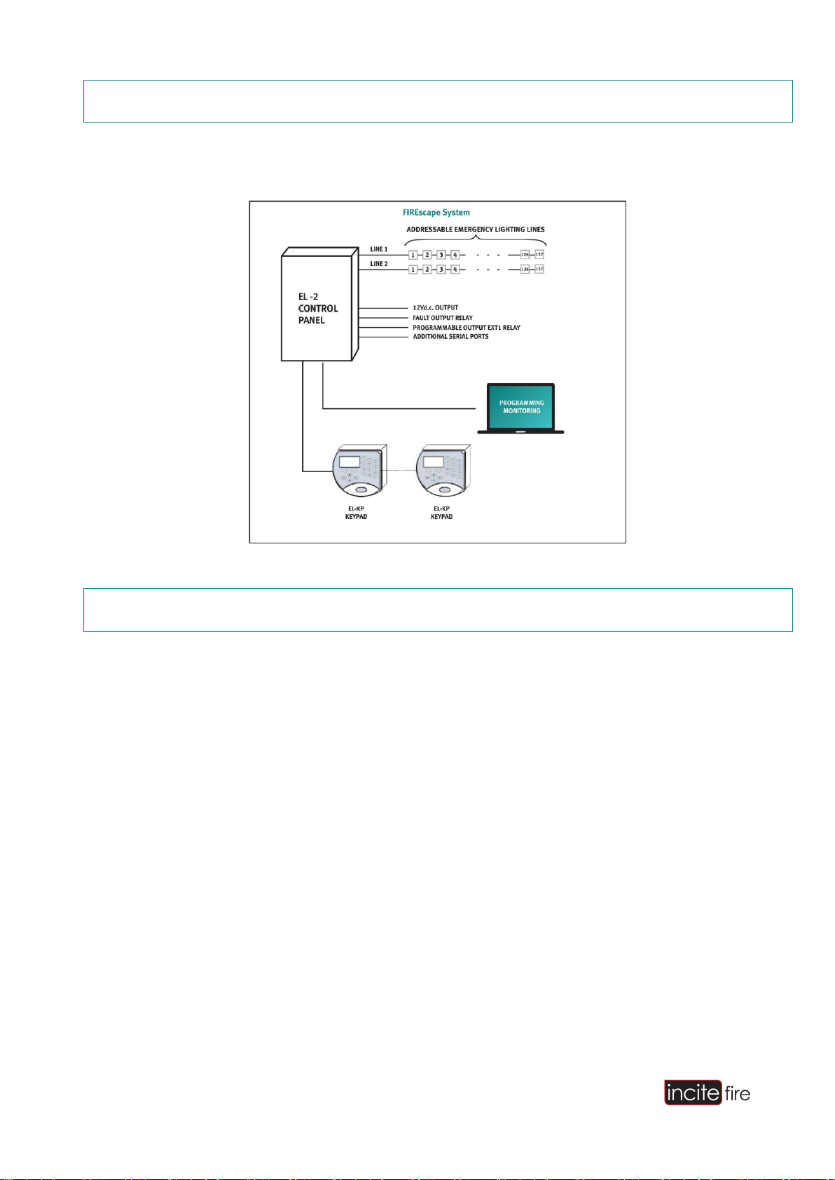
2 Overview
This guide covers the installation of the FIREscape system featuring the EL-2 Emergency
Lighting Control Panel
Figure 1 - FIREscape System
3 Standards
The system implements device tests, fault monitoring and reporting conformant to Australian
standards AS2293.
3.1 Cables and Cable Screen
The cable type must be shielded cable. All calculations in this guide use a 1.5mm² conductor diameter
and.
The insulation resistance between the conductors and building earth must be >1 M. If the insulation
resistance is smaller, uncontrolled ground currents will transfer to the system and cause interference.
Problems are caused, for example, when the shield cable is terminated to metal installation boxes, which are
bonded to the building earth.
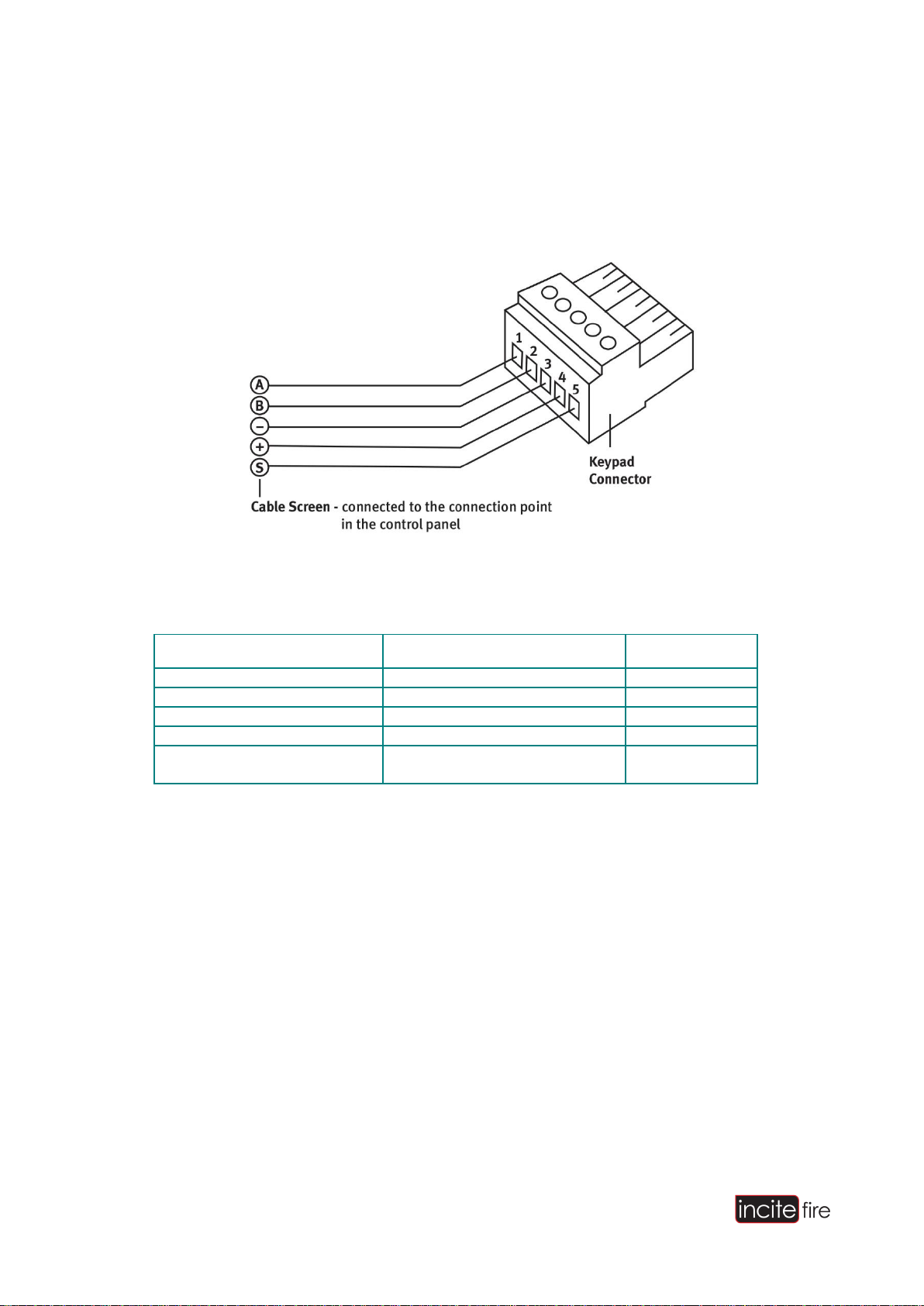
All shield cables must be connected to the control panel housing. Similarly, the shield cable at the keypad end
must be connected to connector pin S (shield). The shield cable must have continuity via the connection point of
each mounting base on the lighting lines.
The cable between the transformer and the control panel must be of the MSK 2 x 1mm type. The cable must be
less than 1m long. The cable is delivered with the control panel.
FIREscape System Installation Manual
Page 9 of 56
3.2 Installation Environment
The operating environment of the system and its connected components must be considered at the design
stage prior to installation
4 Panel Housing
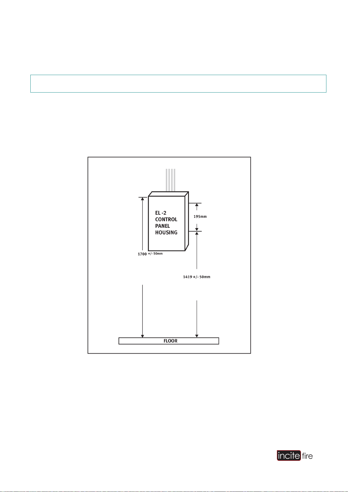
4.1 Installation
The weight of the control panel is approximately 8 kg, including 1 x 7 Ah battery. The weight of the control panel
must be considered when for wall mounting. The cable between the control panel and the transformer must not
exceed 1 m. The cable is provided with the control panel.
Figure 2 - An example installation
Drill 4 x 6mm holes for the mounting plugs. The hole depth must be 20–25 mm. Refer to
Figure 3 on page 8 for the location of the holes. Once drilled, insert appropriate fixing plugs.

FIREscape System Installation Manual
Page 10 of 56
Figure 3 - Fixing Hole Template
Insert 4 x 2mm screws into theplugs.
Lift the control panel housing to the wall and guide the screws into the screw grooves in the
housing.
Tighten the screws.
Route the cables between the wall and the panel housing and then through the cable aperturein to the
panel housing.Shorten the cables to a suitablelength.
Strip the cables ready forconnection.
The insulation resistance must be measured before connecting the cableconnectors.

FIREscape System Installation Manual
NOTE: The aperture at the bottom of the housing is for the transformer cable. The apertures at the top of the
housing are for other cables.
Figure 4 - Measuring Insulation Resistance
The insulation resistance is measured for each conductor, including the shield, against the building earth. The
insulation resistance must be >1 MΩ.
After this, the cable shield can be connected to the shield connection, see Figure 4 on page 9.
5 EL-KP Keypad
5.1 Overview
EL-KP keypad(s) are used to control and interact with the emergency lighting system. A maximum of 8 keypads
can be connected to the system. The keypads are rear entry only by connection and connect directly to the
CPN serial communication port of the motherboard.
A 4 core cable plus SHEILD is required for the connection of a keypad to the control panel. The keypad can be
powered directly from a local power supply or the control panel’s auxiliary supply. The local power supply must
be double-insulated without need for grounding and must have battery backup. When using any other type of
power supply, the RS485 traffic between the control panel and the keypad must be isolated with the EL-ISOL.
NOTE: When using separate power supplies without the EL-ISOL card, the negative leads of the power
supplies must be connected with the negative leads of the control panel.
Page 11of 56
Page 12 of 56
FIREscape System Installation Manual
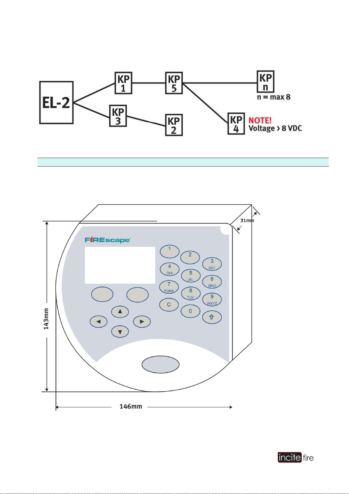
The keypads are connected in parallel to the serial communication bus. The cabling can be a star
(through a central node) or ring (through each device). The units do not have to be addressed sequentially.
Figure 11 - EL-KP Keypad Connectivity
NOTE: The maximum length of the data bus is 500m.
When calculating the voltage drop, the maximum power consumption of the keypad must be used.
Figure 12 - EL-KP Dimensions
FIREscape System Installation Manual
Page 13 of 56
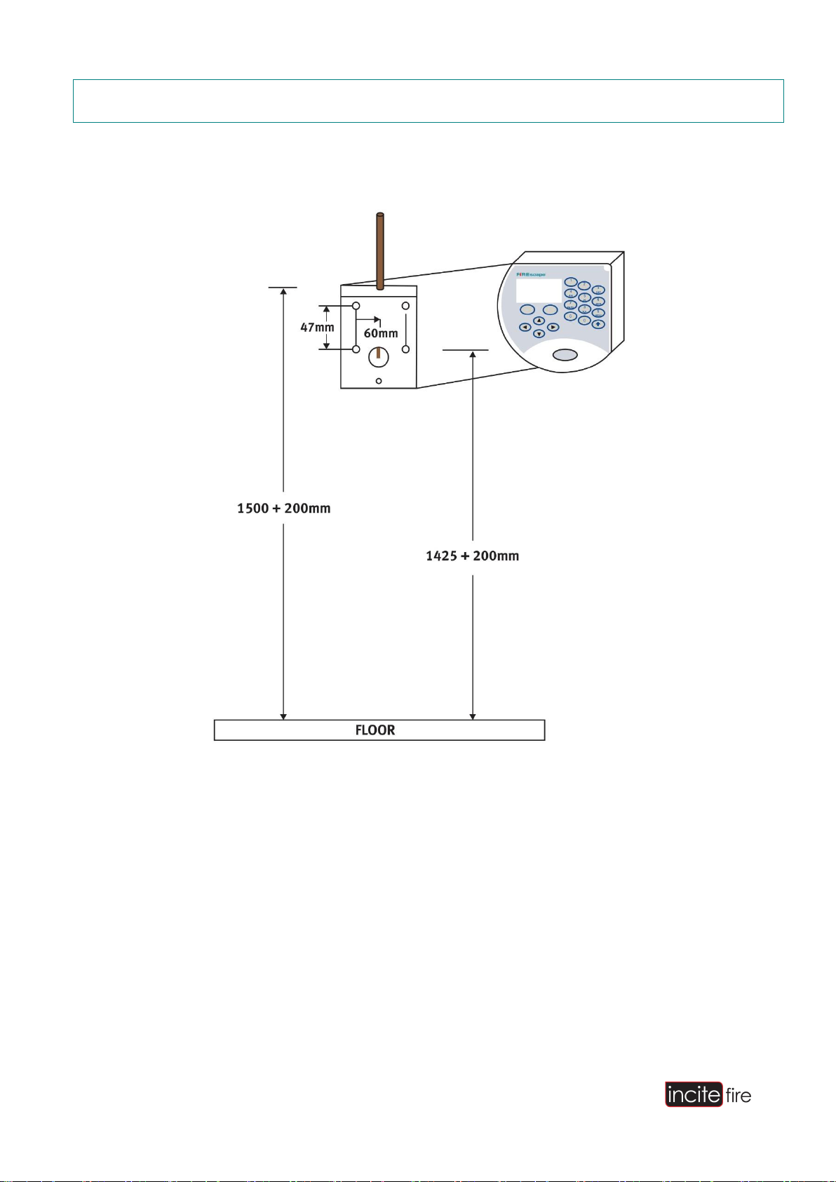
6 Installation
The keypad should be installed at an average shoulder level height of around 1500 (+200)mm.FIREscape
System Installation Manual
Figure 13 - EL-KP Typical Installation
Drill 4 holes for the mounting plugs. The hole depth must be 20–25 mm. For the location of the holes,
see Figure 14.
Attach the plugs.
Take the cable through the bottom plate. There is a pre-scored section at the top of the casing for surface
installation. This should be snapped off and filed if it is required.
Attach the base plate with 4 x 3.9 mmscrews.
Shorten the cables so that they are suitable for installation. Strip the cables for connection.
Connect the 5-pin connector according toinstructions.
Terminate the cable at the control panel according to control panelinstructions.
FIREscape System Installation Manual
Page 14 of 56
Set the address, configure any other settings required, and connect the 5-pin connectorto the keypad.
Attach the keypad to the base plate with 3 mm machinescrews.
The front cover fixing screw is concealed with the supplied self-adhesive coversticker.
6.1 Connection
Figure 14 –Keypad Connector
Description
EL-2
EL-KP
Data RS485 A
X1, 8
1
Data RS485 B
X1, 7
2
Voltage -
X1, 6
3
Voltage + 12VDC
X1, 5
4
Cable shield
Connection point for the control
panel housing’s cable shield
5
FIREscape System Installation Manual
Page 15 of 56
7 Settings
Figure 15 - EL-KP Settings
The address of the keypad is set with the rotary switch SW1.
Connect the 5-pin plug into connectorX2.
Adjust the display contrast, if necessary, after applyingpower.
Attach the keypad to the base plate with 3mm machinescrews.
Address
SW1 (backlight off)
SW1 (backlight on)
1
0
8
2
1
9
3
2
A
4
3
B
5
4
C
6
5
D
7
6
C
8
7
F

FIREscape System Installation Manual
Page 16 of 56
7.1 Start
When the keypad starts (voltage connected or restart), the display will show this text:
If the data connection to the control panel is working, the keypad’s address is shown, for example Addr 1, along
with the software version and the text “Polling OK” on the bottom row. The text will change to
If there is a problem with the data connection, the display will read
after which the keypad will restart. This will be repeated until the connection works.
For information on troubleshooting data connection problems, see the section “Troubleshooting” on page 49.
*
KLG
remote
panel *
c.
2005 Oy
Hedpro
Ab.
C
onne
c
t
i
ng
...
“
N
o
po
lli
ng
…
”

FIREscape System Installation Manual
Page 17 of 56
8 EL-2 Connections
Figure 16 - EL-2 Motherboard Connections
8.1 Control Panel Fuses:
Description
Fuse
Value [A]
Points
Connector
35 VAC
F1
6.3
1, 2
X8
Batteries 12VDC
F2
6.3
1 (+), 2(-)
X5
Voltage for external devices
F3
0.5
1, 3 (+), 2, 4(-)
X1
Voltage for external devices
F4
0.5
5, 9 (+), 6 (-)
X1
Voltage for bus A
F5
2.5A
1, 3 (+), 2, 4(-)
X2
Voltage for bus B
F6
2.5A
5, 7 (+), 6, 8(-)
X2

FIREscape System Installation Manual
Page 18 of 56
Voltage for device connected
to PRG card
MF2
0.3 (automatic fuse)
4
X3
Voltage for EL-EXP card
MF3
0.3 (automatic fuse)
-
X4
NOTE: The total maximum load for outputs F3+F4 is 0.6 A.
8.2 Relay Outputs
The control panel has 2 relay outputs. These can be configured as normally open (N/O) or normally closed
(N/C). The outputs are rated at:
Output
Action
Rating [Amps]
Points
Connector
EXT1
Relay, C
1
14
X1
EXT1
Relay, NC
1
15
X1
EXT1
Relay, NO
1
16
X1
FAIL
Relay, C
1
17
X1
FAIL
Relay, NC
1
18
X1
FAIL
Relay, NO
1
19
X1
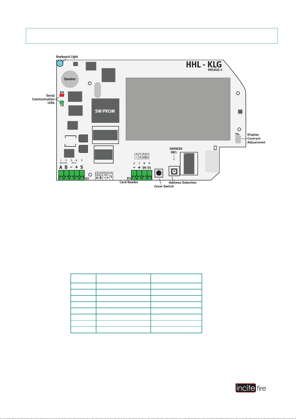
8.3 LEDs
The LEDs on the motherboard indicate functions and serial communication. RX indicates serial communication
reception (red)
TX indicates serial communication transmission (green)
CPN (green), TX = Data sent from CPN port(NL-KLG)
PRN (red), TX = Data sent from PRNport
PRG (red), RX = Data received to the PRG port from adevice
PRG (green), TX = Data sent from the PRG port from adevice
FAIL (red) = Software fault, program executiontermination
PR OFF (yellow) = Write-protected configuration memory unlocked forediting.
FIREscape System Installation Manual
Page 19 of 56
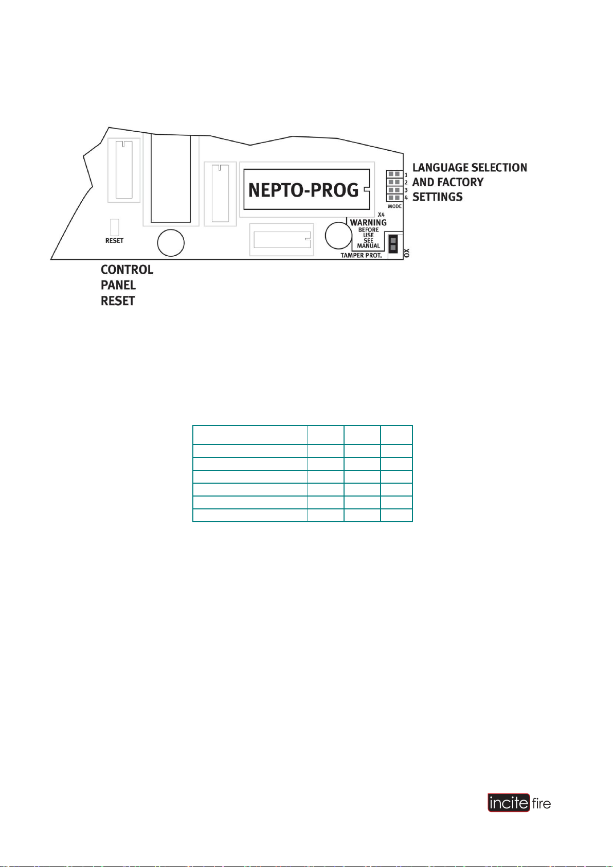
8.4 Settings
Figure 17 - EL-2 Motherboard Settings
8.5 Language Selection
The language of the control panel is set with the jumpers 1–3. The following settings are possible:
Language
1
2
3
English
ON
ON
OFF
Finnish
ON
OFF
OFF
Swedish
OFF
ON
OFF
Norwegian
OFF
OFF
ON
Test mode
ON
ON
ON
4.8 Factory Reset
The control panel can be initialised with factory settings:
Short the RESET pins.
Short the language selection pins 1, 2, 3.
Press and hold down the cover switch.
Open the RESET pins.
Release the cover switch.
FIREscape System Installation Manual
Page 20 of 56
9 RS-232 Connectors
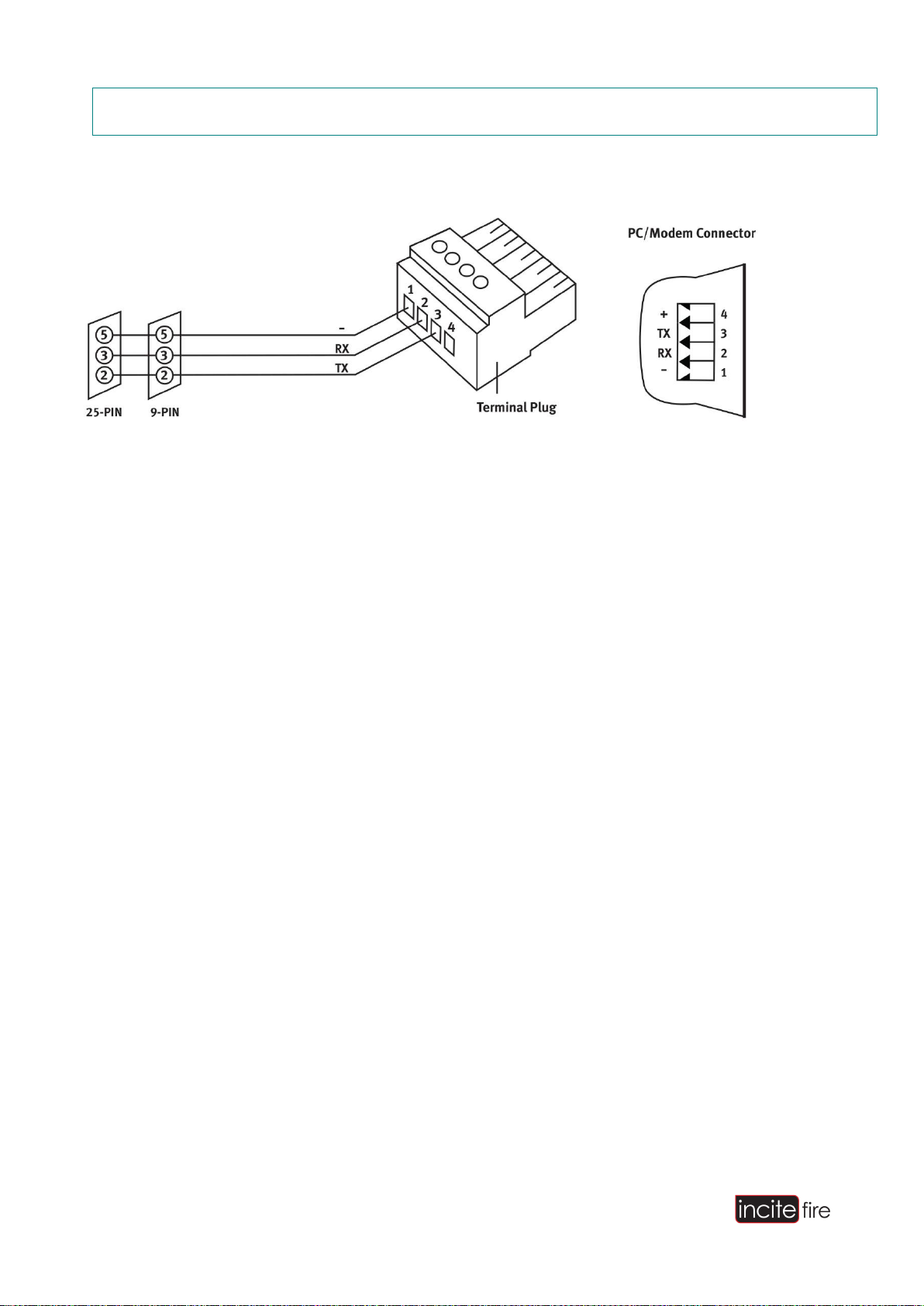
9.1 PC Interface, PRG
Figure 18 - PC Interface Cable Connection
9.2 EL-ISOL (RS-232 Isolator)
When connecting the control panel’s RS-232 outputs to devices which are earthed, such as PC/printer, the
connection may cause interference due to earth leakage. This is because the negative (-) pin of the RS-232
connector is usually connected to shield ground.
The connection must be arranged through a local modem or the EL-ISOL unit if the RS-232 device and the
control panel are not connected to the same power supply group. Usually this means the same room. In no
instance should the cable length without local modem exceed 20 m.
PC SERIAL
PORT

FIREscape System Installation Manual
Page 21 of 56
9.3 EL-ISOL Connection:
Figure 19 - EL-ISOL Connection
9.4 Additional Port, PRN
This port can be used for connecting external RS-232 devices

FIREscape System Installation Manual
Page 22 of 56
10 Addressable Emergency Lighting Lines
10.1 Principle
The system luminaires and interfaces are intelligent units equipped with their own batteries (luminaires) and
have addresses. The control panel polls the units at approximately 0.75 s intervals per address. All units in the
bus (127 devices max) are polled in <100 s. The luminaires also work standalone if the control panel cable
breaks.
The luminaires are installed using the Hochiki EL-TSB base.
The factory default address of all luminaires is 127. The luminaires must be programmed with the TCH- B200
programming device before installation onto the mounting base.
The maximum length of each lighting line is 1 km, and the maximum loop resistance of the conductors is 74 Ω.
The cable’s conductor capacitance must be <0.7 µF. The power consumption also restricts the cable distance.
A maximum of 127 units can be connected to a single lighting line depending on the power consumption of the
unit.
10.2 Mounting Base (EL-TSB)
The mounting base required for the luminaires is the Hochiki EL-TSB standard mounting base.
NOTE: The alignment ‘rib’ on the mounting base must face at a 90° angle in relation to the exit direction. The
base has slight adjustment margin for this angle. Use a template when drilling.
All devices must be installed on an even surface so that they will notdistort.
The bases can be wall or ceilingmounted.
The bases should be fixed with appropriate size and type screws for the intended fixingsurface.
To avoid damage to the base do not over-tighten the fixingscrews.
Table of contents
Popular Lighting Equipment manuals by other brands


Chauvet Professional
Chauvet Professional STRIKEARRAY4 Quick reference guide

Big Red Rooster
Big Red Rooster BRRC117 owner's manual

MaxLite
MaxLite CID1 operating instructions

Starway
Starway DAYTONA user manual

GLX
GLX GLS-47 owner's manual

Larson Electronics
Larson Electronics MMLP-1MLED-12P instruction manual