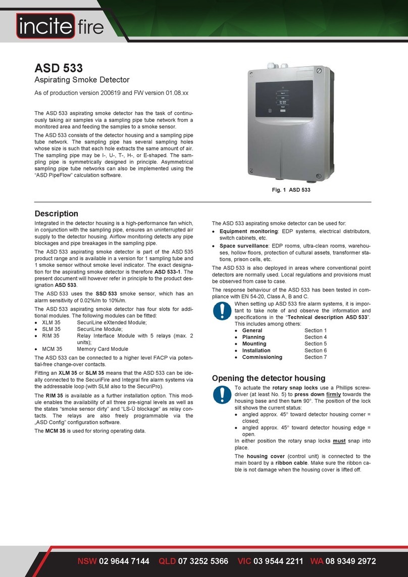
Incite Fire ASD 532 User manual

ASD 532
Aspirating Smoke Detector
Operating Manual

2/ 88 ASD532 Operating Manual

Imprint
3 / 121
Imprint
Notice
This documentation, T
140 421, is valid only for the product described in Section 1.
This documentation is subject to change or withdrawal
without prior notice. The statements made in this docu-
mentation are valid until such time as the statements are revised by a new edition of the documentation
(T
number with new index). The user of this document is responsible for staying up to date with it
s current status
through the editor/publisher. We accept no responsibility for claims against any incorrect statements in this
document that were unknown to the publisher at the time of publication. Handwritten changes and additions are
not valid. This doc
umentation is protected by copyright.
Foreign language documentation as listed in this document is always released or changed at the same time as
the German edition. If there are inconsistencies between the foreign language documentation and the German
doc
umentation, the German documentation is binding.
Some words in this documentation are highlighted in
blue. These terms and designations are the same in all lan-
guages and are not translated.
Users are encouraged to contact the editor/publisher if there are statements which are unintelligible, misleading,
incorrect or contain errors.
© Securiton AG, Alpenstrasse 20, 3052 Zollikofen, Switzerland
Document T 140 421 is available in the following languages: German T 140 421 de
English T 140 421 en
French T 140 421 fr
Italian T 140 421 it
Spanish T 140 421 es
Portuguese T 140 421 pt
Swedish T 140 421 sv
Current edition: First edition 15.10.2015 Bmi/ksa
Notice
Validity for production version and firmware version
The following documentation is applicable only to the
ASD 532 aspirating smoke detector with the following pro-
duction version and firmware version:
Production version Firmware version
from 151015 from 01.00.08
ASD532 Operating Manual

Imprint
4 / 121
Other documents
Data sheet ASD 532
T 140 422
de / en / fr / it / es / pt / sv
Material for the sampling pipe
T 131 194
Multilingual (ED / FI)
Commissioning protocol
T 140 423
Multilingual (EDFI)
Data sheets
XLM 35
T 140 088
de / en / fr / it / es / pt / sv
RIM 36
T 140 364
de / en / fr / it / es / pt / sv
SIM 35
T 140 011
de / en / fr / it / es / pt / sv
SMM 535
T 140 010
de / en / fr / it / es / pt / sv
Aspirating Fan Unit AFU 32 mounting instructions
T 140 426
Multilingual (EDFI)
ASD532 Operating Manual

Safety information
5 / 121
Safety information
Provided the product is deployed by trained and qualified persons in accordance with this documentation T 140 421 and the
danger, safety and general information notices in this technical description are observed, there is no danger to persons or
property under normal conditions and when used properly.
National and state-specific laws, regulations and directives must be observed and adhered to in all cases.
Below are the designations, descriptions and symbols of danger, safety and general information notices as found in this docu-
ment.
Danger
If the Danger notice is not properly observed, the product and any other system parts may present a hazard for
persons and property, or the product and other system parts may be damaged to the extent that malfunctioning
results in
danger to persons and property.
•
Description of which dangers may occur;
•
Measures and preventative actions;
•
How dangers can be averted;
•Any other safety-related information.
Warning
The product may be damaged if the warning information is not heeded.
•
Description of which damage can occur;
•
Measures and preventative actions;
•
How dangers can be averted;
•Any other safety-related information.
Notice
The product may malfunction if this notice is not observed.
•
Description of the notice and which malfunctions can be expected;
•
Measures and preventative actions;
•Any other safety-related information.
Environmental protection / recycling
Neither the product nor its components present a hazard to the environment provided they are handled properly.
•
Description of which parts have environmental protection issues;
•
Description of how devices and their parts have to be disposed of in an environmentally-friendly way;
•Description of the recycling possibilities.
Batteries
It is not permitted to dispose of batteries in the domestic rubbish. As the end user you are legally obliged to return
used batteries. Used batteries can be returned to the seller or taken to a designated recycling centre (e.g. a
community collection point or dealer) at no cost. You may
also send them back to the seller by post. The seller
will refund the postage when you return your old batteries.
ASD532 Operating Manual

6 / 121 ASD532 Operating Manual

Document history
7 / 121
Document history
First edition Date 15.10.2015
ASD532 Operating Manual

8/ 121 ASD532 Operating Manual

Contents
9 / 121
Contents
_________________________________________________________________________________________
1General 13
1.1 Purpose 13
1.2 Uses and applications 14
1.3 Abbreviations, symbols and terms 14
1.4 Product identification 16
1.5 Smoke sensors used 17
1.6 Hardware / firmware 17
_________________________________________________________________________________________
2Function 18
2.1 General operating principle 18
2.2 Electrical functional principle 19
2.2.1 Power supply 19
2.2.2 Fan control 20
2.2.3 Microcontroller 20
2.2.4 Programming / operation 21
2.2.5 Displays 22
2.2.6 Relay 22
2.2.7 Outputs 23
2.2.8 Inputs 23
2.2.9 Interfaces 23
2.2.10 Airflow monitoring 24
2.2.11 Smoke sensor monitoring 24
2.2.12 Alarm release 25
2.2.12.1 Alarm 2 25
2.2.12.2 Alarm cascading 25
2.2.12.3 Isolating the smoke sensor 25
2.2.13 Autolearning 26
2.2.14 Day/night control & weekday control 27
2.2.15 Fault triggering 27
2.2.16 Event memory 27
2.2.17 Data logging on the SD memory card 28
2.2.18 Reset types 29
2.2.18.1 State reset 29
2.2.18.2 Hardware reset 29
2.2.18.3 Initial reset 29
2.2.19 ASD network 29
_________________________________________________________________________________________
3Design 30
3.1 Mechanical 30
3.2 Electrical 32
3.3 Hardware / firmware 34
3.4 List of materials / components 35
3.5 Packaging 35
ASD532 Operating Manual

Contents
10 / 121
_________________________________________________________________________________________
4Planning 36
4.1 General aspects of planning 36
4.1.1 Standards, regulations, guidelines, approvals 36
4.2 Area of application 36
4.2.1 System limits 37
4.3 Planning aids 37
4.3.1 Planning with “ASD PipeFlow” calculation 37
4.3.2 Planning without “ASD PipeFlow” calculation 38
4.4 Space surveillance 38
4.4.1 Space surveillance applications 38
4.4.2 Principles of space surveillance 39
4.4.3 Types of sampling pipe layouts for space surveillance 40
4.4.4 System limits for space surveillance without “ASD PipeFlow” calculation 41
4.4.4.1 Normative system limits for space surveillance without “ASD PipeFlow” calculation 41
4.4.4.2 Non-normative system limits for space surveillance without “ASD PipeFlow” calculation 41
4.4.4.3 System limits for planing without “ASD PipeFlow” calculation 42
4.4.4.4 Non-normative system limits table for planning without “ASD PipeFlow” calculation 43
4.4.4.5 Sampling holes for planning without “ASD PipeFlow” calculation 44
4.4.4.6 Maintenance sampling hole 45
4.5 Equipment monitoring 45
4.5.1 Equipment monitoring applications 45
4.5.2 Principles of equipment monitoring 46
4.5.3 Examples of sampling pipe layouts for equipment monitoring 46
4.5.4 System limits for equipment monitoring without ASD PipeFlow calculation 47
4.5.4.1 Alarm thresholds for equipment monitoring using sampling fixtures without ASD PipeFlow calculation 47
4.5.5 Sampling fixtures and sampling holes in equipment monitoring 48
4.6 Air recirculation 48
4.7 Settings 49
4.8 Electrical installation 50
4.8.1Installation cable requirements 50
4.8.2 Determining the conductor cross-section 51
4.9 Restrictions 52
4.10 Environmental influences 53
_________________________________________________________________________________________
5Mounting 54
5.1 Mounting guidelines 54
5.2 Dimensioned drawing / drilling plan for the detector housing 54
5.3 Material for the sampling pipe 55
5.4 Mounting the detector housing 56
5.4.1 Opening and closing the detector housing 57
5.4.2 Mounting positions for the detector housing 58
5.4.3 Removing the air outlet pipe plug 59
5.4.4 Turning the labelling strip 59
5.5 Mounting the sampling pipe 60
5.5.1 General 60
5.5.2 Mounting with PVC tubes and fittings 60
5.5.3 Mounting with ABS tubes and fittings 60
5.5.4 Mounting with metal pipes and fittings 61
5.5.5 Linear expansion 61
5.5.6 Mounting the sampling pipe 62
5.5.7 Mounting for equipment monitoring 63
5.5.7.1 Screw-free fastening of the sampling pipe 63
5.5.7.2 Transition to a flexible tube 64
5.5.8 Creating the sampling holes 65
5.5.9 Mounting the sampling hole clips and maintenance clips 65
5.5.10 Mounting the sampling funnel 65
5.5.11 Mounting sampling stubs for a ceiling bushing 66
5.5.12 Mounting the filter-box, filter unit, dirt trap box, dust retaining box, water retaining box 67
ASD532 Operating Manual

Contents
11 / 121
_________________________________________________________________________________________
6Installation 68
6.1 Regulations 68
6.2 Cable entry 68
6.3 Using the smoke sensor 69
6.4 Installing additional modules XLM 35, RIM 36, SIM 35 70
6.5 Electrical connection 70
6.5.1 Terminal assignment Main Board AMB 32 71
6.5.2 Terminal assignment for eXtended Line Module XLM 35 72
6.5.3 Terminal assignment for RIM 36 Relay Interface Module 72
6.5.4 Terminal assignment of an SIM 35 Serial Interface Module 72
6.6 Connection variants 73
6.6.1 Power supply 73
6.6.2 Reset input 73
6.6.3 Control 74
6.6.3.1 Control via voltage supply by means of auxiliary relay 74
6.6.3.2 Control via “Reset external” input 75
6.6.4 Connection to the FACP line 76
6.6.4.1 Connection to zone detection via Al / St relays 76
6.6.4.2 Connection to selective identification or addressable loop via Al / St relay 76
6.6.4.3 Connection to SecuriFire / Integral addressable loop from XLM 35 77
6.6.5 OC outputs 77
_________________________________________________________________________________________
7Commissioning 78
7.1 General 78
7.2 Programming 79
7.2.1 Configuration options 80
7.2.2 Relay allocation 82
7.3 Starting up 82
7.3.1 Commissioning with EasyConfig 82
7.3.2 Commissioning with “ASD Config” configuration software 83
7.3.3 Setting to pre-defined switch positions A11 to C31, W01 to W44 84
7.3.4 Setting and polling the date and time 85
7.3.5 Initial reset 86
7.3.6 Displaying the firmware version 86
7.3.7 Logging off additional modules XLM 35, RIM 36, SIM 35 and the SD memory card 87
7.4 Re-programming 87
7.4.1 Re-programming on the ASD 532 87
7.4.2 Re-programming with “ASD Config” configuration software 87
7.4.3 Re-programming from SecuriFire / Integral with XLM 35 87
7.5 Download new firmware to the ASD 532 88
7.5.1 FW upgrade from SD memory card 88
7.5.2 FW upgrade from PC via “ASD Config” configuration software 89
7.6 Measurements 90
7.6.1 Reading out the set configuration and airflow 91
7.7 Testing and checking 92
7.7.1 Checking the alarm release 92
7.7.2 Test triggerings 93
7.8 Commissioning protocol 93
ASD532 Operating Manual

Contents
12 / 121
_________________________________________________________________________________________
8Operation 94
8.1 Operation and display elements 94
8.2 Functional sequence of operation 95
8.3 Switch positions 96
8.4 Reset 97
8.5 Displays 97
8.5.1 Displays on the control unit 97
8.5.2 Indicators on the AMB 32 main board 98
8.5.3 SD memory card operation 98
8.5.3.1 Data logging on the SD memory card 98
8.5.4 Displaying and reading out the event memory 99
8.5.4.1 Procedure and interpretation of the event memory display 99
8.5.4.2 Event groups 100
8.5.4.3 Event codes within event groups 100
8.5.5 Operation and displays on the XLM 35 103
8.5.6 Operation and display on the SIM 35 104
8.5.7 Operation and display on the SMM 535 105
8.6 Operation from SecuriFire / Integral with XLM 35 105
_________________________________________________________________________________________
9Maintenance and service 106
9.1 General 106
9.2 Cleaning 106
9.3 Maintenance checks and function checks 107
9.4 Replacing units 109
9.4.1 Replacing the smoke sensor 109
9.4.2 Replacing the aspirating fan unit 109
9.4.3 Replacing the airflow sensor 110
9.4.4 Replacing the AMB 32 Main Board 110
9.5 Disposal 111
9.5.1 Materials used 111
_________________________________________________________________________________________
10 Faults 112
10.1 General 112
10.2 Warranty claims 112
10.3 Finding and rectifying faults 113
10.3.1 Fault states 113
_________________________________________________________________________________________
11 Options 116
11.1 sampling pipe 116
11.2 Use under extreme conditions 116
11.3 Use of detector boxes 116
11.4 ASD network 117
11.4.1 ASD networking via RS485 interface from SIM 35 117
11.4.2 ASD networking via Ethernet interface from AMB 32 118
_________________________________________________________________________________________
12 Article numbers and spare parts 119
12.1 Detector housings and accessories 119
12.2 Sampling pipe and accessories 119
_________________________________________________________________________________________
13 Technical data 120
_________________________________________________________________________________________
14 List of figures 121
ASD532 Operating Manual

General
13 / 121
1 General
1.1 Purpose
The ASD 532 aspirating smoke detector has the task of continuously taking air samples via a sampling pipe tube network from
a monitored area and feeding the samples to a smoke sensor. Thanks to this detection method and the product’s excellent
properties under severe ambient conditions, the ASD 532 aspirating smoke detector is used wherever problems are to be ex-
pected owing to poorly accessible monitored areas or latent disturbance variables during operation such that optimal protec-
tion can no longer be guaranteed with conventional point detectors.
The SSD 532 smoke sensor is used in the ASD 532. It is available in the three following versions and sensitivity ranges:
•SSD 532-1 Alarm sensitivity range 0.5%/m to 10%/m
•SSD 532-2 Alarm sensitivity range 0.1 %/m to 10%/m
•SSD 532-3 Alarm sensitivity range 0.02%/m to 10%/m.
The ASD 532 aspirating smoke detector has two slots for additional modules. The following modules can be fitted:
•XLM 35 eXtended Line Module
•RIM 36 Relay Interface Module with 5 relays;
•SIM 35 Serial Interface Module.
With the installation of a eXtended Line Module XLM 35 the ASD 532 aspirating smoke detector can be ideally connected to
the fire alarm systems SecuriFire (SecuriLine eXtended) and Integral (X-Line) via the addressable loop. Control operations and
changes to the ASD device configuration can be carried out directly from the FACP (in preparation). For this purpose the
FACP user software “SecuriFire Studio” and “Integral Application Center” are used to start the “ASD Config” configuration
software for access to the ASDs; the configuration software is then used to make changes to the ASD 532.
A further installation option is the RIM 36 relay interface module. This module enables the availability of all three pre-signal
levels as well as the states “smoke sensor dirty” and “LS-Ü pipe blockage” as relay contacts. The relays are also freely pro-
grammable via the “ASD Config” configuration software.
The SIM 35 Serial Interface Module is for networking multiple ASD 532 aspirating smoke detectors via RS485 bus. Using the
“ASD Config” configuration software, all ASD 532 units present in the network can be visualised and operated from a PC. The
master module in the ASD network is the SMM 535, by means of which a PC is connected.
Notice
The normative alarm transmission of the
ASD 532
to the superordinate centre does not take place via the ASD
network. For that purpose the
“Alarm” / “Fault”
relays in the ASD or the SecuriFire / Integral addressable loop are
to be used from the XLM 35.
The present technical description contains all information essential for trouble-free operation. For obvious reasons only those
details specific to individual countries and companies or special applications can be discussed if they are of general interest.
ASD532 Operating Manual

General
14 / 121
1.2 Uses and applications
Thanks to the detection method, air sampling by means of a sampling pipe tube network and the good properties of the prod-
uct under extreme ambient conditions, the ASD 532 aspirating smoke detector is used wherever problems can be expected
owing to poorly accessible areas to be monitored or latent disturbance variables during operation such that optimal protection
cannot be guaranteed with conventional point detectors. This includes:
•Space surveillance:
EDP rooms, ultra-clean rooms, warehouses, hollow floors, protection of cultural assets, transformer stations, prison cells,
etc.
•Equipment monitoring:
EDP systems, electrical distributors, switch cabinets, etc.
The ASD 532 can also be deployed in areas where normally conventional point detectors are used. Local regulations and pro-
visions must be observed from case to case.
The response behaviour of the ASD 532 has been tested in compliance with EN 54-20, Class A, B and C.
When control-unit-specific alarm transmitters, line monitoring elements etc. are used, the ASD 532 can be connected via its
potential-free change-over contacts to all common fire alarm systems virtually without restrictions.
1.3 Abbreviations, symbols and terms
The following abbreviations, symbols and terms are used in the Technical Description T 140 421. The abbreviations for tube
material and accessories are listed in a separate document: T 131 194 (see also Sec. 5.3).
µC
=
Microcontroller / microprocessor
ABS
=
Acrylonitrile-butadiene styrene (plastic)
AFS 32
=
Air Flow Sensor
AFU 32
=
Aspirating Fan Unit
Al
=
Alarm
AMB 32
=
ASD main board
ASD
=
Aspirating Smoke Detector
ASD Config
=
configuration software for the ASD 532
ASD PipeFlow
=
Calculation software for the sampling pipe, “ASD PipeFlow” as of Version 2.3
CE
=
Communauté Européenne (European Community)
DA
=
Detection area
Default
=
Preset values / settings
DET
=
Detector
DIN
=
Deutsche Industrie Norm (German industry standard)
DZ
=
Detection zone
EasyConfig
=
Commissioning process without the “ASD Config” configuration software
EDP
=
Electronic data processing
EEC
=
European Economic Community
EEPROM
=
Memory component for system data and ASD configuration
EMC
=
Electromagnetic compatibility
EN 54
=
European standards for fire alarm systems (Germany = DIN, Switzerland = SN, Austria = Ö-Norm)
Ex-zone
=
Area subject to explosion hazards
FACP
=
Fire alarm control panel
FAS
=
Fire alarm system
Fault
=
Fault
Flash PROM
=
Memory component for firmware
Flush mounting /
surface mounting
= Flush mounted / surface mounted
FW
=
Firmware
GND
=
Supply ground (minus (-) pole)
ASD532 Operating Manual

General
15 / 121
Continuation:
H-Al
=
Main alarm
HF
=
High frequency
HW
=
Hardware
IEC
=
International Electrotechnical Commission
Initial reset
=
First start-up on commissioning
IPS 35
=
Insect Protection Screen
LED
=
Light-emitting diode (indicator)
LS
=
Airflow
LS-Ü
=
Airflow monitoring
Manufacturer
=
Securiton
OC
=
Open collector output
OEM
=
Original Equipment Manufacturer (reseller)
PA
=
Polyamide (plastic)
PC
=
Personal computer
PC
=
Polycarbonate (plastic)
PE
=
Polyethylene (plastic)
Pin
=
Terminal pin
PMR 81
=
Semi-conductor relay
Port
=
Input or output component
PVC
=
Polyvinyl chloride (plastic)
RAM
=
Memory component
RIM 36
=
Relay interface module
RoHS
=
Restriction of Certain Hazardous Substances (eco-friendly manufacturing processes)
SecuriFire
=
FAS system
SecuriLine
=
Fire detector addressable loop
SIM 35
=
Serial Interface Board
SMM 535
=
Serial Master Module
SSD 532
=
Smoke sensor
St
=
Fault
St-LS
=
Airflow fault
SW
=
Software
Te.
=
Terminal
UMS 35
=
Universal Module Support
Update /Release
=
Renewal / update of the firmware
V-Al
=
Pre-alarm
VDC
=
Direct current voltage
VdS
=
Verband der Schadenversicherer (Association of Indemnity Insurers, Germany)
VKF
=
Vereinigung Kantonaler Feuerversicherungen (Cantonal Fire Insurance Union, Switzerland)
VS
=
Pre-signal
Watchdog
=
Monitoring of the microcontroller
XLM 35
=
eXtended Line Module
ASD532 Operating Manual

General
16 / 121
1.4 Product identification
For identification purposes, the ASD 532 and its units have rating plates or identification plates.
The following product identifications apply:
Rating plate on the ASD 532 and identification on the packaging
Additional conformity marks may be affixed to a second rating plate or to an extended area of the rating plate (wider plate).
Identification on the packaging of the mounted printed circuit boards
Notice
The
rating plates, type designations and/or identifications on devices and printed circuit boards must not be re-
moved, written over or defaced in any way.
Many products, such as accessories and mounting materials, are identified only with a sticker showing the article number. The
manufacturer identifies these parts by article number.
3052 Zollikofen / Switzerland
11-2000003-01-01.
XXYYZZ
XX.YY.ZZSecuriton: 022.XXXXXX
Schrack: YYYYYYY
EN 54-20 Class: A, B and C
G xxxxxx
U: 14 - 30 VDC
Operating current (24 VDC):
Idle / fault:
Alarm:
Data sheet T 140 422
100 mA
115 mA
ASD 532
XXXXXXXXXX
Made in Germany
Approvals, approval mark
Manufacturer
Type designation
Response class
Operating voltage / current consumption
Document number (data sheet)
Approval number
Article number (Hekatron)
Article number (Securiton/Schrack)
Production date (day.month.year)
Production version (day/month/year)
ID number
1
SECURITON XYZ 35
4000XXX.XXXX.XXYYZZ YY/ZZ
Securiton: XXX.XXXXXX
Schrack: YYYYYYY
Approvals, approval mark
Type designation
Article number (Hekatron)
Article number (Securiton/Schrack)
Production date (month/year)
Production version (day/month/year)
Manufacturer
ASD532 Operating Manual

General
17 / 121
1.5 Smoke sensors used
Danger
Only those smoke sensors in the device approval and in the list below may be used in the
ASD 532 aspirating
smoke detector. The use of third-party detectors voids the ASD 532 approval issued by the manufacturer.
Smoke sensors of the following type can be fitted in the ASD 532 (see also Sec. 4.9 and 6.6.4):
•SSD 532-1 Alarm sensitivity range 0.5%/m to 10%/m
•SSD 532-2 Alarm sensitivity range 0.1 %/m to 10%/m
•SSD 532-3 Alarm sensitivity range 0.02 %/m to 10%/m
The response sensitivity of the concerned smoke sensor can be adjusted within the above specified range. Depending on the
application in accordance with EN 54-20, Class A, B or C, the value is specified via AMB 32 (pre-defined switch positions as
described in Sec. 4.4.4 to 4.4.4.3) or based on planning specifications using the ASD PipeFlow calculation software via the
ASD Config configuration software (see Sec. 7.2.1). The selection of the smoke sensor type with the respective range of sensi-
tivity is based on the information in Sec. 4.4.4.3 or “ASD PipeFlow”.
1.6 Hardware / firmware
The hardware is considered to comprise the complete detector housing and all the units belonging to the ASD 532 aspirating
smoke detector such as sampling pipe and mounting material.
The firmware is located on the Flash PROM in the ASD 532. An EEPROM is fitted for storing and saving system-specific pa-
rameters.
Danger
The
ASD 532 is to be operated only with the appropriate original firmware from the manufacturer.
Any unauthorised intervention in the firmware or the use of non
-
original firmware may result in malfunction and/or
in damage to the device. Furthermore, all guarantee and warranty rights with respect to the manufacturer of the
ASD 532 will become null and void as a result.
© Copyright by Securiton
All ASD 532 firmware is subject to the manufacturer’
s copyright. Any unauthorised intervention in the firmware, misuse,
copying or unauthorised trade with the firmware represents a breach of copyright and will be subject to legal proceedings.
Notice
A version change or extension of the
ASD 532
firmware does not imply a right to an upgrade or new release for
existing ASD 532 systems.
ASD532 Operating Manual

Function
18 / 121
2 Function
2.1 General operating principle
In the sampling pipe tube network, the fan generates a vacuum which results in fresh air continuously reaching the detector
housing via the sampling pipes. In this way the smoke sensor is constantly supplied with new air samples from the monitored
area. Should the smoke concentration exceed the permissible value, the ASD 532 triggers an alarm. The alarm is indicated
visually on the ASD 532 and can be transmitted via a potential-free change-over contact to a superordinate fire alarm control
panel.
The operational reliability of the aspirating smoke detector depends on the functional reliability of the smoke sensors and on
the constant air supply to the system. A fan failure, blockage of the sampling holes or pipe breakage must be communicated to
the fire alarm control panel in the form of a fault signal. This condition is satisfied by the airflow monitoring of the ASD 532.
Fig. 1General operating principle
ASD 532
Housing
Smoke sensor
chamber
Installation location
for additional module Cable entries
Monitoring area
Sampling
holes
Sampling pipe network Smoke sensor Airflow sensor
Fan
Air outlet
AMB ASD Main Board
ASD532 Operating Manual

Function
19 / 121
2.2 Electrical functional principle
Fig. 2Block diagram
2.2.1 Power supply
The operating voltage of the ASD 532 is +14 to +30 VDC. On the AMB 32 Main Board, 5 VDC of the operating voltage is di-
verted for internal voltage use.
The operating voltage is monitored on the AMB 32 for undervoltage. If the operating voltage falls below 13 VDC (+0 /
–0.3 VDC), the ASD 532 triggers an undervoltage fault.
15 14 13 12 11 10 987654321
LED1
IN
OUT
LED2
LED3
LED4
LED5
(8)(8)
2 RIM 36
nd
Fan
Connection possibilities of the additional modules
to or
1 x SIM 35 to or
2 x RIM 36 to cascaded
1 x XLM 35 :
“”“”
“”“”
“”
Option1
Option1 Option2
Option3 ,
Option2
1 2 3 4 5 6
(16)
SIM 35
(16)
L1
C1
G1
L2
C2
G2 LED2
LED1
XLM 35
Air flow
sensor
Smoke sensor
SSD 532
15 14 13 12 11 10 9 8 7 6 5 4 3 2 1
LED1
IN
OUT
LED2LED3LED4LED5
(8)(8)
1 RIM 36
st
Reset
ext.
Rel. 2
Al Rel. 1
St OC Supply
Red. InOEM
Accessories
bus
(16) (16) (8)
AMB 32
Option3Option1 Option2
BAT
Reset
OK
HW-Reset
SENSSSD
Vent
21 20 19 18 17 16 15 14 13 12 11 10 9 8 7 6 54 3 2 1
Ethernet
UP
CardOK
Com
Wdog
Pwr
Al
Flt
Det.
dusty
dirty
1
2
3
4
5
6
7
8
9
10
LED1
LED2
LED3
LED4
ASD532 Operating Manual

Function
20 / 121
2.2.2 Fan control
The physical and electrical properties of a fan cause a brief power surge when it is switched on and starts up, which in turn af-
fects the conductor dimensioning and the total power consumption of the fire alarm system.
A specially designed circuit therefore ensures that the fan cannot exceed a specific maximum power consumption in its start-
up phase. When the ASD 532 is switched on, the computer-controlled fan speed starts up slowly. After the fan has been pow-
ered up, the speed is kept constant.
Any blocking of the fan is detected by evaluating the motor speed. If the specified threshold is undershot, the fan supply is
switched off and a fault is signalled.
Depending on the size of the system and/or environment, the fan can be operated at different speeds (by means of the
“ASD Config” configuration software). This is useful primarily in critical areas (long pipes) to increase the transport speed in the
sampling pipe tube network (high speed) or to reduce the noise level in cases where the noise level produced by the fan is a
disturbance (low speed). The following fan speed levels can be selected:
Level
Speed
(rpm)
Effect
I
5250
Low transport speed / low noise level
II
6900
Normal transport speed / reduced noise level
III
9300
High transport speed / normal noise level
Notice
•
The fan speed levels can be changed only with the “ASD Config” configuration software.
•
For applications and commissioning without “ASD Config” configuration software, Level II must always set.
•
If the fan speed is changed (by using the “ASD PipeFlow”
calculation software), ensure that the maximum
permissible transport time according to EN 54-20 is not exceeded.
•
After the fan speed has been changed, it is imperative
that a new initial reset is carried out (observe waiting
time of at least 2 min).
2.2.3 Microcontroller
The entire program and switching sequence is controlled by a microcontroller. The firmware is stored on a Flash PROM. Sys-
tem-specific configurations are stored in an EEPROM.
The program is monitored by the internal watchdog of the microcontroller. In the event of a failure of the microcontroller circuit,
an emergency fault is triggered. This is signalled on the device by the steady lit Fault LED. The “Fault” relay switches.
ASD532 Operating Manual
Table of contents
Other Incite Fire Smoke Alarm manuals
Popular Smoke Alarm manuals by other brands
detectomat
detectomat HDv 300 OS Series Operation and installation manual
UltraFire
UltraFire UBH1RF user manual
Honeywell
Honeywell compact asd installation instructions
Ei Electronics
Ei Electronics Ei161RC Ionisation installation instructions
BRK electronic
BRK electronic 83RN quick start guide
careium
careium i10 user guide

Notifier
Notifier SFP-400B manual

Housegard
Housegard System Link SA423WS user manual
Elektrotechnik Schabus
Elektrotechnik Schabus GX-D500P operating instructions
System Sensor
System Sensor 2351E Installation and maintenance instructions
System Sensor
System Sensor 2D51A Installation and maintenance instructions
Smoke hollow
Smoke hollow 44241G2 Assembly & operation
