8 9
4.6 Using the dust lter
In dry interior rooms to be monitored with high levels of dust, e.g. wood
workshop, dry ice blasting, please attach the enclosed dust lter (item
no. 300259) to the hose inlet and x it with a cable tie.
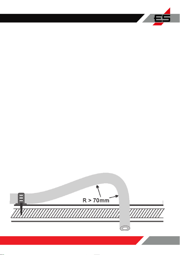
The dust lter can be easily attached to the wall using a screw and dowel
in the screw hole of the lter. Please pay attention to the smallest laying
radius of 70 mm, however, if the warning device and dust lter are in the
same room, the hose may also be signicantly shorter than would be
necessary in thermally demanding rooms. Minimum lengths do not have
to be adhered to in rooms with a normal temperature (10°C ... 40°C), see
also functional area in the technical data, page 22.
The dust lter must not be used in thermally demanding, i.e. particularly
warm or cold, environments. The combination of extraction from a room
and the use of the dust lter requires at least similarly tempered rooms
in which people (can) stay permanently.
Like the GX-D500P itself, the dust lter is only permanently suitable for
temperatures from +10°C to +50°C.
Blow regularly to remove dust from the dust lter
and avoid moisture/moisture on the lter.
The lter should be replaced after a year of operation.
5. COMMISSIONING / FUNCTIONAL TEST / ALARM (Re1)
An electrical function test is carried out for a few seconds when the
mains voltage is applied, after which the warning system is in operation
immediately, monitors the room and, apart from the regular calibrations,
can remain in continuous operation for years. If the green LED lights up
alone, the warning system is ok and ready for use.
Please note: Even if the power failure is brief, the functional test will be
restarted.