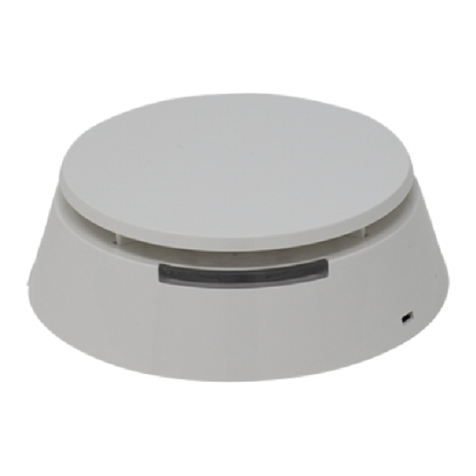
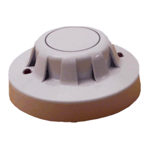
detectomat HDv 300 OS Series Specification sheet

Rauchwarnmelder HDv 300X OS
HDv 300X OSHDv 300X OS
HDv 300X OS
Bedienungs- und Montageanleitung
V 1.7 03.07.2017 BA.-Nr.: 53688 Seite 1 von 4
①
①①
① Sicherheitshinweise - Bitte beachten Sie:
1. Keine Akkus oder Netz eräte zur Spannun sversor un verwenden.
2. Lauter, schriller Ton bei Funktionstests (Druck auf Lichtleitstab). Halten Sie einen
Mindestabstand von 50 cm zwischen Rauchwarnmelder und Ohr ein.
3. Rauchwarnmelder dürfen nicht mit Farbe überstrichen werden.
4. Der Rauchwarnmelder darf an fol enden Orten nicht
nichtnicht
nicht an ebracht werden:
a. Räume, in denen unter normalen Bedin un en starker Wasserdampf entsteht
(z. B. Küche, Bad/WC)
b. In der Nähe von Feuerstätten und offenen Kaminen
c. Räume mit Temperaturen erin er als -10°C oder höher als +60°C
d. In der Nähe von Belüftun sschächten (z. B. von Klima- oder Umluftanla e)
e. In Spitzecken (z. B. Dach iebel)
f. Halten Sie einen Abstand von mind. 50 cm zwischen Lampe und Monta eort ein
. Die Rauchwarnmelder HDv 300x OS
HDv 300x OSHDv 300x OS
HDv 300x OS sind nur für den Innenbereich zu elassen
5. Der durch estrichene Abfallcontainer weist darauf hin, dass das Produkt nicht
zusammen mit dem Haus- oder Geschäftsmüll entsor t werden darf. Trennen Sie
es von dem Müll, damit wertvolle Ressourcen wieder recycelt werden können.
Achtung
: Explosions efahr bei unsach emäßem Auswechseln der Batterie.
Ersatz nur durch einen leichwerti en zu elassenen Typ!
③
③③
③ Produktmerkmale HDv 300 OS
Batterieversor ter, funkvernetzbarer Rauchwarnmelder warnt zuverlässi vor Bränden
durch die optische Detektion nach dem Streulichtprinzip, zertifiziert nach EN 14604:2005.
•Frühe und sichere Branderkennun durch automatische Auswertesensorik
•Hohe Betriebssicherheit durch aufwendi en, automatischen Selbsttest der esamten
Elektronik und separater Ener iemessun
•Batteriekapazitätsschwäche wird 30 Ta e lan optisch und akustisch si nalisiert
•Der Melder hat emäß UL-Richtlinie eine Verschmutzun smessun und - anzei e
•Si nalisierun von Störun en, lautstarker Warnton mind. 85 dB im Alarmfall
•Täuschun salarmsicher durch leistun sstarke Messkammer und durch Berücksich-
ti un von Temperaturschwankun en (aber kein Temperaturrauchmelder)
•Lichtleiterstab (LED) dient als „Alarm-Stumm-Test-Taste“
•„Alarm – Memory“ Funktion. Dadurch lässt sich im Nachhinein bis zu 24 Std.
feststellen welcher HDv 300x OS
HDv 300x OSHDv 300x OS
HDv 300x OS Rauchwarnmelder aus elöst wurde
•Funk estützte Weiterleitun des Alarmsi nals an andere Melder über ein optionales
Funkmodul 868 MHz (Best.-Nr. 30933) oder an eine Funkzentrale (Best.-Nr. 32487)
über optionales Funkmodul 433 MHz (Best.-Nr. 32488) mö lich
•Optionales Relais-Modul (Best.-Nr. 30942) zur Ankopplun an, und Vernetzun über
den EIB, oder zum Anschluss externer Si nal eber
•Für den Einbau in bewohnbaren Freizeitfahrzeu en
•Zum Lieferumfan ehören neben dem Rauchwarnmelder inkl. Meldersockel auch
diese Anleitun , Batterie, 2 x Schrauben und Dübel zur Befesti un des Melders.
①
①①
①
1
2
3
4a
4b
4c
4d
4e
4f
4g
5 (Abb.Typenschild)
②
②②
②
Montage und Inbetriebnahme
1. Bestimmen Sie den Monta eort an der Decke des Raumes:
a. Monta e mö lichst in Raummitte, Mindestabstand von 50 cm zu Wänden
b. Mindestabstand von 50 cm zu Lampen
Bei Verwendun der Klebepolster: Überprüfen Sie die Oberflächenbeschaffenheit der
Decke auf dauerhafte Tra - und Klebefähi keit.
2. Überprüfen Sie, dass am Monta eort keine Stromleitun verläuft. Halten Sie
einen Mindestabstand von 50 cm zu stromführenden Leitun en ein.
3. Stellen Sie sicher, dass durch den Bohrstaub der Rauchwarnmelder nicht ver-
schmutzt werden kann.
4. Bohren Sie mit einem 6er Bohrer entsprechende Löcher mit einem Lochab-
stand von 67 mm bei zwei Schrauben Monta e (verwenden Sie das Unterteil
des Rauchwarnmelders als Schablone).
5. Stecken Sie die mit elieferten Dübel in die Bohrlöcher.
6. Befesti en Sie das Unterteil des Rauchwarnmelders mit der/n mit elieferten
Schraube/n an der Decke.
7. Schließen Sie die Batterie an (Polun beachten!) und le en Sie sie in das vor-
esehene Batteriefach.
8. Setzen Sie das Oberteil auf das Unterteil und arretieren Sie es durch Drehen
im Uhrzei ersinn.
9. Prüfen Sie, ob die LED blinkt.
10. Führen Sie einen Funktionstest durch. Drücken Sie hierzu mindestens
1 Sekunde den Lichtleiterstab.
Ist der Funktionstest erfol reich, ertönt ein Si nalton. Der Rauchwarnmelder arbeitet
korrekt. Ertönt kein Si nalton, ist das Gerät nicht funktionsfähi . Tauschen Sie in
diesem Fall die Batterie aus und führen Sie den Funktionstest erneut durch. Ertönt
wieder kein Si nalton ist das Gerät defekt und muss aus etauscht werden.
④
④④
④ Montageorte
Der Rauchwarnmelder wird an der Raumdecke montiert. Bei Monta e in der Raummitte
besitzt der Rauchwarnmelder seine optimale Erkennun scharakteristik.
⑤
⑤⑤
⑤ Klebepolster
Der Meldersockel kann wahlweise mit einer oder zwei der mit elieferten Schraube(n) und
Dübel oder mit dem doppelseiti en Klebepolster (Best.-Nr. 32587) an der Decke befesti t
werden. Bei der Monta e des Melders ist die Beschaffenheit des jeweili en Unter rundes
zu beachten, um einen sicheren Halt des Melders zu ewährleisten. Eine optimale
Klebekraft wird nur auf sauberen Unter ründen erzielt. Vor Nutzun des Klebepolsters ist
die Oberflächenbeschaffenheit der Decke sor fälti auf dauerhafte Tra - und Klebefähi -
keit ( f. Probeklebun vornehmen) zu prüfen. Ziehen Sie die Schutzfolie von einer Seite
des Klebepolsters ab und kleben Sie das Polster fest, mitti auf den Sockel des Melders.
Als nächstes entfernen Sie die Schutzfolie der anderen Seite, befesti en den Sockel durch
festes andrücken an der Decke und fahren Sie bei Punkt 2.7 fort.
②
②②
②
1a
1b
2
3
4
5
6
7
8
9
10
11
Mindestausstattun
Optimale Ausstattun
Ausstattun mit Einschrä
n
kun
Als Mindestschutz sind Rauchwarnmelder in den Schlaf
räumen
und Fluren bzw. Gän en zu installieren, damit Sie nachts bei
einem Rauchalarm eweckt werden. In Gebäu
den mit mehreren
Eta en sollte zudem in jeder Eta e mindestens ein Rauchwar
n-
melder im Flur an e
ordnet sein. Weitere Einbaurichtlinien
entnehmen Sie bitte der DIN 14676.

Rauchwarnmelder HDv 300X OS
HDv 300X OSHDv 300X OS
HDv 300X OS
Bedienungs- und Montageanleitung
V 1.7 03.07.2017 BA.-Nr.: 53688 Seite 2 von 4
⑥
⑥⑥
⑥ Funktionstest
1. Führen Sie eine Sichtprüfun des Rauchwarnmelders durch.
Überprüfen Sie dabei:
•das Vorhandensein des Geräts
•die Raucheintrittsöffnun en auf robe Verschmutzun (Staub, Farbe)
•den Rauchwarnmelder auf mechanische Beschädi un en
Bei Beschädi un en ist der Rauchwarnmelder um ehend auszutauschen.
2. Führen Sie einen Funktionstest durch. Drücken Sie hierzu mindestens 1 Sekunde
den Lichtleiterstab. Ist dieser Funktionstest erfol reich, ertönt der Si nalton.
Der Rauchwarnmelder arbeitet korrekt.
3. Nach DIN 14604 sind Rauchwarnmelder nach spätestens 10 Jahren e en neue
auszutauschen.
⑦
⑦⑦
⑦
Alarmstummschaltung
Im Alarmfall kann die Alarmstummschaltun durch Drücken des Lichtleiterstabes (1)
aktiviert werden. Der Rauchwarnmelder verstummt. Nach ca. 10 Minuten kehrt der
Rauchwarnmelder in den Normalbetrieb zurück.
⑧
⑧⑧
⑧ Alarm Memory
Wenn der Rauchwarnmelder alle 43 Sekunden 3 mal kurz aufblinkt dann hat dieser in
den letzten 24 Std. einen Rauchalarm ab e eben. Um die Alarm Memory zurück zu
setzen muss die „Alarm-Stumm-Test-Taste“ (LED Testknopf 6.2) edrückt werden.
⑪
⑪⑪
⑪ Betriebs- und Alarmsignale
⑨
⑨⑨
⑨ Batterie Wechsel
1. Nehmen Sie den Rauchwarnmelder durch Drehen e en den Uhrzei ersinn aus
dem Sockel.
2. Schließen Sie am Rauchwarnmelder die neue Batterie an (Polun beachten!) und
le en Sie diese in das vor esehene Batteriefach.
3. Setzen Sie das Oberteil mit der neuen Batterie auf den Sockel und arretieren Sie
ihn durch Drehen im Uhrzei ersinn.
4. Prüfen Sie, ob die LED blinkt.
5. Führen Sie einen Funktionstest durch. Drücken Sie hierzu mindestens 1 Sekunde
den Lichtleiterstab.
6. Ist der Funktionstest erfol reich, ertönt ein Si nalton. Der Rauchwarnmelder
arbeitet korrekt. Ertönt kein Si nalton, ist das Gerät nicht funktionstüchti .
Tauschen Sie in diesem Fall die Batterie aus und führen Sie den Funktionstest
erneut durch. Ertönt wieder kein Si nalton, so ist der Rauchwarnmelder defekt
und muss durch einen neuen ersetzt werden.
⑬
⑬⑬
⑬ Wartung und Pflege
In eini en Bundesländern sind emäß LBO die Haus- und Wohnun sei entümer
(siehe www.rauchmelder-lebensretter.de) für die Installation und Funktionsfähi keit von
Rauchwarnmeldern verantwortlich. Eine Wartun ist mindestens einmal jährlich
durchzuführen und umfasst nach DIN 14676 eine Sichtprüfun , eine Funktionsprüfun sowie
f. einen Batteriewechsel. Nach län erer Abwesenheit jedoch spätestens nach 1 Jahr ist
ein Funktionstest (siehe Punkt 6) durchzuführen!
⑭
⑭⑭
⑭ Batterie-Typen (Bei Meldern mit Funkmodulen empfehlen wir eine Lithium Batterie)
Anerkannte Batterietypen: FDK CP-V9J, Ultralife U9 VL-J / -P, Panasonic Power Alkaline 9V,
Varta 4022 Alkaline 9V, Alkaline Xtreme 6LR61 9V.
Ba
BaBa
Bat
tt
tterietyp
terietypterietyp
terietyp
Alkaline:
Alkaline:Alkaline:
Alkaline: Lithium:
Lithium:Lithium:
Lithium:
Ø Lebensdauer ca.
typisch 5 Jahre 10 Jahre* * unter normalen Voraussetzun en nach
EN 14604
** typisch bei 15°C – 20°C
mit Funkmodul
868 / 433 MHz ca.
Nicht empfohlen 2 Jahre**
Ø Lebensd.
⑩
⑩⑩
⑩ Zubehör: Funkmodule & Funkzentrale
A) Drahtlose Vernetzung des Rauchwarnmelders mit Funkmodul
Die Rauchwarnmelder sind durch Einsetzen des Funkmoduls 868 MHz (Best.-Nr. 30933) auch
untereinander drahtlos vernetzbar. Mit dem Funkmodul 433 MHz (Best.-Nr. 32488) ist
ausschließlich die Weiter abe des Alarmsi nals an eine Zentrale mö lich (Best.-Nr. 32487).
Diese Funkmodule sind jederzeit auch nachträ lich einsetzbar. Einzelheiten entnehmen
Sie bitte der dazu ehöri en Bedienun sanleitun und Produktbeschreibun .
B) Ankopplung an den Instabus EIB oder Anschluss e terner Signalgeber
Die Rauchwarnmelder HDv 300X OS
HDv 300X OSHDv 300X OS
HDv 300X OS sind durch Einsetzen des Relais-Moduls (Best.-Nr.
30942) auch an den EIB koppelbar, sowie vernetzbar. Das Relais-Vernetzun smodul ist
auch jederzeit nachträ lich einsetzbar. Einzelheiten entnehmen Sie bitte der
dazu ehöri en Bedienun sanleitun .
Herstellergarantie
Wir leisten Gewähr im Rahmen der esetzlichen Bestimmun en. Bitte schicken Sie den
Melder mit einer aussa efähi er Fehlerbeschreibun und ihrem Absender an:
⑮
⑮⑮
⑮ Technische Produktdaten
Detektionsprinzip: ............................................................................... Tyndall-Effekt (optisch)
Alarmanzei e: ................................... optisch (LED rot) und akustisch Si nalton >85 dB(A)/3m
Erfüllte Vorschriften: ........................................................................................ EN 14604:2005
Betriebsspannun (Gleichspannun ): .................................................................................. 9 V
Betriebstemperatur: ..................................................................................... -10°C bis +60°C
Luftfeuchti keit: ......................................................................................... 93% RH +/- 2%RH
Max. Überwachun sfläche: ...................................................................... 60 m² bis 6 m Höhe
Luft eschwindi keit: ........................................................................................... max. 20 m/s
Ansprechempfindlichkeit: ........................................................................... 0,15 dB/m typisch
Schutzklasse: .................................................................................................................. IP 40
La erfähi keit des Melders: ................................................................................ max. 2 Jahre
Gewicht abhän i von der Meldervariante max.: ............................................................ 320
Maße mit Sockel abhän i von der Meldervariante max. (Ø x H): ..................... 113 x 58,0 mm
Gehäusematerial/Farbe abhän i von der Meldervariante: ...... ABS; HDv 3005 OS
HDv 3005 OSHDv 3005 OS
HDv 3005 OS = ABS/Glas.
EG Konformitätserklärun
EG KonformitätserklärunEG Konformitätserklärun
EG Konformitätserklärun : HDv 300
HDv 300HDv 300
HDv 3000
00
0
OS
OSOS
OS = 0786-CPD-20302/-20681;
HDv 300
HDv 300HDv 300
HDv 3001
11
1
OS
OSOS
OS = 0786-CPD-20303/-20979; HDv 300
HDv 300HDv 300
HDv 3002
22
2
OS
OSOS
OS = 0786-CPD-20304/-20682;
HDv 300
HDv 300HDv 300
HDv 3003
33
3
OS
OSOS
OS = 0786-CPD-20305/-20683; HDv 300
HDv 300HDv 300
HDv 3005
55
5
OS
OSOS
OS
= 0786-CPD-20307/-20980;
HDv 300
HDv 300HDv 300
HDv 3007
77
7
OS
OSOS
OS = 0786-CPD-21045/-21046; HDv 3008 OS
HDv 3008 OSHDv 3008 OS
HDv 3008 OS = 0786-CPD-20859/-20981;
Vielen Dank für den Kauf und das ent e en ebrachte Vertrauen!
⑥
⑥⑥
⑥
1
2
3
3
⑦
⑦⑦
⑦
1
11
1
⑨
⑨⑨
⑨
1
2
3
4
5
6
Funktion / Bedeutung Signalton Rote Leuchtdiode
Normaler Betriebszu
stand ,
Automatischer Selbsttest Kein Ton Blinkt alle
40 Sekunden
Alarmzustand Lauter Intervallton im
0,5 Sek.-Rhythmus
2 mali es blinken pro
Sekunde
Störun /
Verschmutzun
3x kurzer Si nalton
alle 40 Sekunden LED aus
Batteriewechselanzei e Kurzer Si nalton
alle 40 Sekunden
Blinkt alle 40 Sek. leich-
zeiti mit dem Si nalton
Alarmstummschaltun Kein Ton Blinkt alle 10 Sekunden
Alarm Memory aktiv
Alarmzustand in den letzten 24 Std.
ewesen.
Kein Ton Blinkt alle 43 Sek 3 mal
Funktionstest Lauter Intervallton
Blinkt 2 mal die Sekunde
solan e der Lichtleiterstab
edrückt wird
⑫
⑫⑫
⑫
Serien und Produktionsnummer:
D
DD
D
etectomat GmbH
etectomat GmbHetectomat GmbH
etectomat GmbH
An der Strusbek 5, 22926 Ahrensbur (Germany)
Tel.: 04102 2114 60, Fax: 04102 2114 670
Internet: www.detectomat.de

Smoke Alarm Device HDv 300X OS
HDv 300X OSHDv 300X OS
HDv 300X OS
Operation- and installation manual
V 1.7 03.07.2017 Manual-No.: 53688 Page 3 of 4
①
①①
① Safety advice – Please consider:
1. Do not use any rec argeable batteries or mains adapter for powering.
2. A loud and s rill test tone will sound during t e function test. Keep a safety dis-
tance of 50 cm between your ear and t e smoke alarm device.
3. Smoke alarm devices may not be painted.
4. T e smoke alarm device may not
notnot
not be placed at t e following locations:
a. Steamy, damp areas like bat room or kitc ens
b. near fire places
c. in areas wit temperatures lower t en –10°C or ig er t en 60°C
d. near air-conditioner or air circulation units
e. in tapered ceilings
f. Keep at least 50 cm away from all lig t fittings
g. t e smoke alarm device HDv 300X OS
HDv 300X OSHDv 300X OS
HDv 300X OS is only approved for indoor use
5. T e underlined waste container on t e reverse side of t e product is an advice
not to dispose t e detector in t e domestic waste.
Attention:
Danger of explosion, during incorrect c anging of t e battery.
Only exc ange to an equal accredited type of battery.
③
③③
③
Product characteristics HDv 300X OS
Battery powered, radio curable smoke alarm device for detection and alarming in domestic
and small system applications, due to t e EN 14604:2005:
•Reliable fire detection t roug precise adjustment of t e release c aracteristics
•Outstanding operating safety by intelligent analysis of measuring c amber signal
•A visual and auditable low battery condition is signalled for 30 days
•T e detector is equipped wit a condition / contamination indicator regarding to UL
guidelines.
•T e acoustic alert is made by an integrated piezo alarm-sounder (min 85 dB)
•False alarm reduced due to t e ig performance measuring c amber and
temperature variability (but no eat detector)
•T e LED conductor pole is used as “Alarm-Mute-Test-Button”
•T e smoke alarm device HDv 300X OS is
HDv 300X OS isHDv 300X OS is
HDv 300X OS is equipped wit an Alarm Memory function.
T e function indicates a local fire alarm wit in t e last 24 ours
•Radio communication to furt er detectors is possible wit an optional radio module
868 MHz (Order No.: 30933) or to a radio- fire control panel (Order No.: 32487)
by t e optional radio module 433 MHz (Order No.: 32488)
•T e smoke detector can be connected to an EIB or for connecting external
signallers by t e optional radio-module (Order No.: 30942)
•For detection and alarming in caravans.
•T e pack includes t e smoke alarm device wit detector base, one battery, two
screws wit anc ors for mounting and t is manual.
①
①①
①
2
3
4a
4b 4c
4d
4e
4f
4g
5 (Img. label)
②
② ②
② Installation and commissioning:
1. C oose t e installation location (room ceiling is recommended):
a. Best location in t e centre of t e room, at least 50 cm space to t e nearest
wall.
b. Minimum space to nearest lamp 50 cm.
If using t e ad esive pad: C eck t e surface of t e ceiling to make sure t at t e ad-
esive pad sticks tig tly to it.
2. Keep a minimum distance of 50 cm from all conducting electrical cables.
Make sure t at t ere are no electricity cables at location.
3. Make sure not to pollute t e smoke alarm device w en drilling t e oles
(*if installing t e smoke alarm device wit an ad esive pad see c apter 13 "Op-
tional Accessories").
4. Drill two 6 mm oles (wit a gap of 67 mm if using two screws)
(You can use t e smoke alarm device base as a ole template).
5. Place t e included raw plugs into t e drill oles.
6. Tig ten t e detector base wit t e included screws to t e ceiling.
7. Connect t e battery (watc t e polarity) and place it into t e intended bracket of
t e smoke alarm device.
8. Attac t e smoke alarm device to t e base and tig ten it by turning t e detector
clock wise. (Only possible if a battery is installed).
9. C eck if t e detector LED flas es.
10. C eck t e functionality by pressing t e test LED conductor pole for at min. one
second.
A warning beep sounds if t e detector is operational. If no beep sounds t en
t e detector is not functional. In t is case c eck t e battery and replace it.
If still no beep sounds after pressing t e test LED conductor pole again t en t e
detector is defect and needs to be exc anged.
④
④④
④
Place of installation
T e smoke alarm device performs best w en installed on t e ceiling in t e centre of t e
room. If t is is not possible, ensure t e detector is at least 50 cm from t e wall.
⑤
⑤⑤
⑤
Adhesive pad
T e detector base can be attac ed to t e ceiling via one or two included screws and
anc ors or wit t e double sided ad esive pad (Order-no.: 32587). C eck t e condition
of t e corresponding surface before fitting t e detector to assure a firm old.
C eck t e surface condition of t e ceiling before use of t e double sided ad esive pad.
It must be suitable for durable bonding and bearing strengt (test bonding if necessary).
Pull of t e protection film on one side of t e pad and stick t e pad tig tly to t e centre
of t e detector base. Next remove t e film of t e ot er side, tig ten t e detector base
firmly to t e ceiling and continue as described in c apter 2 step 7.
②
②②
②
a
b
2
3
4
5
6
7
8
9
0
Minimum protection
Optimale
equipment
Special equipment
To be sure t at you are woken up by smoke alarm at
nig t t e smoke alarm device s ould be placed in t e
bedrooms/ allway as a minimum protection. In
ouses wit several floors one smoke alarm device
s ould be placed in eac all of t e floor. Furt er
installation guidelines can be found in t e DIN 14676
standard.

Smoke Alarm Device HDv 300X OS
HDv 300X OSHDv 300X OS
HDv 300X OS
Operation- and installation manual
V 1.7 03.07.2017 Manual-No.: 53688 Page 4 of 4
⑥
⑥⑥
⑥ Function test
1. Carry out a visual inspection. C eck:
•if t e device exists
•t at t e detector is not polluted by paint, any cover or dust for example
•if t e smoke alarm device is in a correct condition (not ing broken off)
If t ere are any claims of t e above, replace t e smoke alarm device immediately.
2. Carry out a function test. T erefore press t e LED conductor pole for about one
second. A warning beep sounds if t e detector is operational.
3. Regarding to t e DIN 14604 rule, replace all smoke alarm devices after 10 years
for new ones!
⑦
⑦⑦
⑦ Alarm muting
T e alarm muting can be activated by pressing t e test LED conductor pole of t e de-
tector (1). T e smoke alarm device will mute for approx. 10 minutes and t en reset it-
self to t e normal operation sensitivity level.
⑧
⑧⑧
⑧ Alarm Memory
If t e smoke alarm device as entered a local alarm t en w en it exits t e local alarm,
t e alarm memory latc is set. T is condition will remain for 24 ours. T e LED will
flas 3x every 43 seconds. Press t e “Alarm-Mute-Test-
Button” (LED conductor pole
6.2) to reset t e alarm memory latc .
⑪
⑪⑪
⑪
Operation- and alarm signals
⑨
⑨⑨
⑨ Battery change
1. Detac t e smoke alarm device by turning t e detector counter clockwise.
2. Connect t e new battery to t e smoke alarm device (watc t e polarity) and
place it into t e intended bracket of t e detector.
3. Place t e detector back into t e base and turn clockwise.
4. C eck if t e LED conductor pole flas es.
5. Carry out a function test. Press t erefore t e LED conductor pole for about one
second.
6. A warning beep sounds if t e smoke alarm device is operational. If no beep
sounds t en t e device is not functional. In t is case c eck t e battery and re-
place it. If still no beep sounds after pressing t e test LED conductor pole again
t en t e smoke alarm device is defect and needs to be replaced.
⑬
⑬⑬
⑬
Maintenance
T e ouse- and apartment owner is responsible for t e installation and maintenance of
smoke alarm devices in a couple of states and provinces. A service must be done at least
once a year. Due to DIN 14676 t e service contains a optical inspection, a function test
and if needed a battery c ange. A service must be done at least once a year and contains
an optical inspection and a function test due to t e DIN 14676 rule. A function test must
be done after a longer absenteeism but latest wit in one year (see c apter 6).
⑭
⑭⑭
⑭
Battery-types (We recommend a Lithium battery if using radio modules)
Approved battery types: FDK CP-V9J, Ultralife U9 VL-J / -P, Panasonic Power Alkaline 9V,
Varta 4022 Alkaline 9V, Alkaline Xtreme 6LR61 9V
Battery type
Battery typeBattery type
Battery type
Alkaline:
Alkaline:Alkaline:
Alkaline: Lit ium:
Lit ium:Lit ium:
Lit ium:
* under normal conditions according
EN 14604
** typical at 15°C – 20°C
Ø Lifetime ca. typical 5 years 10 Years*
Wit radio module
868/433 MHz ca. not recommended 2 Years **
Ø Lifetime
⑮
⑮ ⑮
⑮ Technical data
Detection met od: ........................................................................Tyndall-Effect (optical)
Alarm indication: ................ optical (LED red) and acoustically signal tone >85 dB(A)/3m
Class of protection: ................................................................................ EN 14604:2005
Operating voltage (Direct current): ............................................................................. 9 V
Operating temperature range: .............................................................. -10°C to +60°C
Humidity: ......................................................................................... 93% RH +/- 2% RH
Max. monitored area: ...................................................................... 60 m² to 6 m eig t
Air speeds ................................................................................................... max. 20 m/s
Responsively: ................................................................................... 0,15 dB/m specific
Protection class: .................................................................................................... IP 40
S elf life: ................................................................................................... max. 2 years
Weig t depending of detector model: ............................................................max. 320 g
Dimension incl. base depending on detector model (Ø x H): ............... max. 113 x 58 mm
Housing material depending on model: ........................... ABS/ HD
HDHD
HDv
vv
v 3005
30053005
3005 OS
OSOS
OS: ABS/Glass
EG Declaration of c
EG Declaration of cEG Declaration of c
EG Declaration of conformit
onformitonformit
onformity
yy
y: HDv 300
HDv 300HDv 300
HDv 3000
00
0
OS
OSOS
OS = 0786-CPD-20302/-20681;
HDv 300
HDv 300HDv 300
HDv 3001
11
1
OS
OSOS
OS = 0786-CPD-20303/-20979; HDv 300
HDv 300HDv 300
HDv 3002
22
2
OS
OSOS
OS = 0786-CPD-20304/-20682;
HDv 300
HDv 300HDv 300
HDv 3003
33
3
OS
OSOS
OS = 0786-CPD-20305/-20683; HDv 300
HDv 300HDv 300
HDv 3005
55
5
OS
OSOS
OS
= 0786-CPD-20307/-20980;
HDv 300
HDv 300HDv 300
HDv 3007
77
7
OS
OSOS
OS = 0786-CPD-21045/-21046; HDv 3008 OS
HDv 3008 OSHDv 3008 OS
HDv 3008 OS = 0786-CPD-20859/-20981;
T ank you for your purc ase and confidence in our products!
⑩
⑩⑩
⑩
Accessories: Radio module & Radio control panel
A) Wireless linking of smoke alarm device via radio module
T e smoke alarm device HDv 300X OS
HDv 300X OSHDv 300X OS
HDv 300X OS can be equipped wit a wireless network
module 868 MHz (Order No. 30933) for a wireless linking between eac ot er.
Wit a wireless radio module 433 MHz (Order No. 32488) it is possible to transmit alarm
signals to a radio control panel (SRC 3000, Order No.: 32487). T ese radio modules are
simple to install and can be also be installed by indsig t. For furt er details see t e
corresponding manual.
B) Connection to the Instabus EIB or connection to external signaller
T e smoke alarm device HDv 300X OS
HDv 300X OSHDv 300X OS
HDv 300X OS can be connected to an EIB by t e relay- module
(Order No. 30942). T ese radio modules are simple to install and can be also be
installed by indsig t. For furt er details see t e corresponding manual.
Manufacturer warranty
We provide warranty according to legal requirements. In case of fault functions,
please return t e detector wit a s ort fault description and your address to:
⑥
⑥⑥
⑥
2
3
3
⑦
⑦⑦
⑦
⑨
⑨⑨
⑨
2
3
4
5
6
Function / Meaning Signal tone Red LED
Automatic self-test,
regular operation mode No tone Flas es every 40 seconds
Alarm condition Loud interval tone in
0,5 second r yt m Flas es every 0,5 second
Indication for low battery
Replace complete detector
3x s ort interval tone
every 40 seconds LED off
Fault / pollution S ort interval tone
every 40 seconds
Flas es every 40 seconds alter-
nately wit signal tone
Alarm muting No tone Flas es every 10 seconds
Alarm memory active, an
alarm condition in t e last 24
ours
No tone Flas es 3x every 43 sec.
Function test Loud interval tone Flas es every 0.5 seconds as long
as t e detector ead is pressed
⑫
⑫⑫
⑫
Serial and production number
Detectomat GmbH
Detectomat GmbHDetectomat GmbH
Detectomat GmbH
An der Strusbek 5, 22926 A rensburg (Germany)
P one.: +49 4102 2114 60, Fax: 04102 2114 670
Internet: www.detectomat.com
This manual suits for next models
7
Table of contents
Languages:
Other detectomat Smoke Alarm manuals
Popular Smoke Alarm manuals by other brands
RED
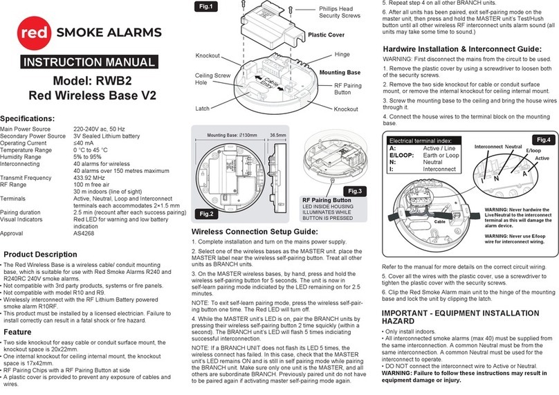
RED RWB2 instruction manual

Burg Wächter
Burg Wächter BURG protect SMOKE 2050 Assembly and user's manual

Fire-Lite
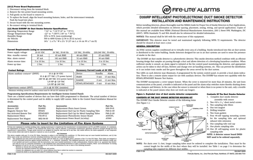
Fire-Lite CP355 Installation and maintenance instructions

Abus
Abus FURM50001 Installation and operating instructions
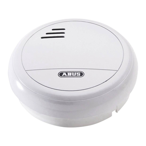
Abus
Abus RM 03 VdS Operating and installation instructions

Fire Pro
Fire Pro FP522V user manual
