Inductosense Wand Echo 45 Instruction Manual

Document: 1.04.04 Rev5
Document: 14.05.19 REV.1
WAND ECHO 45
Installation & User Manual

Document: 1.04.04 Rev5 Document: 1.04.04 Rev5
Disclaimer
Inductosense Ltd does not warrant that theTMS sensors are suited to all environments
and applications. Inductosense Ltd makes no warranty and representation, either
implied or expressed, with respect to the quality, performance, merchantability, or
tness for a particular purpose.
Inductosense Ltd has made every effort to ensure that manual is accurate and disclaims
liability for any inaccuracies or omissions that may have occurred. Information in this
manual is subject to change without notice and does not represent a commitment
on the part of Inductosense Ltd. Inductosense Ltd assumes no responsibility for any
inaccuracies that may be contained in this manual and makes no commitment to
update or keep current the information in this manual, and reserves the right to make
improvements to this manual at any time without notice. If you nd information in
this manual that is incorrect, misleading, or incomplete, we would appreciate your
comments and suggestions.
No part of this document can be reproduced, transferred, distributed or stored in
any format without prior permission of Inductosense Ltd.
Please contact Inductosense Ltd if you have any queries regarding this manual or the
product.
Inductosense Ltd.
UnitDX, St.Phillips Central, Albert Road, Bristol, U.K.
How to use this manual
This manual addresses best practise and the recommended approach for ECHO
installation.
This booklet includes:
INTRODUCTION Page 3
EQUIPMENT Page 4
INSTALLATION Page 5
Other instruction manuals in the WAND series:
WAND IDM Software Manual
WAND Data Collection User Manual
WAND Sensor Installation Manual
1 2

Document: 1.04.04 Rev5 Document: 1.04.04 Rev5
INTRODUCTION
The WAND ECHO is an extension
coil designed to allow measurement of
sensors under insulation and cladding.
The round sensing end is applied
directly over a pre-installed sensor and
the square measurement end is applied
on top of cladding for measurement
with the standard WAND probe.
An ECHO is usually associated with
a number, eg ECHO 45. where the
number relates to the cable length of
the device.
EQUIPMENT
The list below details all items required for installation of the WAND ECHO.
- Pre-installed/coated WAND sensor
- WAND ECHO
- Gloves (size L and XL)
- Sand paper (grit 240)
- IPA wipes
3 4
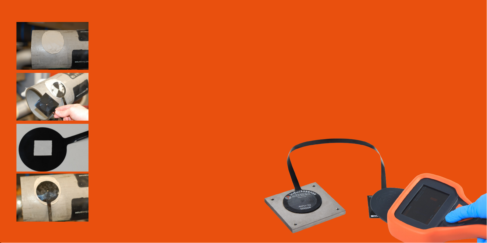
45cm
Figure 1 (Right and below):The WAND ECHO 45 pictured,
allows the activation point for WAND sensors to be offset
to accommodate bulky insulation or cladding layers or to
simplify monitoring of hard to access locations.
- Permanent marker
- Adhesive tab
- UHB Tape rectangle x 2
- WAND measurement probe
Document: 1.04.04 Rev5 Document: 1.04.04 Rev5
56
INSTALLATION
1. Locate the sensor over which the ECHO is
to be installed, removing any covering insulation
and cladding to expose the surface of the sensor.
Lightly sand the coating and surrounding area
of the sensor and clean thoroughly with the
supplied IPA wipe.
2. Position the ECHO sensing (round) end over
the sensor, use the WAND probe to determine
the location with greatest signal strength. Mark
this position using a marker pen.
3. Before proceeding to adhere the ECHO
sensor in place, check that the marked position
allows for the ECHO cable to exit any covering
cladding/insulation with minimal twisting and
bending.
4. Apply an adhesive tab to the reverse side of
the ECHO sensing end, peel off the backing and
adhere over the sensor, following the marker
lines.
5. Remove the paper backing from the UHB tape disc and apply over the
top of the ECHO sensor. Press rmly to ensure that a good seal is formed
around the ECHO.
6. Select an appropriate location for the ECHO measurement (square) end,
ensuring that there is enough slack in the cable to allow repositioning of any
insulation or cladding on top.
7. Lightly sand and clean the selected location to remove any surface
contamination which may hinder adhesion.
8. Remove backing paper from the ECHO measurement end and adhere in
the selected location.
9. Apply the second UHB tape rectangle over the top of the square end of
the ECHO.
10. Take a test measurement using the WAND data collector to ensure
good signal strength and RFID reading.

Document: 1.04.04 Rev5 Document: 1.04.04 Rev5
7 8
Figure 2: The ECHO 45 in the process of being installed. In this case
the ECHO is being used to extend the WAND reading location to the
outside of a thick layer of insulation and to offer a more convenient
access point. Using the ECHO in this way can signiicantly reduce the
risk of secondary corrosion under insulation
Figure 3: ECHO fully installed with the metal clad
inslulation layer reapplied. Note the RFID tag co-located
with the ECHO activation pad.
Installing an RFID
The RFID must be applied relative to
the ECHO measurement coil in an
orientation which allows detection by
the WAND probe.
In order to ensure detection, position
the RFID tag up against one edge of
the ECHO measurement coil, so that
it is below the coil when read using
the WAND probe, as shown in g.3.
Refer to WAND Sensor Installation
Manual for instructions on RFID
installation
Table of contents


