Industrial Fiber Optics IF 535 Manual

In d u s t r I a l FI b e r Op t I c s
Model Number:
IF 535
Modern Laser
Optics Kit
Instruction Guide

*
Copyright © 2012
Previous printings 2000 and 2009
by Industrial Fiber Optics, Inc.
Revision C
Printed in the United States of America
* * *
All rights reserved. No part of this publication may be reproduced,
stored in a retrieval system, or transmitted in any form or by any means
(electronic, mechanical, photocopying, recording, or otherwise)
without prior written permission from Industrial Fiber Optics.
* * * * *
The procedures in this manual are written for use with Industrial Fiber Optics helium
neon and diode lasers. You may need to adjust the steps slightly to accommodate other
manufacturers’ lasers.

– i –
TABLE OF CONTENTS
LASER CLASSIFICATIONS............................................................ ii
INTRODUCTION.....…...................................................…..……..… 1
EQUIPMENT NEEDED…………..................................……....……. 2
Kit Components......................................................................... 2
SETUP…………...........................................................……....…….. 3
OPTICS MOUNTS…...............................……................................. 4
Broad Beam (violet)................................................................... 4
Arc Beam (bronze).................................................................... 4
Diverging (red)........................................................................... 5
Double-slit (turquoise)................................................................ 5
Multiple-slit (blue)...................................................................... 6
Crosshair (silver)........................................................................ 6
Grid (green)........................................................................... 7
Polarization (black).................................................................... 7
Fiber Optics (gold)..................................................................... 8
GEOMETRIC OPTICS..................................................................... 9
DIFFRACTIVE OPTICS.................................................................... 10
POLARIZATION............................................................................... 11
OPTICAL FIBER THEORY.............................................................. 12
WARRANTY..................................................................................... 14
SHIPMENT DAMAGE CLAIMS....................................................... 15

– ii –
Class Description
IA laser or laser system which does not present a hazard to skin
or eyes for any wavelength or exposure time. Exposure varies
with wavelength. For ultraviolet, 2 to 4 µm exposures is less than
from 8 nW to 8 µW. Visible light exposure varies from 4 µW to 200
µW, and for near-IR, the exposure is < 200 µW. Consult CDRH
regulations for specic information.
II Any visible laser with an output less than 1 mW of power. Warning
label requirements — yellow caution label stating maximum output
of 1 mW. Generally used as classroom lab lasers, supermarket
scanners and laser pointers
IIIa Any visible laser with an output over 1 mW of power with a
maximum output of 5 mW of power. Warning label requirements
— red danger label stating maximum output of 5 mW. Also used
as classroom lab lasers, in holography, laser pointers, leveling
instruments, measuring devices and alignment equipment.
IIIb Any laser with an output over 5 mW of power with a maximum
output of 500 mW of power and all invisible lasers with an output
up to 400 mW. Warning label requirements — red danger label
stating maximum output. These lasers also require a key switch
for operation and a 3.5-second delay when the laser is turned on.
Used in many of the same applications as the Class IIIa when
more power is required.
IV Any laser with an output over 500 mW of power. Warning label
requirements — red danger label stating maximum output. These
lasers are primarily used in industrial applications such as tooling,
machining, cutting and welding. Most medical laser applications
also require these high-powered lasers.
LASER CLASSIFICATIONS
All manufacturers of lasers used in the United States must conform to regulations
administered by the Center for Devices and Radiological Health (CDRH), a branch of the
U.S. Department of Health and Human Services. CDRH categorizes lasers as follows:

– 1 –
INTRODUCTION
Welcome to the exciting world of modern optics. The kit you are going to use
contains a variety of optical elements. These elements will allow you to begin to
explore the many aspects of modern optical technology. All of the optics mounts
are easy to use and from each you will learn about another aspect of modern
optic technology. All you must provide is the laser.
This manual is an instruction guide and technical reference for Industrial
Fiber Optics’ Modern Laser Optic Kit. The manual contains step-by-step
instructions to guide you in setting up the laser and use of each optical element.
Each optical mount is also discussed in detail, including visual effects, how the
optical element created a particular effect and practical real-world applications.
With the nine optical mounts found in this kit you will experiment with geometric
and diffraction optics, polarization and one of the latest developing optical
technologies — ber optics. At the end of the manual are four reference sections
to help explain individual optical technologies.
Industrial Fiber Optics makes every effort to incorporate state-of-the-art
technology, highest quality and dependability in its products. We constantly
explore new ideas and products to best serve the rapidly expanding needs of
industry and education. We encourage comments that you may have about our
products, and we welcome the opportunity to discuss new ideas that may better
serve your needs. For more information about our company and products refer to
http//www.i-beroptics.com on the Internet.
Thank you for selecting this Industrial Fiber Optics product. We hope it
meets your expectations and provides many hours of productive activity.
Sincerely,
The Industrial Fiber Optics Team

– 2 –
EQUIPMENT NEEDED
• ModernLaserOpticsKit.
• Heliumneonordiodelaserproducingavisiblelightemissionwitha3/4
inch×32−threadopticalmount(foundonmostlow-powerededucational
lasers.)
• Wallorotheratverticalsurface.
* Any laser which produces visible light is suitable for use with this optics kit. This includes
helium neon and diode lasers. The displays produced by diode lasers for the turquoise and
blue optic mounts will not be quite as sharp as those created by a helium neon laser, but
will be entirely adequate.
Kit Components
Your optics kit contains this manual, a length of clear optical ber and the follow-
ing colored, threaded optics mounts:
Violet Bronze Silver
Turquoise Blue Black
Green Red Gold

–3–
SETUP
1. Review the laser safety rules on the back cover of this manual.
2. Findatableapproximately600×900cm(2×3feet)orlargerinsizefrom
whichthelasercanbepointedtoaverticalwallordullreectingsurface.
The distance from the laser to the surface should be approximately three
meters (10 feet).
3. Pushthelaserbeamstophandledownwardtoitsclosedpositionandmake
sureitsON/OFFswitch(SW)isintheOFFposition.(Thepushbutton
should be in its extended position.)
4. Plugthe110VAC-to-DCpoweradapter(providedwiththelaser)intoan
AC wall outlet. Insert the cord from the power adapter into the power jack
(PWR)locatedontherearofthelaser.
5. DepresstheON/OFFswitch(SW)onthecontrolpanelofthelaseruntilit
clicks into the ON position. (The switch should be slightly depressed.) The
pilotlight(greenLED)justtorightoftheON/OFFswitchshouldnowbe
lit, showing that the laser is on.
6. Push the laser’s beam stop handle upward, to its open position.
7. Observe the red beam striking the wall, or other surface, in the direction
thatthelaserispointed.Keepthelaserpointedinthisdirectionduringall
experiments.
8. Push the laser’s beam stop handle downward, to its closed position.
9. The next section contains descriptions of each of the nine optic mounts.
Wesuggestthatyouinstalltheopticmountsandobservetheresulting
laser beam patterns in the order they are listed in the section titled “Optics
Mounts.”
10. You will gently thread the colored optic mounts in your kit into the laser’s
opticsmount.Note:Makesurethebeamstophandleisinthedownward
or closed position when attaching and removing each threaded optic
mount.
11. Dim the room lights
and observe the unique
pattern on the wall that
each of the optic mounts
produces.Note:Each
threaded mount may need
a slight turning adjustment
to produce optimum visual
patterns.

–4–
12. Turn on the room lights, then push the beam stop handle on the laser
down to its closed position. Remove the threaded optic mount and place it
back in the optics kit. Continue with the next optic mount using the same
procedure, starting with steps 10 and 11.
13. Whenyouhavenishedexperimentingwiththeopticsmounts,turnoff
the laser, disconnect its power cord at both ends and put away all the
materials used in this experiment.
OPTICS MOUNTS
Broad Beam (violet)
This optic mount, when installed in a laser,
positions a cylindrical rod or lens in the path
of the laser beam. The laser beam passing
through the cylindrical lens will be spread in
one (dimensional) plane to produce a broad line,
as shown in the picture to the right. Screw the
violet optic mount into the laser and observe
the resulting laser pattern. Rotate the threaded
optical mount and observe the rotation of the
laser line. Notice that the cylindrical lens in the
mount is at a right angle to the line on the wall. One application of using a laser and lens in
this fashion is aligning items according to similar heights or positions.
Arc Beam (bronze)
This optic mount is similar to the previous
mount except the cylindrical rod has been placed
at a complex angle to the laser’s light beam
instead of being at a right angle. This complex
angle causes the laser beam to intercept the
rod at a continuously varying angle, which will
produce an interesting visual result. Attach the
bronze optical mount and observe the resulting
pattern for yourself.
The pattern you should see with this optic mount is an arc or segment of a circle. Rotate
the mount and observe the different visual effects, with the position of the laser beam
changing in response to the changing position of the lens.

– 5 –
Diverging (red)
In some applications it is desirable to have
alaserbeamdiameterlargerthanthe1-to-2
mm beam size typical of the laser you are
now using. One application requiring a larger
lightbeamistheexposureofholographiclm,
where we would want to illuminate an entire
object, rather than just a small portion of that object. One way to increase the size of a laser
beamisshownbytheopticscongurationtotheright.Thepairofopticallensesusedin
thismanneriscommonlycalleda“beamexpander.”
Screw the diverging (red) optic mount into the laser. Observe the large dispersed beam on
the wall or screen. The diverging laser beam in this optic mount was created with a short
length of special glass rod. The rod intercepts the laser beam and breaks it into many small
diverging beams.
This seemingly simple pattern on the wall can
beusedtotestyoureyes!Lookdirectlyatthe
spot on the wall where the laser beam strikes
until you see a speckled light pattern consisting
of many small dots. You may have to look
carefullytoseethetinydots.Moveyourhead
very slowly from side to side while observing the
spot.Ifyouare“farsighted”orifyoureyesare
normal, the small spots will appear to move in
thesamedirectionasyourhead.Ifyouare“nearsighted,”thespotswillappeartomovein
a direction opposite that of your head movement.
Another experiment you can perform is to observe the effects of evaporation. Place a small
amount of isopropyl (rubbing) alcohol on the end of the glass rod with a cotton swab.
Whenthealcoholevaporatesyouwillseethelaserspotmove.
Double-slit (turquoise)
The optical mounts you have used so far have
had geometric optical elements to focus or
change the direction of the laser beam. (See
page 9 for a more detailed explanation of
geometric optic principles.) Another technique
that scientists and engineers often use to create
special effects or manipulate light is diffraction.
To learn more about diffraction let’s begin by
passing the laser beam through two narrow slots.
Attach the turquoise optic mount to the laser by following the procedures previously
described and observe the pattern. The laser light pattern should appear as a series of dash
1306.eps
Light rays

– 6 –
lines or slots spaced along one line. The center slots should be much brighter, while the
outer dash lines diminish in intensity. Rotate the optic mount in the laser chassis.
The pattern produced on the wall is the result of the laser beam being broken down into
two separate and independent beams by the optic mount. From each slot a beam travels
outward and diverges as it moves from its slot toward the wall. The beams recombine
at the wall and — because they are precisely the same wavelength — they create an
interference pattern of alternating bright and dark spots. (For more details about diffraction,
see page 10 of this manual.)
Multiple-slit (blue)
A more dramatic visual effect results from
diffraction wave interference if the number of
slots is increased from two to a continuous array.
The laser light pattern will appear similar to the
one produced by the previous optical mount,
only this time the dots will be much brighter
and the outer dots will diminish in intensity. The
spacing between each dot will also increase.
Attach the blue optic mount to the laser. The pattern that you observe on the wall should
be similar to the picture shown at the right. The individual light spots should be much
more intense than with the previous optic mount and more of a round spot than dash. This
increaseddenitioniscausedbyagreaternumberofslotscontributingtothediffraction
light pattern.
Crosshair (silver)
Thisopticalmountwilloffertherstdemonstrationofhowthesimplediffractiveeffect
can be expanded to create very useful light patterns. Attach the silver optic mount to the
laser. This diffraction optic lens creates one
perpendicular line and one horizontal line that
intersect to form open quadrants as shown. The
intersection of the two lines forms a brighter
image (dot) at the point where they cross and
can be used in various alignment or positioning
applications. If a precise spot needs to be
chosen or analyzed, a crosshair pattern creates
a reference area and makes positioning easier
toattainthanwhenusingonlyadot.Inthemedicaleldthishelpspinpointanareaofthe
body that needs radiation treatment for cancer. Technicians use this directed pattern for
X-raylmplacementonspecicbodyparts.Otherapplicableeldsarethemilitary,science,
industry (for positioning in manufacturing) and in construction.

– 7 –
Grid (green)
The concepts used in creating the crosshair
pattern can be further expanded to generate
more complex images. Patterns such as these
would be impossible with conventional optical
elements, as you will see next.
Thread the green optic mount in the laser
optics mount. Observe the resulting pattern.
This diffractive optic element creates one large
outer square with 16 inside symmetrical squares
interlocking to form a grid. As with the silver mount, grid patterns such as these can be
used in many areas including industry, for exact positioning of tools in manufacturing,
creating map quadrants of various sizes, military target positioning and hospital use for
X-rayplacement.Canyouthinkofotherpossibleuses?
Polarization (black)
An often overlooked and misunderstood property of light waves is polarization. For a
quickoverviewofpolarizationandwaves,gotopage11.Wewillhelpyouvisualize
polarization and its effects on light with this mount. The laser you will likely have used in
theseexperimentsthusfarisaheliumneonordiodelaser.Helium-neonlaserscanproduce
light that is random, uniformly or linearly polarized. Diode lasers always produce linearly
polarized light. The black optics mount in this kit has a linear polarizer attached to its rear
surface which will aid in determining the type of polarized light your laser produces. Install
the black optic mount in the laser. Observe the optical beam pattern on the wall for about
60 seconds. If the beam varies in brightness your laser is randomly polarized.
If the spot is constant, your laser is either linearly or uniformly polarized. To determine
which,rotatetheblackopticmountacomplete360degrees.Iftworotationalpositions
produce an output beam that is very, very dim, your laser is linearly polarized. If the
brightness of the laser beam does not change during rotation, your laser is uniformly
polarizedandproduceslightofalllinearpolarizationangles.Whattypeofpolarizationdoes
yourlaserproduce?
The previous diffractive optical mounts produced images with straight lines or dots.
However this is not the limiting case. Diffraction optics can be used to create arcs,
circles, diagonal lines, etc., to provide entertaining laser light shows or advertising
displays as well.

– 8 –
Rotate the black optic mount
in the laser so the laser beam
is clearly visible. In your optics
kitndanotherpieceoflinear
polarizer material, a thin piece
of gray plastic approximately 25
× 25 mm (1 × 1 inch). Hold the
second polarizer with your hand
perpendicular to the laser beam
so the laser beam passes through the polarizer. Now rotate the polarizer in your hand while
observing the laser beam on the wall. At some point the intensity of the laser beam should
diminish until it almost disappears. This is the point at which the linear polarizer plane
lmsareatrightanglestoeachother.
Polarizingltersareusedinsunglasses,photographyandmanyotherapplications.When
polarizinglightpanelsareplacedinofcebuildingstheycanreducelightinglevelsand
still produce better viewing conditions. This both conserves energy and creates more
comfortable working conditions. Polarized sunglasses reduce glare from water because the
majorityoflightreectingfromwaterisinoneplane.
Fiber Optics (gold)
Thegoldopticmountholdstheopticalbercablefoundinyourkit.Identifytheoptical
bercableanditsendwhichhasasmallblackplug,theninserttheplugintotheholein
the gold optic mount. Hold the cable straight and observe the laser light coming from the
berendbyholdingyourhandorapieceofpaperneartheberend.(Donotlookdirectly
attheberend.Thislaserenergystillcanbeharmful.)Nowloopthecablesothelight
must travel in circles to exit, and again observe the light coming from the end of the optical
ber.Noticethatnomatterwhatshapetheberforms,lightcontinuestotravelthrough
thecable.Howdidthisoccur?Formoreinformationonthephysicsofopticalberandits
light-carryingcapabilitiesseepage12.
1305.eps

– 9 –
GEOMETRIC OPTICS
Geometricopticalelementsarethosethatbendorreectlightbasedongeometryprinciples
andphysicslawspertainingtorefraction/reection.Geometricopticalelementsinclude
most common lenses or mirrors as found in microscopes, telescopes, binoculars and
eyeglasses. Fundamental to this concept is all optical materials having a property called
refractiveindex(n).Amaterial’srefractiveindexisdenedastheratioofthespeedoflight
in a vacuum, to the speed of light in the material.
The second fundamental property in
geometric optics is prescribing that
light travels in straight lines through
all optically transparent materials.
However, when light travels from
one material to another, something
different happens. If the refractive
index of the two materials differs, light is bent as it passes through the boundary—for
example, passing from air into glass, as shown above. The amount of bending depends
on the refractive indices of the two materials and the angle (geometry) of the incident ray
striking the boundary between the two mediums. The angles of incidence and refraction
are measured from a line perpendicular to the surface. The mathematical relationship
betweentheincidentraysandtherefractedrayswasrstpredictedbyascientistnamed
WillebrordSnell(1591-1626).Snell’sLawdescribesthebendingoflightpassingthrougha
boundarybetweentwoopticallyconductivematerials.Mathematically,Snell’sLawstates:
wheren’andn”aretherefractiveindicesoftheinitialandsecondarymaterial,respectively,
while and are the angles of incidence and refraction, respectively.
Expandingthisconcepttoagroupofparallellightraystravelingthroughairandstriking
a piece of glass with a curved polished surface it is obvious that the light rays would
bend. (Glass has a refractive index of 1.5 and air 1.0.) The amount of bending that occurs
depends on the geometry at which the light rays strike the curved surface as shown to the
right. This bending of light rays causes optical
lenses to focus light, as shown at right.
A mirror is an optical lens whose surface
iscoveredwithareectivecoatingsuchas
aluminumorgold.Lightraysstrikingamirrored
surfacereectatanangleequaltothe
incident angle.
1303.eps
Θ
2
Medium 1: air (n 1)
Incident ray
Θ1
Medium 2: water (n2)
Refracted
ray
Normal line Reflected ray
1274.eps
n' sin q'=n" sinq"
q'
q"

– 10 –
DIFFRACTIVE OPTICS
Inthesectionongeometricoptics,wedenedlight
as traveling only in straight lines. That is true—but
primarily in cases where the wavelength of light is
many times smaller than the lens, mirrors, or other
surfaces it encounters. This characteristic changes as
objects become smaller and approach the same size as
thewavelengthoflight.Whenwavespassthrougha
slit as shown at the right, we might think they would
continueontheirwayinstraightlines.Notso.When
waves pass through a small slit similar in size to their
wavelength, they diffract or bend, as shown in the
illustration. The amount of bending depends on the
size of the wavelength of light compared to the size of
the opening. You may have observed how incoming
ocean waves react when they encounter a breakwater or reef. They bend, then spread out.
If wave diffraction were not a reality you could not hear someone talking from across the
room unless they were directly facing you.
Interference is another wave effect created when two or more
identicalwavesencountereachotherasshowninthegure
at the left. In some areas the crests of the two waves combine
easily. But in other cases, the wave crests and troughs meet
in a destructive collision so they instantaneously cancel each
otherandnothingremains.Thecombinationconstruction/
destruction pattern was produced when you used the
turquoise mount. Interference occurs only when wavelengths
are identical, as when produced by a laser. You will never
see interference caused by light from an incandescent or
uorescentlightbulbbecausewavelengthsfromthosesources
are not identical.
Aswithmostscienticprinciples,fundamentalconceptsinthisareacanbeexpanded
andrened.Withtheblueopticsmountthisisexactlywhatwasdone.Twoslotswere
expanded to an array of slots. The resulting beam pattern became multiple small dots,
ratherthanaseriesofdashes.Ifwewerefeelingcreative,ournextstepmightbeguring
out a way to pass a beam of light through an optical pattern so a more artistic or complex
pattern is created, using a combination of diffraction and interference. In fact, these two
scienticprinciplesareexactlywhatweusedinthesilver,greenandgoldmounts.
1268.eps
1302.eps

– 11 –
POLARIZATION
All waves possess one of two different types of motion. Sound waves are compressional
motion(likecompressing,thenreleasingaspring).Lightwaves,however,aretransverse.
Tovisualizetransversewaves,imagineholdingoneendofa10-foot-longropeinonehand.
The other end of the rope is fastened to a wall, and you are pulling it tight, so it extends
inahorizontalline.Nowmovethathandup/down,right/leftandcircularinrandom
patterns.Withthesemotionsyouarecreatingavisualmodelofatransverselightwave.
Energy,orlight,beginsatyourhandandendsupatthewall.Allenergyorwavesthatyou
createdintheropeareunpolarizedbecausethereisnodenedpatternormotion.Sunlight
is unpolarized, as is light from most light sources except lasers.
Conversely, a linearly polarized
wave travels in a known and
nonvarying pattern, as if you
weretomovetheropeonlyup/
down. Unpolarized waves can
belteredintopolarizedwavesifweusespecialmaterialswithslotsorgratingsinthem.
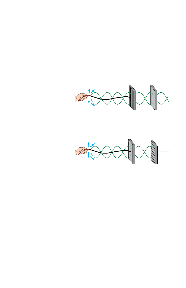
Imagine the rope passing through a grating with only vertical slots, as shown above. The
slot prevents sideways motion, but freely allows the vertical components of vibration
to pass.
Placing a second vertical grating
behind, and aligned with, the
rstwillstillallowthevibrations
to pass through both sets of slots
freely. However, if we turn the
secondgratingtoahorizontalposition,noneoftheverticallight/wavesexitingtherst
grating will pass through or be transmitted by the second grating.
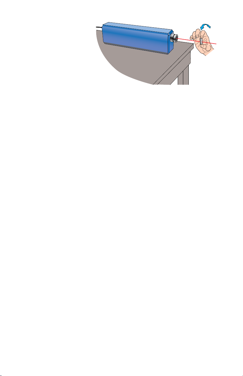
Thepolarizinglterinyouropticskitactslikethegratingsdescribedabove.Imbedded
inside the plastic are molecules that allow only light waves of a certain polarization to pass
through.Whenunpolarizedlightpassesthroughalinearpolarizinglter,itemergesas
polarizedlightvibrationsinasingleplane—althoughwithone-halftheintensity.
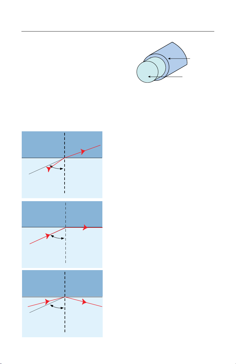
Unpolarizedlightcanalsoundergopolarizationbyreection.Non-metallicsurfaces
suchasasphaltroads,snoweldsandwaterreectlightwithalargeconcentrationof
vibrations(whichwecommonlycall“glare”)inaplaneparalleltothereectingsurface.
Lightreectedoffalakeispolarizedmostlyinadirectionparalleltothewater’ssurface.
Glareoftenpreventsshermenfromseeingshinthewaterbelow.Savvyanglersknow
that using special sunglasses (containing lenses with a proper polarization axis) reduces
glare,andtheycaneasilyseeshandotherunderwaterobjects.Polarizationhasawealth
ofotherapplicationsbesidesitsuseinglare-reducingsunglasses.Inindustry,polarizing
equipment is used to indicate stress in transparent plastics. Polarization also is used in the
entertainmentindustrytoproduceandshow3-Dlmsandvideotapes.
1301.eps
1300.eps

– 12 –
OPTICAL FIBER THEORY
Fiber optics is the most rapidly growing portion
of optics study in the world. It has grown so
dramatically that some people may not think of it as
evenbeingpartoftheopticseld.Intermsofdata
communicationstheycouldberight,becauseber
optic communications utilizes electronic and laser
technology,inadditiontoopticalber.
Theillustrationabovedepictstheconstructionofbasiccommunicationopticalber,with
concentric layers of materials called the core and cladding. These materials are bonded
to each and are always composed of different materials because they must have different
refractiveindexes.Withthewaveguidescontainedinthiskitthecladdinglayerisair.The
acrylic bars are the cores.
Inopticalbers,theoutermaterialalwayshas
a lower refractive index than the inner layer.
Visualizealightray—travelingataspecic
angle — as it strikes the boundary between
higher and lower refractive index materials. As
the light ray enters the lower refractive index
material, it bends away at an increased angle,
as shown. If the entry angle of the light ray
increases, eventually the exiting ray will be
parallel to the horizontal boundary between the
materials. This entry angle is called the critical
angle (qc). Any further increases in the angle of
the incident (entry) ray will actually cause the
lightraystoreectbackintothematerialwith
largerrefractiveindex—thecore.Thisreection
iscommonlycalled“totalinternalreection”and
is the basis for the theory of how light travels
throughopticalber.Becausethecladding
layersurroundsthecore,thelightisconned
to two dimensions and travels lengthwise (also
“rebounding”fromsidetoside)fromoneendof
thebertotheother.
Totalinternalreectionisessentially“loss-less”
reection.Nolightislostateachsuccessive
reectionwithintheber,whichmakesthis
concept very suitable for transmitting light over
long distances. Any minor loss of light in optical
beriscausedprimarilybyimpuritiesinthe
core material.
1304
Core
Cladding
Cladding
Core
R3
θc
R3'
1350.eps
Cladding
Core
R2
θc
R2"
Cladding
Core
R1
θc
R1"

–13–
Commerciallyavailableopticalberisusuallymadefromglassorplastic.Opticalber
can carry many times more information — faster and over longer distances — than
conventional copper wire, and it is far less vulnerable to electromagnetic interference.
Otheradvantagesofberopticsincludeeaseofinstallationandtheabilitytotransmitdata
withextremelylowerrorrates.Opticalberalsodoesnot“attract”lightningstrikes,since
it is not electrically conductive.
Table 1. Refractive indices of some common materials.
MATERIAL VALUE
Air 1.00029
Water 1.33
Glass 1.4 - 1.8
Silicon 3.5
Acrylic 1.49
Diamond 2.0

–14–
WARRANTY
Industrial Fiber Optics products are warranted against defects in materials and
workmanship for 90 days. The warranty will be voided if the components have been
damaged or mishandled by the buyer, including as a result of dropping or scratching of
optical surfaces.
Industrial Fiber Optics’ warranty liability is limited to repair or replacement of any defective
unit at the company’s facilities, and does not include attendant or consequential damages.
Repair or replacement may be made only after failure analysis at the factory. Authorized
warranty repairs are made at no charge, and are guaranteed for the balance of the original
warranty.
Industrial Fiber Optics will pay the return freight and insurance charges for warranty repair
within the continental United States by United Parcel Service or Parcel Post. Any other
delivery means must be paid for by the customer.
The costs of return shipments for products no longer under warranty must be paid by the
customer. If an item is not under warranty, repairs will not be undertaken until the cost of
such repairs has been approved, in writing, by the customer. Typical repair costs range from
$10-$50andusuallyrequirelessthanoneweektocomplete.
Whenreturningitemsforanalysisandpossiblerepair,pleasedothefollowing:
• Inaletter,describetheproblem,persontocontact,phonenumberand
return address.
• Packthelaser,poweradapter,manualandlettercarefullyinastrongbox
with adequate packing material, to prevent damage in shipment.
• Shipthepackageto:
In d u s t r I a l FI b e r Op t I c s
1725 We s t 1s t st r e e t
te m p e , AZ 85281-7622
UsA

– 15 –
SHIPMENT DAMAGE CLAIMS
If damage to an Industrial Fiber Optics product should occur during shipping, it is
imperative that it be reported immediately, both to the carrier and the distributor or
salespersonfromwhomtheitemwaspurchased.DONOTCONTACTINDUSTRIAL
FIBEROPTICS.
Timeisoftheessencebecausedamageclaimssubmittedmorethanvedaysafterdelivery
may not be honored. If shipping damage has occurred during shipment, please do the
following:
• Makeanoteofthecarriercompany;thenameofthecarrieremployee;
thedate;andthetimeofthedelivery.
• Keepallpackingmaterial.
• Inwriting,describethenatureofdamagetotheproduct.
• Notifythecarrierimmediatelyofanydamagedproduct.
• Notifythedistributorfromwhomthepurchasewasmade.

12 0140
Rules for Laser Safety
• Lasersproduceaveryintensebeamoflight.Treatthemwithrespect.Most
educationallasershaveanoutputoflessthan3milliwatts,andwillnotharm
the skin.
• Neverlookintothelaseraperturewhilethelaseristurnedon!PERMANENT
EYEDAMAGECOULDRESULT.
• Neverstareintotheoncomingbeam.Neverusemagniers(suchasbinocularsor
telescopes) to look at the beam as it travels – or when it strikes a surface.
•Never point a laser at anyone’s eyes or face, no matter how far away they are.
• Whenusingalaserintheclassroomorlaboratory,alwaysuseabeamstopor
project the beam to areas which people won’t enter or pass through.
•Never leave a laser unattended while it is turned on – and always unplug it when
it’s not actually being used.
•Remove all shiny objects from the area in which you will be working. This
includesrings,watches,metalbands,toolsandglass.Reectionsfromthebeam
can be nearly as intense as the beam itself.
• Neverdisassembleortrytoadjustthelaser’sinternalcomponents.Electricshock
could result.
Table of contents
Other Industrial Fiber Optics Measuring Instrument manuals

Industrial Fiber Optics
Industrial Fiber Optics ML 801 User manual

Industrial Fiber Optics
Industrial Fiber Optics 45-545A User manual

Industrial Fiber Optics
Industrial Fiber Optics IF-RL05 User manual

Industrial Fiber Optics
Industrial Fiber Optics IF User manual

Industrial Fiber Optics
Industrial Fiber Optics ML 800 Series User manual
Popular Measuring Instrument manuals by other brands

Flomotion Systems
Flomotion Systems BE6200 Installation and operation manual

ALTONOVUS
ALTONOVUS NanoRanger instruction manual

Thommen
Thommen CM30 Installation and operating manual

EDI
EDI ED400D-E-111-4D-N4-SR1 product manual

Tintometer
Tintometer Lovibond MD100 instruction manual

Agreto
Agreto AgriCounter Drive user manual