Changzhou Tonghui Electronic TH2821B Installation manual

OPERATION MANUAL
English
February 2006
1
st
Edition Rev 1.0.0
© Copyright 2006 Changzhou Tonghui Electronic Co. Ltd.
All rights reserved.
TH2821B
Portable LCR Meter

TH2821B OPERATION MANUAL
2
Contents
Contents...........................................................2
How to Contact UsError! Bookmark not
defined.
Incoming Inspection ....................................3
Notes on Use ..............................................4
Warranty: ...................................................5
Chapter 1 Overview...........................................7
1.1 Introduction..........................................7
1.2 Main Functions ......................................7
1.3 Speci ications........................................8
1.4 Environment Requirements................... 10
Chapter 2 Panel Illustration ............................. 11
2.1 LCD Display Illustration ........................ 11
2.2 Keyboard Illustration ........................... 13
Chapter 3 Operation........................................ 14
3.1 Power on ............................................ 14
3.2 How to operate ................................... 15
3.2.1 Key Functions ............................ 15
3.3 Battery Replacement ........................... 21
3.4 Clearing Instruction ............................. 22
Appendix ........................................................ 23

TH2821B OPERATION MANUAL
3
Incoming Inspection
Inspect the shipping container or damage. The contents o
the shipment should be listed as ollows. I the contents are
incomplete, i there is damage or de ect, please contact
our company or your nearest Sales and Service O ice.
Accessories
TH26028 DC Power Adapter 1
TH26027 4 terminal Kelvin test clip leads 1

TH2821B OPERATION MANUAL
4
1604A 9V battery 1
User Manual 1
Options
TH26029 SMD component test ixture
Notes on Use
This meter is only or indoor use.
Turn o the TH2821B while switching the power supply
between battery and DC adapter or replacing the
battery.
Although internal circuit protection is provided, DC
voltage or current may damage TH2821B. Be ore you
measure a capacitor, be sure the capacitor is ully

TH2821B OPERATION MANUAL
5
discharged.
Take out the battery when the meter is not in use or
more than 3 months.
A single standard 9V battery can be used or the power
supply. TH2821B will not work normally when battery
voltage is less than 6V.
The 12V AC to DC adaptor is recommended to be used
or TH2821B power supply.
Per orm Open and Short corrections or accurate
measurement especially when test ixture is changed.
The unctions locked with password are not accessible
by users.
Warranty:
This instrument product is warranted against de ects in
material and workmanship or a period o two years rom
the date o shipment. During the warranty period, Our
company will, at its option, either repair or replace
products which prove to be de ective. For warranty service
or repair, this product must be returned to a service acility

TH2821B OPERATION MANUAL
6
designated by our company.
Warranty limitation
The oregoing warranty shall not apply to de ects resulting
rom improper or inadequate maintenance by Buyer,
Buyer-supplied so tware or inter acing, unauthorized
modi ication or misuse, or improper site preparation or
maintenance.

Chapter 1 Overview
Thank you for purchasing our product. To get the maximum
performance from the instrument please read this manual
first and keep this manual at hand.
1 1 Introduction
TH2821B is a microprocessor-controlled portable meter with
low power consumption. It can measure six basic parameters
they are inductance L capacitance C resistance R
impedance |Z| dissipation factor D and quality factor Q.
TH2821B can fulfill the measurement needs of various
component manufacturers and maintenance technicians.
1 2 Main Functions
1
.
..
.
Test Parameter
L-Q, C-D, R-Q and Z-Q.
2
.
Correction
OPEN: multi- requency correction o open circuit;
SHORT: multi- requency correction o short circuit.
3
.
Display Mode
Direct —— direct measurement value;
4
.
..
.
Range Hold
When measuring a large number o components with
the same nominal value, this unction can e ectively
improve the measuring rate.
5
.
..
.
Equivalent Circuit Mode
Both parallel and series equivalent circuit modes can

TH2821B OPERATION MANUAL
8
be obtained.
6
.
..
.
Data Hold
This unction can be used to reeze the current display
value.
1 3 Specifications
Parameter L-Q, C-D, R-Q and Z-Q
Frequency 100 Hz, 120 Hz and 1 kHz
Accuracy
Basic Accurac
y: 0.3%
Display 5
digits display or both primary and secondary
parameters
100 Hz,120 Hz 1 µH – 9999 H
L
1 kHz 0.1 µH – 999.9 H
100 Hz, 120Hz 1 pF – 9999 µF
C
1kHz 0.1 pF – 999.9 µF
R, |Z| 0.0001 Ω - 999.9 MΩ
D, Q 0.0001 – 9999
Measurem
ent Range
∆% 0.0001% - 9999%
1kHz 0 3 Vrms (1±
±±
±10%)
Test Level
(Range
Auto and
Open
Circuit)
100Hz
120Hz 0 3 Vrms (1±
±±
±15%)
Ranging
Mode Auto and Hold
Equivalent
Circuit Parallel and Series
Display Direct
TH2821B OPERATION MANUAL
9
(Continued)
Correction Open and Short Zeroing
Rate Approx. 3 meas/sec
Terminals 5 terminals
Power Supply 1604 9V battery or DC12V(100 mA) adapter
Low Battery
Indication Approx. 6V
Power
Consumption
Normal: Approx. 30 mA
Auto power-o : Approx. 500 nA
Auto Power
Off time Approx. 30 minutes
Weight Approx. 400 g
Dimensions 200mm(L) × 95mm(W) × 40mm(D)
Table 1-1 Specifications
Note
:
Primary parameter accuracy(A
e
)
C
:
A
e
= 0.3%(1+C
x
/C
max
+C
min
/C
x
)
L
:
A
e
= 0.3% (1+ L
x
/L
max
+ L
min
/L
x
)
Z
:
A
e
= 0.3% (1+ Z
x
/Z
max
+ Z
min
/Z
x
)
R
:
A
e
=
0.3%(1+ R
x
/R
max
+ R
min
/R
x
)

TH2821B OPERATION MANUAL
10
Max and Min values are as follows:
Parameter Range Auto
C
max
80µF/f
C
min
150pF/f
L
max
159H/f
L
min
0.32mH/f
Z
max
1MΩ
Z
min
1.59Ω
Here
:
Z
max
= R
max
; Z
min
= R
min
, Frequency unit: kHz.
Secondary parameter accuracy
D
e
= A
e
/3 when D
x
≤0.1
D
e
= A
e
(1+D
x
)/3
when D
x
>
0.1
Q
e
=
ex
ex
DQ
DQ
×
×
±µ1
when Q
x
·
D
e
<1
1 4 Environment Requirements
1
.
Please do not operate TH2821B under the following
environment conditions as any of them will directly
affect measuring precision or damage the meter:
Please do not operate the instrument in places
where is dusty, vibrant, under direct sunlight, or
where there is corrosive air.
Although TH2821B has been specially designed
for reducing the noise caused by AC power, the
environment with low noise is still recommended.
If this can not be arranged, please make sure to
use power filter for the AC-DC adaptor.
2
.
The TH2821B must be operated under the ollowing
environment conditions:
Temperature: 0°C ~ 40°C,
Humidity: ≤ 90% RH at 40°C.
3
.
Storage Temperature: -25°C ~ 50°C.
TH2821B OPERATION MANUAL
11
Chapter 2 Panel Illustration
2 1 LCD Display Illustration
Figure 2-1 LCD Display

TH2821B OPERATION MANUAL
12
No. Description No. Description
1 Battery Power
Indicator 8 Unit Indicator
2 Remote
Indicator 9 Ranging Mode Indicator
3 Beeper
Indicator 10 Primary Parameter
Display
4 Series/Parallel
Indicator 11 Frequency Indicator
5 Comparator
Indicator 12 Primary Parameter
Indicator
6
Secondary
Parameter
Indicator
13 2
nd
Function Indicator
7
Secondary
Parameter
Display
14 DC Adaptor Power Supply
Indicator
Table 2-1 LCD Description
Others:
DH: Data hold indictor
CAL: Correction unction indictor
MENU: Menu operation indictor
TH2821B OPERATION MANUAL
13
2 2 Keyboard Illustration
Figure 2-2 Keyboard
No Key Function
○
1 POWER Power On/O
○
2 PARA Parameter Selection
○
3 FREQ
Frequency Selection
○
4 CLEAR CLEAR Selection
○
5 RANGE Range Selection
○
6 AUTO Range Auto Selection
○
7 DH Data Hold
○
8 EQU Series/Parallel
Indicator
Table 2-2 Key Description
TH2821B OPERATION MANUAL
14
Chapter 3 Operation
3 1 Power on
1. Press POWER key to turn on TH2821B.
2. The operation system version will be displayed.
3. At last the instrument enters the measurement state.
Figure 4-1 Measurement Display
Measurement display description:
1. Battery Supply 3. Beeper ON
4. Series Circuit 5. Sorting Result: P1
6. Parameter D 7. Secondary parameter
8. Unit 9. Range 0 (Auto)
10. Primary parameter 11. Frequency: 1 kHz
12. Parameter C

TH2821B OPERATION MANUAL
15
3 2 How to operate
3 2 1 Key Functions
1. Parameter Setup
:
Press PARA key to select the ollowing measurement
parameter combinations
:
L-Q, C-D, R-Q and Z-Q.
Units Description:
L µH mH H
C pF nF µF
R/|Z| Ω kΩ MΩ
Table 4-1 Units
|Z| is the absolute value of impedance. Measurement
value of L C or R may be positive or negative. Negative
capacitance value means that the device under test is
actually an inductor; also negative inductance value means
that the device under test is actually a capacitor. In theory
R should be positive constantly under some condition R
may be negative due to over zero correction. Please carry
out correct zero correction.
The maximum number of display digits is 5 but 5-digit is
not always available and 4-digit is displayed sometimes.
The conversion is described in the following description:
From 4-digit to 5-digit:
When the first 2 digit of current value is less than 18.
From 5-digit to 4-digit:
When the first 2 digit of current value is more than 20.
2. Frequency Setup:
Use FREQ key to select the ollowing test requencies in
turn: 100 Hz, 120 Hz and 1 kHz.

TH2821B OPERATION MANUAL
16
3. Range Setup:
RANGE and AUTO keys are used to set the measurement
range. AUTO key toggles ranging mode between “Auto”
and “Hold”. RANGE keys are used to increase or decrease
the measurement range if the current ranging mode is
“Auto” then the ranging mode is changed to “Hold” at the
same time.
Note
:
When ranging mode is set to HOLD the measurement
range is fixed at current range. Overload symbol “-----” will
be displayed if the impedance under test exceeds the
current effective measurement range or display range.
Range
No.
Range
Resistor
Range
Up
Range
Down
0 100kΩ
1 10kΩ
2 1kΩ
3 100Ω
4 20Ω
20kΩ
2kΩ
200Ω
20Ω
18kΩ
1.8kΩ
180Ω
18Ω
Table 4-2 Ranges

TH2821B OPERATION MANUAL
17
Note
:
How to calculate the measurement range
Example: Assume capacitance C=210pF dissipation D=0.0010 and
test frequency f=1 kHz.
Solution:
Ω≈
××××
=≈
+=
−
9.757
1021010001416.32
1
2
1
2
1
9
X
X
X
XX
fC
Z
fCj
RZ
π
π
From the Table 4-2 we can get the correct measurement range is
No. 2.
4. Data Hold
Press DH key to reeze the display, press DH key again to
release.
5. Correction Function
Press CLEAR key to select the second unction,
“SHIFT” will be lighted on the screen.
Press CLEAR key to enter the correction unction, the
ollowing in ormation will be displayed on the screen.
Figure 4-2 Correction Display
Clear (Clear) is displayed in the primary parameter
display area, OpeN (OPEN), Short (Short) or Quit

TH2821B OPERATION MANUAL
18
(Quit) will be displayed in the secondary parameter
display area.
Note
:
OpeN (OPEN), Short (Short) and Quit (Quit) are selected and
displayed automatically by the meter according to the impedance
value o the device under test.
Press any key to cancel the correction operation and
return to the measurement state. Press CLEAR key to
start the correction measurement.
When correction measurement is inished, PASS or FAIL
will be displayed on the screen, see Figure 4-3
Figure 4-3 Open correction Passed
Note
:
1
.
The correction unction must be used or accurate measurement.
The correction unction can eliminate the stray admittance
(capacitance, and inductance) and the residual impedance
(resistance and reactance) induced by test ixture, test leads and
instrument itsel . Per orm the correction operation again i the
measurement conditions are changed such as test ixture and
environment temperature.
2
.
It is recommended to per orm the open and short correction at
the same time.
3
.
During short correction period, FAIL (FAIL) will be displayed in
the secondary parameter display area when short correction is
ailed. Make sure that the measurement contacts are shorted

TH2821B OPERATION MANUAL
19
reliably and per orm the short correction again.
4
.
Th2821B measures the correction data at all requency points and
all measurement ranges. The correction data is stored in the
non-volatile memory. So you don’t have to per orm the correction
again, i the test conditions are not changed.
5
.
Open and short corrections are automatically selected by the
instrument according to the impedance value under test. I there
is a component in the ixture or i there is error with the
instrument, Quit (Quit) will be displayed in the secondary
parameter display area.
6. Equivalent Circuit
Press EQU key to select the Series or Parallel circuit
mode.
Note
:
1
.
The actual C, R and L are not the ideal pure C, R and L. Normally
an actual component can be regarded as the combination o an
ideal resistor and an ideal reactor in series or parallel circuit
mode.
2
.
TH2821B can convert between the two di erent equivalent
circuit modes using the ollowing equations. The measurement
values o the two di erent circuit modes maybe di erent under
di erent quality actor Q (or dissipation actor D).
Capacitance Cp: rom parallel to series
Circuit Mode
:
Cp
Rp
Dissipation
:
QRfC
D
PP
1
2
1==
π
TH2821B OPERATION MANUAL
20
Series
:
)1(
)1(
22
2
DDRR
CDC
PS
PS
+=
+=
Capacitance Cs
:
rom series to parallel
Circuit Mode
:
Cs Rs
Dissipation:
Q
CfRD
SS
1
2==
π
Parallel:
22
2
)1(
)1(1
DDRR
CDC
SP
SP
+=
+=
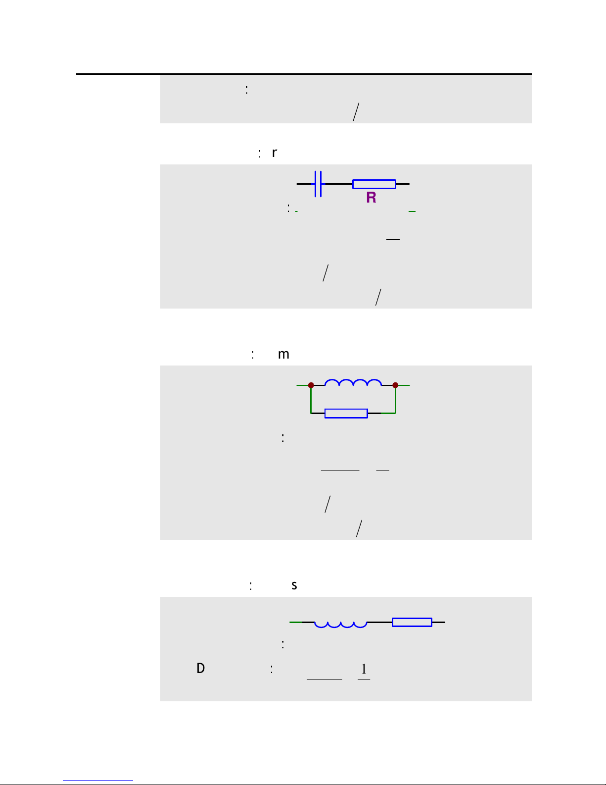
Inductance Lp
:
rom parallel to series
Circuit Mode
:
Lp
Rp
Dissipation:
QR
fL
D
P
P
1
2==
π
Series:
)1(
)1(1
22
2
DDRR
LDL
PS
PS
+=
+=
Inductance Ls
:
rom series to parallel
Circuit Mode
:
Lp Rp
Dissipation
:
QfL
R
D
S
S
1
2==
π
Table of contents
Other Changzhou Tonghui Electronic Measuring Instrument manuals


