Industrial Fiber Optics IF-RL05 User manual

Semiconductor
Diode Laser
Operator’s Manual
IndustrIal FIber OptIcs
Model Number:
IF-RL05
IF-RL08
IF-RL30

*
Copyright © 2023
Previous Printings 2010, 2000, 2001, 2003, 2006
by Industrial Fiber Optics, Inc.
Revision - E
Printed in the United States of America
* * *
All rights reserved. No part of this publication may be reproduced,
stored in a retrieval system, or transmitted in any form or by any means
(electronic, mechanical, photocopying, recording, or otherwise)
without prior written permission from Industrial Fiber Optics.
* * * * *

– i –
INTRODUCTION
This manual provides information about Industrial Fiber Optics lasers model
numbers IF-RL05-635, IF-RL08-635, IF-RL30-635 and IF-RL30-670. It contains
all the information you need to operate these lasers safely and knowledgeably,
even if you are a novice to laser technology. Please read the manual carefully
before operating the laser.
As soon as you receive this laser, inspect it and the shipping container for
damage. If any damage is found, immediately refer to the section of this manual
entitled Shipment Damage Claims.
Industrial Fiber Optics makes every effort to incorporate state-of-the-art
technology, highest quality, and dependability in its products. We constantly
explore new ideas and products to best serve the rapidly expanding needs of
industry and education. We encourage comments that you may have about our
products, and we welcome the opportunity to discuss new ideas that may better
serve your needs. For more information about our company and products refer to
www.i-beroptics.com.
Thank you for selecting this Industrial Fiber Optics product. We hope it
meets your expectations and provides many hours of productive activity.
Sincerely,
The Industrial Fiber Optics Team

– ii –
.

– iii –
TABLE OF CONTENTS
Introduction……………………….................…….....…………..…… i
GENERAL....................................................................................... 1
OPERATIONAL INFORMATION………….......…..…...……............. 3
Electrical………….................................................…..................... 3
Beam Controls............…..........................…...............…............... 6
Specications............…..........................…...............…............... 7
Models and Laser Classications………................…............….... 7
SAFETY…………................…........................….................….......... 8
LASER REGULATIONS................................................................... 9
Certication/Identication.............................................................. 9
Classications............................................................…................ 9
Aperture Labels........................................….................…............. 10
Additional References................................................................... 10
OPERATING PROCEDURES.......................................................... 11
Non-modulation or CW Operation...........................….....….......... 11
Using Laser with Microphone............................…..........….......... 12
TROUBLESHOOTING..............................................….................... 13
SERVICE AND MAINTENANCE...................................................... 14
WARRANTY..................................................….................…........... 15
SHIPMENT DAMAGE CLAIMS....................................................... 16

– iv –
LASER CLASSIFICATIONS
All manufacturers of lasers used in the United States must conform to regulations admin-
istered by the Center for Devices and Radiological Health (CDRH), a branch of the U.S.
Department of Health and Human Services. CDRH categorizes lasers as follows:
Class Description
IA laser or laser system which does not present a hazard to skin
or eyes for any wavelength or exposure time. Exposure varies
with wavelength. For ultraviolet, .2 to .4 µm exposure is less than
from .8 nW to .8 µW. Visible light exposure varies from .4 µW to
200 µW, and for near IR, the exposure is < 200 µw. Consult CDRH
regulations for specic information.
II Any visible laser with an output less than 1 mW of power. Warning
label requirements — yellow caution label stating maximum output
of 1 mW. Generally used as classroom lab lasers, supermarket
scanners and laser pointers.
IIIa Any visible laser with an output over 1 mW of power with a
maximum output of 5 mW of power. Warning label requirements
— red danger label stating maximum output of 5 mW. Also used
as classroom lab lasers, in holography, laser pointers, leveling
instruments, measuring devices and alignment equipment.
IIIb Any laser with an output over 5 mW of power with a maximum
output of 500 mW of power and all invisible lasers with an output
up to 400 mW. Warning label requirements — red danger label
stating maximum output. These lasers also require a key switch
for operation and a 3.5-second delay when the laser is turned
on. Used in many of the same applications as the Class IIIa when
more power is required.
IV Any laser with an output over 500 mW of power. Warning label
requirements — red danger label stating maximum output. These
lasers are primarily used in industrial applications such as tooling,
machining, cutting and welding. Most medical laser applications
also require these high-powered lasers.

– 1 –
GENERAL
Industrial Fiber Optics’ family of diode lasers (whose models vary only in their power and
output wavelength) utilizes the latest technology in miniaturization electronics and laser
science — the same as used in long-distance fiber optic communication networks, CD
players and bar code scanners. The technology incorporates semiconductor laser diodes —
tiny electronic microchips that operate as lasers.
Semiconductor diode devices oer an important alternative to widely known and used
helium-neon-gas (HeNe) lasers. Diode lasers are smaller, more ecient, and oer direct
digital and analog modulation capabilities previously unavailable. Exceptional versatility
makes this semiconductor technology an essential component of modern science, physics
and industrial technology curriculums.
The Industrial Fiber Optics family of lasers oers particular educational value in its ability
to increase and reinforce learning via fascination. They also oer more options for internal
application and types of modulation inputs. With these lasers, students will readily,
enthusiastically learn about physical optics, fiber optics, light propagation, speed of light
theory and measurement, laser communications, and much more!
Table 1. Common abbreviations used in this manual.
Abbr. Long version Scientic Notation
mW milliwatts. 1 x 10⁻³ watts
µW microwatts 1 x 10⁻⁶ watts
nW nanowatts 1 x 10⁻⁹ watts
mm millimeters. 1 x 10⁻³ meters
µm micrometers 1 x 10⁻⁶ meters
nm nanometers 1 x 10⁻⁹ meters

– 2 –– 2 –
OPERATIONAL INFORMATION
Electrical
All electrical controls are located at the rear of the laser chassis. A diagram of the rear view
of the laser appears in Figure 1. Following are descriptions of each item identified in
Figure 1:
1. Power Jack (PWR)
All Industrial Fiber Optics lasers use a standard 2.1 mm DC power input jack to
provide power to the laser. (An ON/OFF switch controls power from the jack to the
electronic circuitry and lasing element.)
Power input to the laser must be applied from a low-voltage DC power source in the
range of 10 to 15 volts, such as supplied with the laser. See Item 9 in this section for
more information about the power adapter.
1
MODEL IF - RL
GAIN
AUDIO
50
INDUSTRIAL FIBER
OPTICS
SW
PWR
DIGITAL
GND
ANALOG
PILOT
MODEL IF - RL
Power adapter
(not shown)
1334.eps
GAIN
1
MODEL IF - RL
MODEL IF - RL
GAIN
GAIN
AUDIO
50
INDUSTRIAL FIBER
OPTICS
SW
PWR
DIGITALGNDANALOG
PILOT
AUDIO
50
INDUSTRIAL FIBER
OPTICS
SW
PWR
PILOT
Figure 1. Rear view of laser showing electrical inputs and controls.

– 3 –
2. Switch (SW)
A push-button switch is located immediately to the right of the 2.1 mm power jack.
It controls power from the 2.1 mm power jack to the electronic circuitry and lasing
element. When the switch is closed it will be slightly depressed, compared to the open
position, when the switch will be fully extended.
3. Pilot light (PILOT)
Just below and left of the Switch is the pilot light. It emits a green light when the
switch is on and power is applied to the electronic circuitry and lasing element
4. Gain control (GAIN)
The gain control feature of this laser makes it the most versatile educational laser
on the market. The Gain control knob is located on the left side of the front panel.
It controls the gain of an internal electrical circuit which amplifies signals from the
microphone (AUDIO) and analog (ANALOG) inputs. This feature is particularly useful
for ensuring compatibility of the laser with low-level microphone signals as well as
larger amplitude signals from cassette and CD players.
Starting with the Gain Control Knob set to 1 (Gain Control Knob turned fully counter-
clockwise) the AUDIO and ANALOG signal inputs accept voltage levels up to 50 mv
RMS peak before saturating the modulation range of the laser. When you have input
signals less than 50 mv RMS peak you can use the Gain Control Knob to increase the
signal to the laser modulation. You can now take input signal levels even as low as
<1 mv and with the Gain Control Knob turned fully clockwise increase the level 50
times. This allows for maximum laser modulation for improved output detection using
a variety of laser receivers.
5. 3.5 mm jack (AUDIO)
This is an industry-standard jack, commonly described as a 3.5 mm audio type. It is
compatible with most remote microphones and, with patch-cord interconnections, to
cassette and CD players.
The minimum impedance of this input is 1 k ohms. Typically the Gain control is set
at about the 2 o’clock position when using a microphone connected to this jack. Turn
the Gain control knob fully counterclockwise when patching cassette and CD player
outputs into the 3.5 mm jack
6. Analog input (ANALOG)
This jack is an industry-standard “banana” type as are the GND and DIGITAL inputs. It
is located in the lower left portion of the control panel.
The Analog input is an alternate method of inputting signals to utilize this laser’s
analog modulation capabilities.

– 4 –
The input source and the laser must share a common ground when using the analog
banana input jack. Establish the common ground connection for the analog input
through the jack labeled “GND”, described in the next section
7. Ground Input (GND)
This is the green banana jack located in the lower center portion of the laser control
panel. The ground banana jack completes the electrical circuit when the analog and
digital banana jacks are signal inputs for modulating the laser beam intensity.
8. Digital Modulation Input (DIGITAL)
The white banana jack is the input for digital signals to the laser, to digitally modulate
the laser optical beam. Examples of utilizing the laser for such an application would be
a computer-to-printer through-the-air link, a digitally coded security system or a long-
distance remote TV control.
The digital input to this laser is
compatible with standard LSTTL
logic, powered by +5 volts. Do not
connect the input to any logic with
voltage levels greater than +5 volts, or
below ground (0 volts). Table 2 is the
truth table describing laser output in
response to digital inputs.
As with analog modulation, the digital
source and the laser must share a
common ground for you to use the
laser’s digital modulation capabilities.
To establish the common ground, use
the “GND” banana jack.
9. Power adapter (not shown)
All Industrial Fiber Optics lasers sold in the United States come complete with a power
adapter suitable for 60 Hz 110 VAC-to-VDC conversion. Most others come with 50 Hz
220 VAC-to-VDC power adapters. It is strongly recommended that the power adapter
furnished with the laser be the only supply used.
If you must use another power supply, it must be one with voltage output between
10 to 15 volts DC, and minimum current capability of 150 milliamperes. Do not use a
power supply which may generate or pass voltage spikes exceeding 36 volts.
Table 2. Laser Output versus Digital Input.
Digital Signal Laser Output
>3.4 volts High*
<0.7 volts Low**
Unconnected High*
* Output power will equal the laser power rating.
** The laser will still produce a small amount of opti-
cal power, less than 20% of high level.

– 5 –
BEAM CONTROLS
1. Optics Mount
The optics mount is a nickel-plated aluminum cylinder with internal diameter of
¾ inches and with 32 threads per inch. The threads facilitate the use of this laser in
many optical experiments using mounted lenses, polarizers and spatial filters, such as
Industrial Fiber Optics Laser Optics Kit P/N IF-535.
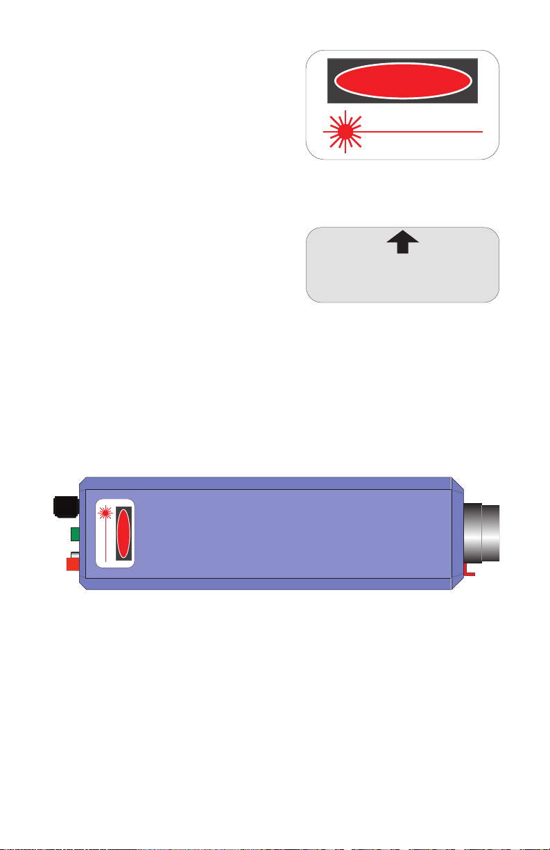
2. Beam Stop
TThe beam stop (also known as a beam attenuator) is required on lasers by federal
regulations. When viewed from the rear of the laser, its handle protrudes from the
right side of the optics mount. Its function is to mechanically block the laser beam
when the handle is pushed downward. When the handle is pushed upward, the beam
stop rotates and allows the laser beam to exit the lasing apparatus.
1193
AVOID EXPOSURE
LASER RADIATION EMITTED
FROM THIS APERTURE
1
2
Figure 2. Front View of Laser with Beam Stop
Blocking the Laser Beam

– 6 –
SPECIFICATIONS
Caution: Use of controls or adjustments or performance of procedures other than those
specified herein may result in hazardous radiation exposure.
Specifications for laser model numbers IF-RL05-6351, IF-RL08-6351, IF-RL30- 6351, and
IF-RL30-6701are shown in Table 3.
Models and Laser Classications
Table 3. Laser Specications
Parameter Value Units
Operating
Input voltage 10 to 15 volts
Input current 60 to 125 milliamperes
Temperature 0 to 40 ° C
Optical
Polarization Linear
Wavelength 630 - 6751nm
Output power See label2mW
Beam diameter 3.2 mm
Beam divergence, max 2 milliradians
Electrical
Analog modulation310 to 500 kHz
Digital modulation30 to 500 kHz
Storage
Dimensions 5.6 x 7.5 x 22 cm
Weight 400 grams
Temperature -20 to 50 ° C
1 The lasing wavelength, in nanometers, is the last three numbers in the part number
located on the underside of the laser chassis.
2 Label is located on the bottom side of the laser.
3 Refer to the section on electrical controls in this manual for more information
Table 4. CDRH Classications for laser models.
Laser Model Classication Typical power levels
IF-RL05-635 CLASS II .4 to .6 mW
IF-RL08-635 CLASS II .75 to .90 mW
IF-RL30-635 CLASS IIIa 2.8 to 3.2 mW
IF-RL30-670 CLASS IIIa 2.8 to 3.2 mW

– 7 –
SAFETY
OPTICAL
All lasers addressed by this manual emit a visible beam of red light. No infrared, ultra-violet,
x-ray or other non-visible radiation is emitted from these products.
This low-power laser cannot be used to burn, cut or drill. Even so, you should use caution,
because the beam is concentrated. It could become focused to a pinpoint within the human
eye. Never look directly into the laser beam or stare at its bright reflections — just
as you should avoid staring at the sun or other very bright light sources.
Review the Rules for Laser Safety on the back cover of this booklet.
ELECTRICAL
Included with this laser is a UL-approved VAC-to-VDC adapter for VAC operation. The
adapter converts common lab/household voltage to low DC voltage suitable for laser use.
Always plug the adapter into a grounded circuit.
This laser is particularly safe because it operates at low wattage and low current levels.
However, as when using any electrical device, you must take certain safety precautions:
• Do not touch (or short-circuit) the connection point at which incoming power from
the adapter enters the laser housing, as this could damage the power supply.
• Do not open the laser housing under any circumstances, as this will expose you
to unshielded electrical connections, violating federal government regulations and
voiding the product warranty.

– 8 –
LASER REGULATIONS
The U.S. Department of Health, Education and Welfare regulates and classifies all laser
products sold in the United States. Industrial Fiber Optics lasers comply fully with laser
performance standards established by Center for Devices and Radiological Health (CDRH)
Regulation 21, parts 1040.10 and 1040.11, Code of Federal Regulations.
Specific labeling is required by Federal Regulations on all laser products. For your safety
and that of others, do not remove any of the labels.
Certication/ Identication
Laser certification and iden-
tification labeling required
by federal regulations have
been combined in a single
label located on the under-
side of the laser. A graphic
representation of that label is
shown in Figure 3. It certifies
that this laser complies with
federal regulations; identifies
the manufacturer; and lists
the model number and date of
manufacture.
Classications
All lasers described by this manual fall within the limitations of Class II and Class IIIa of
CDRH standards. All lasers covered by this manual will exhibit a label located on the top,
rear of the laser chassis as shown in Figure 7.
Class II lasers may not exceed 1 milliwatt
(1 mW) of output power, must contain a pilot
light and a beam attenuator. An example of the
“warning logotype” label used for Class II lasers
is shown in Figure 4.
No User Serviceable Parts Inside
This LASER product complies with
C.D.R.H. Regulation 21 CFR 1040.10 and 10410.11
Model Number:
Output Power:
Manufacturing Date:
Serial Number:
Manufactured by:
INDUSTRIAL FIBER OPTICS, INC.
1725 West 1st Street
Tempe, AZ 85281-7622
1188.eps
Figure 3. Laser certication
and identication label.
CAUTION
LASER RADIATION
DO NOT STARE INTO BEAM
PEAK POWER 1 mW
WAVELENGTH 600 - 700 nm
Class II Laser Product
1189.eps
Figure 4. Warning logotype label
for Class II lasers.
– 9 –
Class IIIa lasers have an output power limitation
between 1 and 5 milliwatts, and require a pilot
light and a beam attenuator. The “warning
logotype” label required for this classification of
laser is shown in Figure 5.
Aperture Labels
Federal regulations also require that the laser
emission aperture/port be labeled. A graphic
representation of that label is shown in Figure
6. Location of this label is shown in Figure 2.
Additional References
For more information about lasers and laser
standards, contact your local U.S. Department
of Health and Human Services, or write to the
agency’s headquarters at 1390 Piccard Dr.,
Rockville, MD 20850.
For U.S. guidelines on laser classifications and health standards, refer to the American
National Standards Institute (ANSI) specifications governing lasers and laser safety. The
guidelines are published by the Laser Institute of America, 12424 Research Parkway,
Suite 130, Orlando, FL 32826.
LASER RADIATION
DO NOT STARE INTO BEAM
PEAK POWER 5 mW
WAVELENGTH 600 - 700 nm
Class IIIa Laser Product
DANGER
1190.eps
AVOID EXPOSURE
LASER RADIATION EMITTED
FROM THIS APERTURE
1191.eps
Figure 5. Warning logotype label
for Class IIIa lasers
Figure 6. Beam aperture label.
1209.eps
LASER RADIATION
DO NOT STARE INTO BEAM
PEAK POWER 5 mW
WAVELENGTH 600 - 700 nm
Class IIIa Laser Product
DANGER
Figure 7. Top view of laser showing the location of the
“warning logotype” label for a Class IIIa laser.

– 10 –
OPERATING PROCEDURES
Non-modulation Or CW Operation
1. Review the laser safety steps on the back cover of this manual.
2. Point the laser toward a wall or other dull non-reflecting surface.
3. Push the beam stop’s handle downward to its closed position.
4. Make sure the laser’s ON/OFF switch (SW) is in its OFF position.
(The push button should be in its extended position.)
5. Plug the 110* VAC-to-DC power adapter (provided with the laser)
into an AC wall outlet.
Important: If you must use a power adapter other than the one supplied with this laser,
check the section entitled Operational Information in this manual to ensure
the power adapter’s voltage and current levels are within recommended
specifications
6. Plug the cord from the power adapter into the power jack (PWR) located
on the rear of the laser.
7. Depress the ON/OFF switch (SW) on the control panel of the laser until
it clicks into the ON position. (The switch should be slightly depressed.)
8. The pilot light (green LED) just to the left and below the ON/OFF switch
should now be lit, showing that the laser is on.
9. Push the beam stop’s handle upward, to its open position.
10. Observe the red beam striking the wall, or other surface, in the direction
which the laser is pointed.
* 220 VAC for most customers outside of North America

– 11 –
Using Laser With Microphone
We will outline the steps for using a microphone with your Industrial Fiber Optics diode
laser. Because we don’t know what receiver you will use to convert the optical signal on
the laser beam to sound, please refer to that receiver’s instruction manual as directed in
the procedure below.
1. Complete Steps 1 through 10 on page 10.
2. Push the beam stop to its closed position, and make sure the laser’s ON/
OFF switch is OFF. (The button should be extended and the pilot light no
longer illuminated.)
3. Plug the 3.5 mm plug on the end of the microphone cord into the
3.5 mm audio jack.
4. Point the laser toward a wall or other non-reflecting dull surface.
5. Set up your laser receiver, referring to its manual for operating proce-
dures.
6. Press the ON/OFF switch (SW) on the control panel of the laser. The
laser now should be on, as indicated by the pilot light.
7. Rotate the beam stop’s handle upward, to its open position.
8. Target the laser beam on the light detector found on the laser receiver.
9. Position the receiver or laser as needed, so the laser light beam strikes the
center of the receiver detector.
10. If a high-pitched squeal is produced by the laser receiver and speaker,
reduce the volume at the receiver.
11. Speak into the microphone. If you cannot hear yourself, bring the
microphone closer to your mouth and/or increase laser receiver volume.
Your laser and receiver should now be functioning as a free-space optical voice link.
You should be hearing your voice or music from the audio receiver.
Figure 8. Class IIIa laser and laser beam aligned with an Industrial Fiber Optics’
audio laser receiver for demodulation of the laser beam’s modulated signal and
producing sound waves.

– 12 –
TROUBLESHOOTING
No Pilot Light
• Is the laser’s ON/OFF switch in the ON position?
• Is the 110 (220) VAC-to-VDC power adapter plugged into the laser and an
appropriate wall outlet or extension cord?
• Is there power to the wall outlet?
No Laser Light Output
• Is the ON/OFF switch in the ON position?
• Is the 110 (220) VAC-to-VDC power adapter plugged into the laser and an
appropriate wall outlet or extension cord?
• Is there power to the wall outlet?
• Is the pilot light on?
• Is the mechanical beam stop in its open position?
No Modulation from Receiver
• Is the laser beam positioned properly so its beam hits the receiver detector?
• If you are using an analog or digital input banana jack, is it properly connected,
including a “ground” connection?
• Are input signals to the laser of sucient amplitude? (See microphone, analog
and digital portions in the Electrical section of this manual.)
• Slowly move the receiver detector out of the path of the laser beam while
continuously monitoring receiver operation. (This would desensitize the
receiver in case the receiver is too sensitive for this laser [saturating].)
• Check the troubleshooting section in your laser receiver manual.
Do not attempt to troubleshoot the laser beyond the steps listed above. If all your
connections are correct, and you are confident that power is being supplied to the laser and
any input devices, please return the laser for appropriate inspection/servicing to Industrial
Fiber Optics, as described in the section entitled SERVICE AND MAINTENANCE.

– 13 –
SERVICE AND MAINTENANCE
Periodic operation, maintenance and service of this laser are not required. The warranty
will be voided if entry has been made to the laser housing and/or any screws have
been removed.
In the unlikely event this laser malfunctions and you wish to have it repaired, please do
the following:
• Contact us to request an RMA number.
• Carefully pack the laser, power adapter, manual, and written description in a
stout box with sucient packing material to prevent damage in shipment.
• Ship the package with assigned RMA number to:
IndustrIal FIber OptIcs
W S
T, AZ -
USA

– 14 –
WARRANTY
Industrial Fiber Optics diode lasers are warranted against defects in materials and
workmanship for 4 years. The warranty will be voided if the laser components have been
damaged or mishandled by the buyer, including entry to the laser housing and/or removal
of screws.
Industrial Fiber Optics’ warranty liability is limited to repair or replacement of any defective
unit at the company’s facilities, and does not include attendant or consequential damages.
Repair or replacement may be made only after failure analysis at the factory. Authorized
warranty repairs are made at no charge, and are guaranteed for the balance of the
original warranty.
Industrial Fiber Optics oers to pay the return freight for warranty repair within the
continental United States by United Parcel Service. Any other delivery means must be paid
for by the customer.
The costs of return shipments for lasers no longer under warranty must be paid by the
customer. If an item is not under warranty, repairs will not be undertaken until the cost
of such repairs has been approved, in writing, by the customer. Typical repair costs start at
$65, and repairs usually take one to two weeks to complete.
When returning items for analysis and possible repair, please do the following:
In a letter, describe the problem, person to contact, phone number and return
address. Contact us to request an RMA number.
• Pack the laser, power adapter, manual and letter carefully in a strong box
with adequate packing material to prevent damage in shipment.
• Ship the package with provided RMA number to:
IndustrIal FIber OptIcs
W S
T, AZ -
This manual suits for next models
2
Table of contents
Other Industrial Fiber Optics Measuring Instrument manuals

Industrial Fiber Optics
Industrial Fiber Optics ML 800 Series User manual

Industrial Fiber Optics
Industrial Fiber Optics ML 801 User manual

Industrial Fiber Optics
Industrial Fiber Optics IF 535 Manual

Industrial Fiber Optics
Industrial Fiber Optics 45-545A User manual

Industrial Fiber Optics
Industrial Fiber Optics IF User manual


