Industrial Separation Systems VGS User manual

VGS
VGSVGS
VGS
Oily Water Separator
T
Te
ec
ch
hn
ni
ic
ca
al
l
M
Ma
an
nu
ua
al
l
Version: OWS-JUL.08

VGS Oily Water Separator Technical Manual
Version: OWS-July 2008 30 July 2008 Page 2
Vertical Gravity Separators
are proudly manufactured in Australia by:
Industrial Separation Systems
ACN: 105 667 374
Unit 10-141 Taren Point Road,
TAREN POINT, NSW 2229 Australia.
Phone: +61 2 9524 6654
Facsimile: +61 2 9524 6685
Email: sales@issproject.com.au
Web Site: www.issproject.com.au

VGS Oily Water Separator Technical Manual
Version: OWS-July 2008 30 July 2008 Page 3
This Technical Manual has been produced to aid designers, engineers, plumbers and
regulatory authorities in the identification, selection, installation & maintenance of the Vertical
Gravity Separator (VGS)
Contents
Introduction
Product overview ............................................................................ 4
Features & Benefits ........................................................................ 4
Approvals........................................................................................ 5
The Technology
Principle of Operation ..................................................................... 6
VGS Options
Flow Rates...................................................................................... 7
Material ........................................................................................... 7
Mounting ......................................................................................... 7
Oil Level Control ............................................................................. 7
Pumps............................................................................................. 7
Electric Motor.................................................................................. 7
Control Panels ................................................................................ 7
Pump Types for VGS Systems....................................................... 8
VSG Specifications......................................................................... 9
VGS Coding.................................................................................... 10
Compliance Plate Details ............................................................... 11
Dimensions - Free Standing, Polyethylene .................................... 12
- Stand Mounted, Polyethylene ................................... 13
- Free Standing, 304 Stainless Steel........................... 14
Installation
Location .......................................................................................... 15
Assembly ........................................................................................ 15
Pipe Connections ........................................................................... 16
Sewer Connections ........................................................................ 17
Electrical Connections .................................................................... 17
Typical Installation Schematic ........................................................ 18
Commissioning
Pre-Set Oil Level Models................................................................ 19
Adjustable Oil Level Models ........................................................... 19
Maintenance ............................................................................... 20
Maintenance Schedule ................................................................... 21
Trouble Shooting ..................................................................... 22
Warranty .........................................................................23
Apendix A.......................................................................24
Apendix .......................................................................25
VGS Oily Water Separator Technical Manual
Version: OWS-July 2008 30 July 2008 Page 4
Introduction
Product Overview
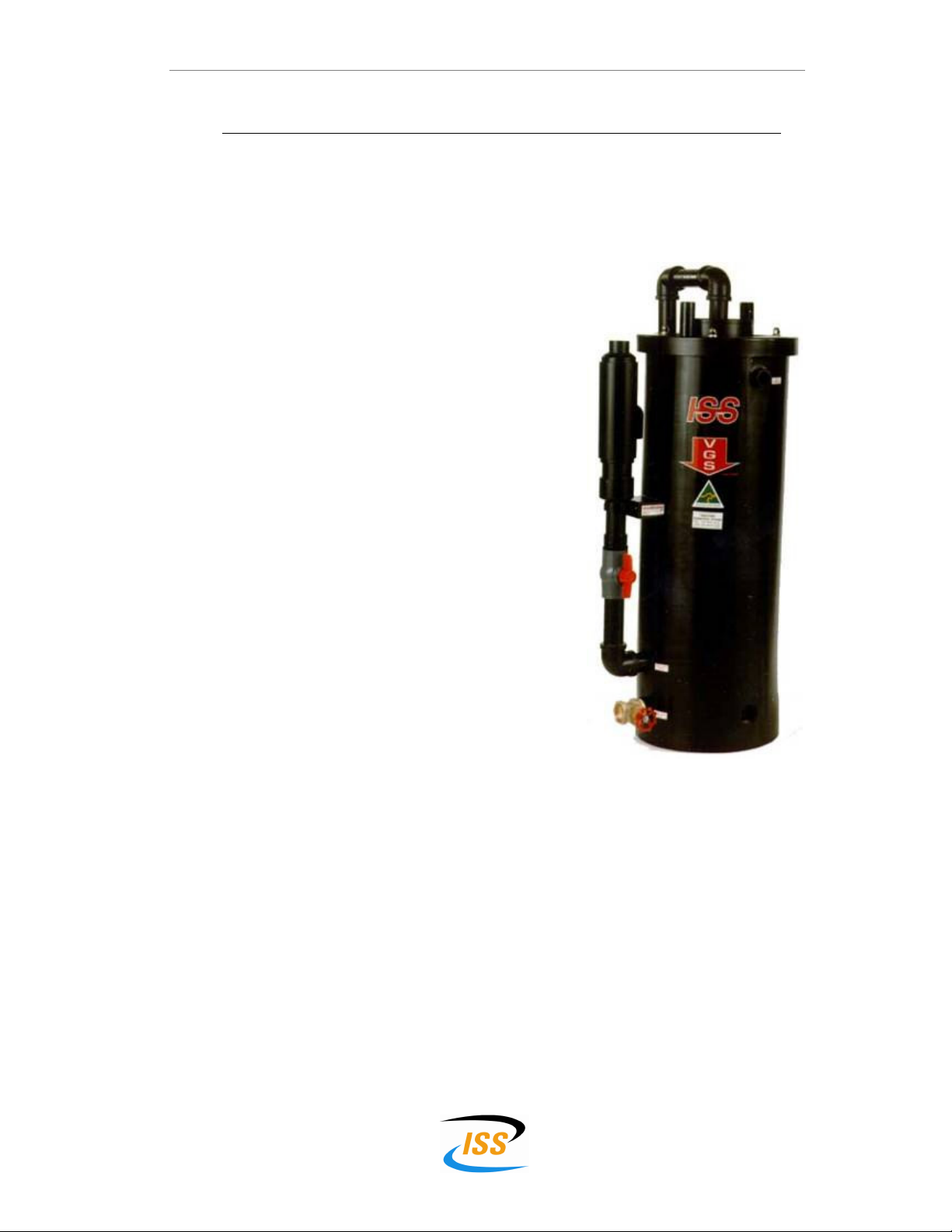
The Vertical Gravity Separator (VGS)is an oil/water separator developed to
effectively remove free oil, grease and low density suspended solids from
wastewater.
The VGS operates by ingenious control of both fluid
velocity and pressure. These forces gently coax non-
emulsified impurities from water by allowing high density
contaminants to fall into a sludge retaining area at the
bottom of the vessel, and oil droplets and low density
suspended solids to rise to the top of the vessel. The oil
and suspended solids then drain off into a waste tank for
disposal.
Acclaimed by major water authorities around the world
as "the best technology of its kind", the VGS can be
used as a stand-alone separator or to supplement the
performance of existing systems.
Because it stays clean it maintains its performance!
Features & Benefits
Performance
Due to its ingenious design the VGS is capable of
continually meeting the performance standards set by
the Sydney Water Corporation, and other regulatory
authorities, in respect to Petroleum Hydrocarbons, Total
Oil & Grease, Suspended Solids and Flammability.
Suspended Solids
Low density suspended solids are encapsulated by the oil and progress to the top of
the VGS for discharge to the waste tank. Heavy solids settle to the base of the unit
and are removed from the system by the way of a control valve.
Flammability
The turbulent flow principle of the VGS ensures the vapour content of the wastewater
being treated is reduced to safe levels.
Construction
By utilizing a vertical cylinder design the VGS requires far less floor space compared
to a coalescing plate separator.
Maintenance
Unique design features enable quick, on-line cleaning of the unit; a feature only
found on the VGS. There is no need to remove the oleophilic cones and use high
pressure jets or chemicals to clean the VGS, as is the case with conventional
separators.
VGS Oily Water Separator Technical Manual
Version: OWS-July 2008 30 July 2008 Page 5
Approvals
Since its invention in 1992 the VGS has progressively gained approval from water
treatment authorities, local councils & other government bodies throughout Australia.
Approvals include:
Authority State
Sydney Water Corporation NSW
Dept. Land & Water Conservation NSW
Hunter Water Corporation Limited NSW
A.C.T.E.W. Australian Capital Territory ACT
South Australian Water Corporation SA
Western Australian Water P.T.L WA
Brisbane City Council QLD
Townsville City Council QLD
Ipswich City Council QLD
Power & Water Authority NT

VGS Oily Water Separator Technical Manual
Version: OWS-July 2008 30 July 2008 Page 6
The Technology
Principle of Operation
The Vertical Gravity Separator (VGS) is a flooded system in which the inlet and outlet
columns form a U - tube configuration. The free oil and low density suspended solids
are trapped on one side of the main body and the treated water flows out the other
side.
The main body of the unit contains
a continuous truncated conical
spiral pack (SPAK) which is
manufactured from an oleophilic
material. Oily water is delivered into
the bottom of the main body where
it then flows upwards through the
centre of the SPAK assembly.
At the top of the main body free oil
and low density suspended solids
are held and eventually they flow
out of the system into a waste tank.
The partially cleaned water is
directed to the outside perimeter of
the conical SPAK. It then follows a
tortuous path cascading down and
around the SPAK.
Here the lower density fluid (oil) is
drawn up the incline of the
oleophilic surface of the SPAK and
back into the low pressure centre of
the VGS, where it co-mingles with
the incoming fluid and is redirected
to the top of the main body.
A convection current is thus
created within the SPAK by the
density variation down the fluid
column and the upward flow of the
incoming oily water.
The ‘treated’ water will enter the
output leg, at a point when the fluid
is most free of contaminants, and
flow up and out of the system.
Heavy solids and sludge are removed from the system via a sludge valve at the base
of the main body.
Fig. 1 - VGS Schematic Diagram

VGS Oily Water Separator Technical Manual
Version: OWS-July 2008 30 July 2008 Page 7
VGS Options
The modular design of the VGS allows for a variety of different options to be ordered
depending on the specific site requirements.
Flow Rates
The range of VGS’s covers flow rates from 1000 L/h up to 3000 L/h. Flow rates
above this can be achieved by installing multiple units.
Please contact ISS or your local distributor for further assistance.
Material
The main body and the rotating lid of the VGS is manufactured from either:
•6 mm High Density Polyethylene which has been roto-moulded using the
latest production techniques.
•1.6 mm 304 grade Stainless Steel, which is designed for installation in the
most harsh environments.
Mounting
Where the amount of sludge within the waste water being treated is minimal, a flat
bottom/free standing VGS is available. (1000 and 1500 L/h models only)
Standard VGS units have an extended cone shape bottom for sludge retention. A
three post stand is supplied with the VGS
Oil Level Control
Two types of oil level control are available:
•Pre-Set Level of oil held within the VGS is pre-set in the factory.
•Adjustable Level of oil held within the VGS is adjustable on site.
Pumps
The “Pump Types for VGS Systems” table on page 8 lists the different types of
pumps that can be utilised within a VGS system.
Electric Motor
Either single phase 240 V or three phase 415 V, standard or flameproof, motors are
available depending on the application.
Control Panels
Built to specification, depending on the application.

VGS Oily Water Separator Technical Manual
Version: OWS-July 2008 30 July 2008 Page 8
Pump Types for VGS Systems
VGS Details Pump Details
Model Flow
Rate Type Brand Model Speed kW
V10P0FP 700 L/h Positive Displacement Mono CP11RJ 1450 rpm 0.18
V10P0FD 1000 L/h Diaphragm ASM DS25 30 spm 0.25
V15P3FP 1600 L/h Positive Displacement Mono CP25RJ 1450 rpm 0.37
V15P0FD
V15P3FD
V15P3AD
1500 L/h Diaphragm ASM DS25 42 spm 0.37
V20P3AD 2000 L/h Diaphragm ASM DS32 48 spm 0.37
V30P3AP 2700 L/h Positive Displacement Mono CP800RJ 960 rpm 0.55
V30P3AD
V30S0FD
3000 L/h Diaphragm ASM DS38 36 spm 0.55
•Minimum size pump well before VGS
Sydney Water require that the pump well is to have a working volume of at least 500
litres, ie the volume held by the well between the high level (ON) switch and the low
level (OFF) switch level.
•Specifications for progressive cavity Mono CP range pumps
Rotor: 316 Stainless steel, Hard Chrome Plated (HCP)
Stator: NB70HND Accelerated nitrile (RJ)

VGS Oily Water Separator Technical Manual
Version: OWS-July 2008 30 July 2008 Page 9
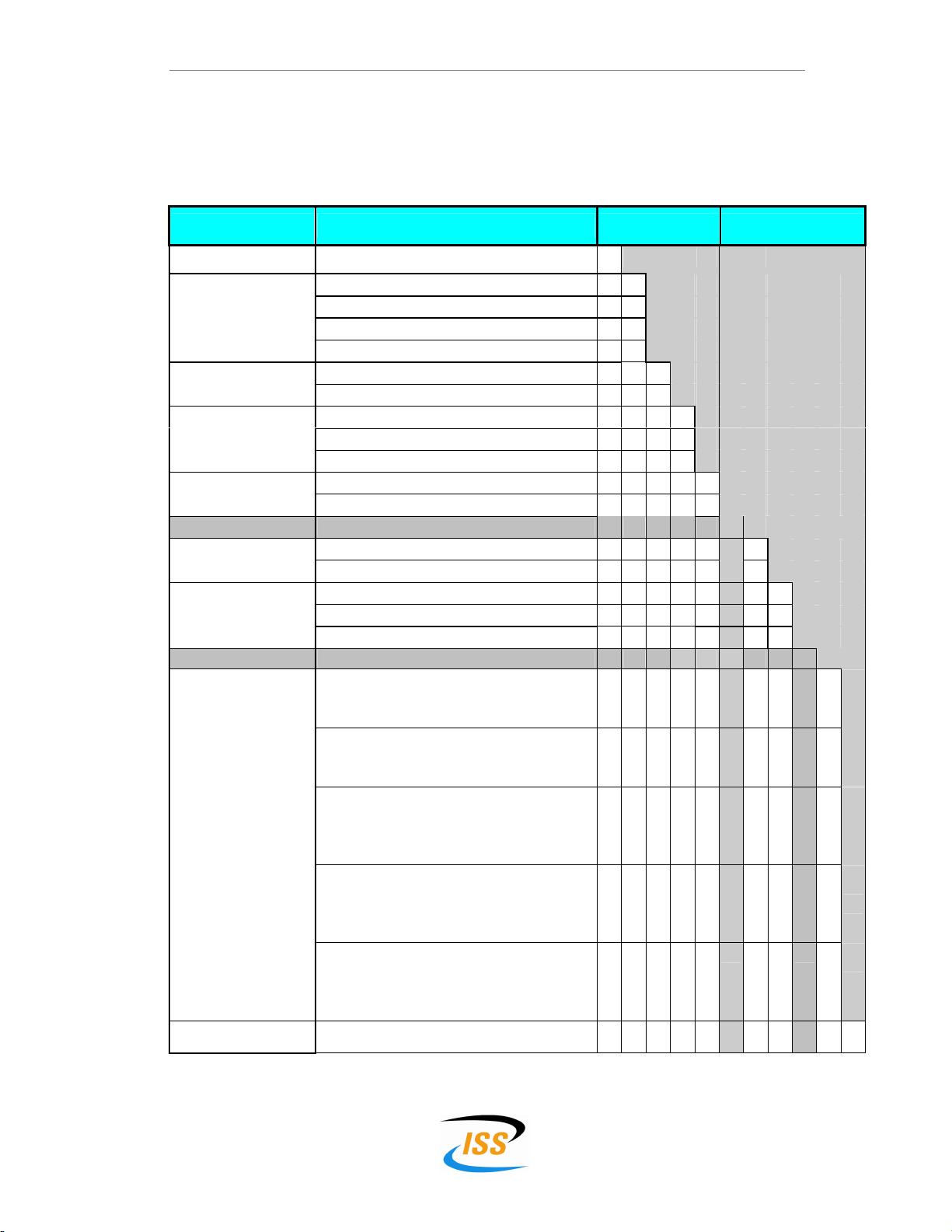
VGS Specifications
Model Details
V – VGS
10 – 1000 L/h
15 – 1500 L/h
20 – 2000 L/h
30 – 3000 L/h
P – H.D Polyethylene
S - Stainless steel
F - Fixed Adjuster
A – Adjuster
P- Positive
displacement
D- Diaphragm
Weight
in
kg
25
25
35
35
35
38
43
External Pipe
& Fittings
Polypropylene &
UPV lass 12
Polypropylene &
UPV lass 12
Polypropylene &
UPV lass 12
Polypropylene &
UPV lass 12
Polypropylene &
UPV lass 12
Polypropylene &
UPV lass 12
Polypropylene &
UPV lass 12
Valves
Backwash - 50mm Poly.
Sludge - 25mm Brass
Backwash - 50mm Poly.
Sludge - 25mm Brass
Backwash - 50mm Poly.
Sludge - 50mm Brass
Backwash - 50mm Poly.
Sludge - 50mm Brass
Backwash - 50mm Poly.
Sludge - 50mm Brass
Backwash - 50mm Poly.
Sludge - 50mm Brass
Backwash - 50mm Poly.
Sludge - 50mm Brass
Base
(Free
Standing)
(Free
Standing)
Galvanised
Stand
Galvanised
Stand
Galvanised
Stand
Galvanised
Stand
(Free
Standing)
SPAK
HD
Polyethylene
HD
Polyethylene
HD
Polyethylene
HD
Polyethylene
HD
Polyethylene
HD
Polyethylene
HD
Polyethylene
Lid
(Thickness/Type)
Polyethylene
(6mm/H.D.)
Polyethylene
(6mm/H.D.)
Polyethylene
(6mm/H.D.)
Polyethylene
(6mm/H.D.)
Polyethylene
(6mm/H.D.)
Polyethylene
(6mm/H.D.)
Polyethylene
(6mm/H.D.)
Material
Tank
(Thickness/Type)
Polyethylene
(6mm/H.D.)
Polyethylene
(6mm/H.D.)
Polyethylene
(6mm/H.D.)
Polyethylene
(6mm/H.D.)
Polyethylene
(6mm/H.D.)
Polyethylene
(6mm/H.D.)
Stainless Steel
(1.6mm/304)
Flow
Rate
in
L/h
1000
1500
1500
1500
2000
3000
3000
Model
V10P0F
V15P0F
V15P3F
V15P3A
V20P3A
V30P3A
V30S0F
VGS Oily Water Separator Technical Manual
Version: OWS-July 2008 30 July 2008 Page 10
VGS Coding
Features Details Basic Coding Optional Extras
Separator Vertical Gravity Separator V
1000 L/h 10
1500 L/h 15
2000 L/h 20
Nominal flow rate
3000 L/h 30
Polyethylene - High Density P
Material 304 Stainless Steel S
Free Standing (1000 & 1500 L/h flow only) 0
3 Post Galvanised Stand 3
Mounting
Adjustable A
Oil level control Fixed Pre-Set F
/
Progressive Cavity P
Pump Diaphragm Pump D
Standard 240 volt 1
Standard 415 volt 3
Electric Motor
Flameproof 415 volt - AS2380-1 & AS2380-2 4
/
Polyethylene 240/24 VAC Starter w/-
- Manual/Off/Auto
- Pump & float terminals.
A
Polyethylene 415/24 VAC Starter w/-
- Manual/Off/Auto
- Pump & float terminals.
B
Metal 240/24 VAC Starter w/-
- Manual/Off/Auto
- Pump running light
- Pump & float terminals
C
Metal 415/24 VAC Starter w/-
- Manual/Off/Auto
- Pump running light
- Pump & float terminals
D
Control Panel
Metal 415/24 VAC INTRINSICALLY SAFE Starter
- Manual/Off/Auto
- Pump running light
- Pump & float terminals
F
Control panel option High level visual/audible alarm & mute button 1

VGS Oily Water Separator Technical Manual
Version: OWS-July 2008 30 July 2008 Page 11
Compliance Plate Details
All VGS units have a “Compliance Plate” permanently attached to the tank.
The details are as follows:
Material: 1.0 mm thick aluminium
Size: 80mm x 40mm
VGS Flow rate – L/h
VGS Serial Number
Pump Serial No.
Pump Flow rate – L/h
Sydney Water
Authorisation Number
MODEL
ISS Ph (02) 9524 6654
S/No.
PUMP
MODEL
AUTHORISATION NUMBER 2003-XX
L/hr
PUMP
RATE L/h
PUMP
SERIAL NO.
VGS Model Number
Pump Model
VGS Oily Water Separator Technical Manual
Version: OWS-July 2008 30 July 2008 Page 12
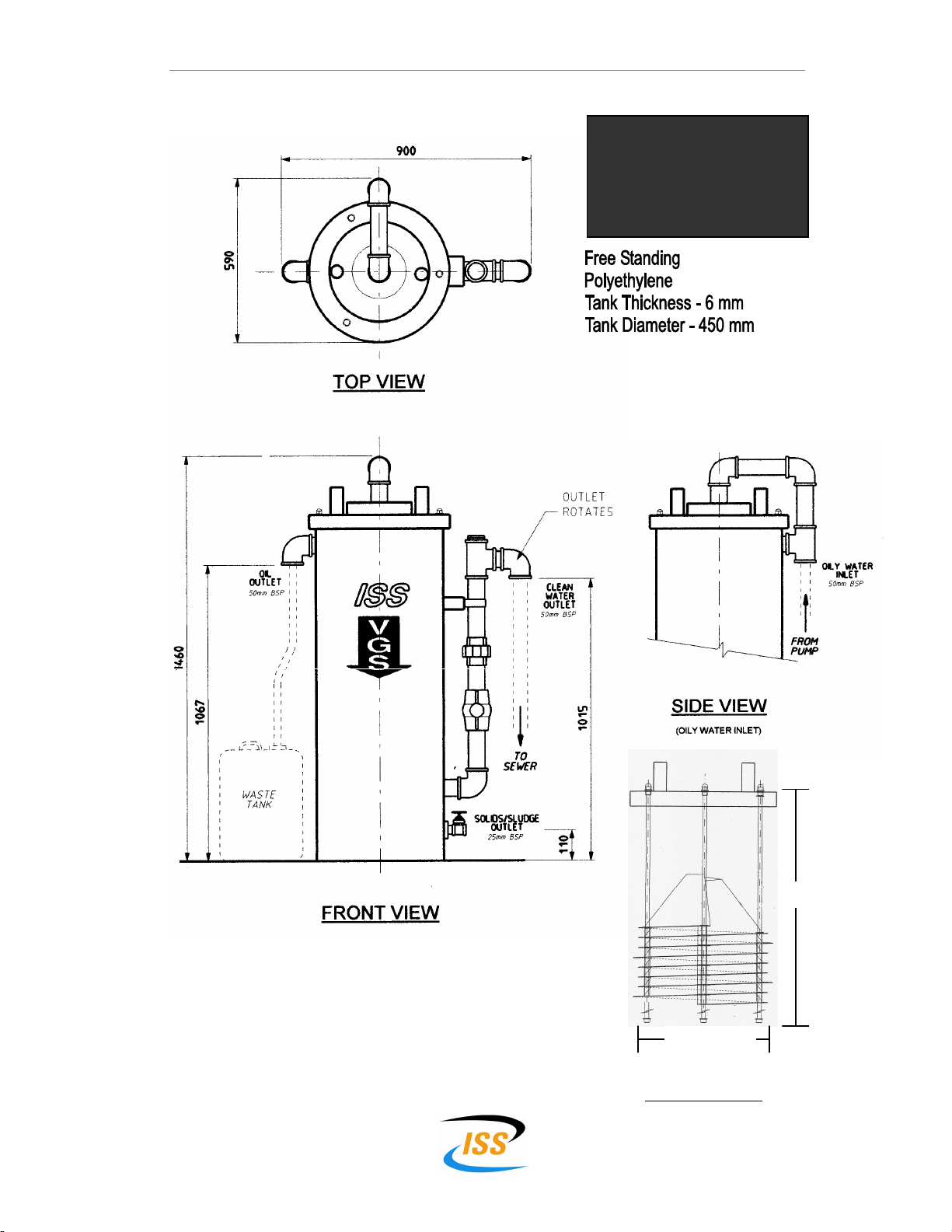
Dimensions
VGS Models:
V10P0FD
V10POFP
V15P0FD
SPAK Assembly
435 mm
950 mm

VGS Oily Water Separator Technical Manual
Version: OWS-July 2008 30 July 2008 Page 13
Dimensions
SIDE VIEW
(OILY WATER INLET)
TOP VIEW
FRONT VIEW
VGS Models:
V15P3FD
V15P3FP
V15P3AD
V20P3AD
V30P3AD
V30P3AP

VGS Oily Water Separator Technical Manual
Version: OWS-July 2008 30 July 2008 Page 14
Dimensions
SIDE VIEW
(OILY WATER INLET)
TOP VIEW
REAR VIEW
VGS Models:
V30SOFD
No Back flush
valve shown
VGS Oily Water Separator Technical Manual
Version: OWS-July 2008 30 July 2008 Page 15
Installation
Location
The VGS should be placed on a level concrete base to Australian Standard to
support a minimum 250 kg.
Note: The VGS must be installed LEVEL
Position the VGS in a location that has no less than 1100 mm of clear space above
the unit to allow for future removal of the SPAK.
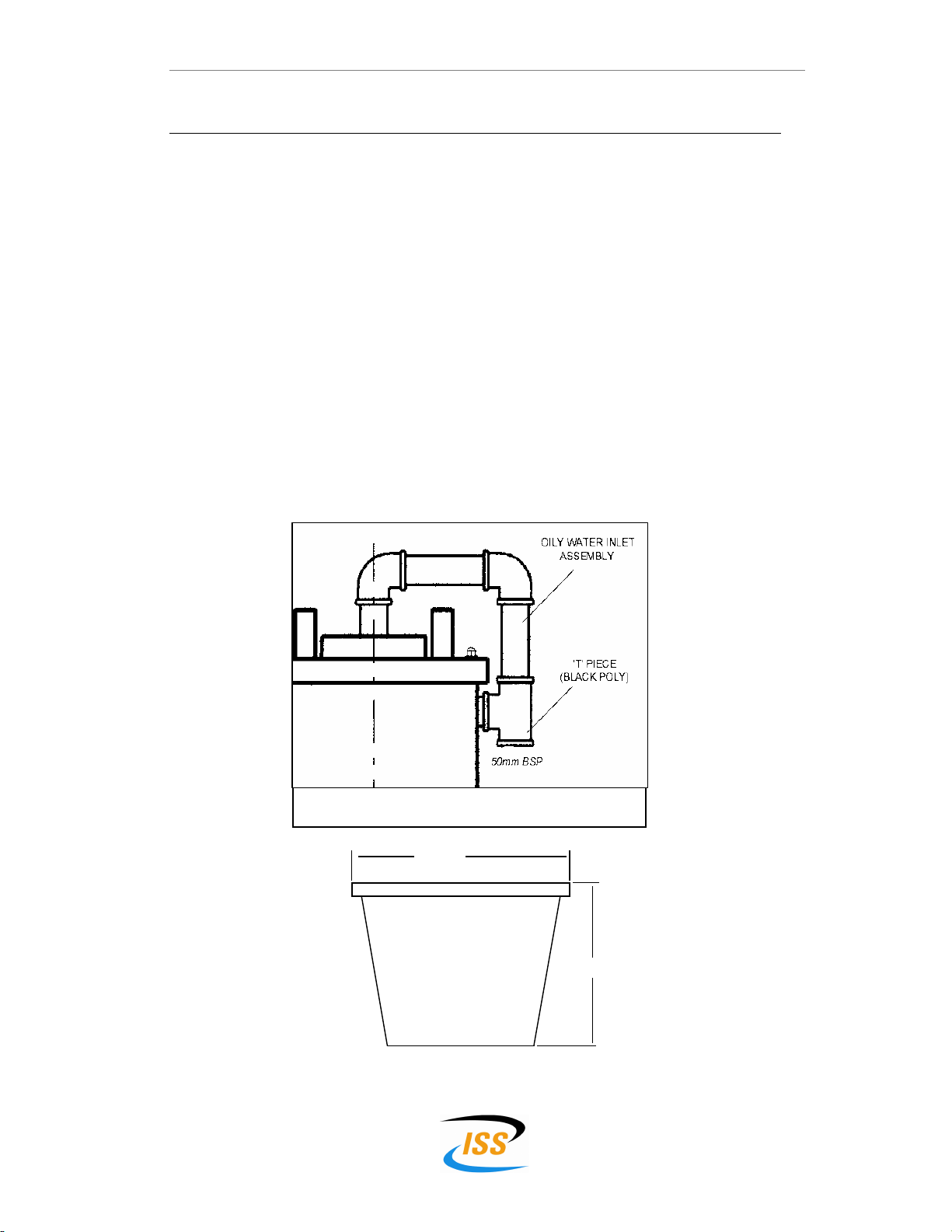
Assembly
The Oily Water Inlet 1
11
1must be assembled by:
1. Screwing the ‘T’ piece to the blanked off 50 mm male thread at the top of
the main body labelled OIL WATER INLET.
2. Fixing the Oily Water Inlet assembly to the ‘T’ piece.
Fig 2 - Oily Water Inlet
190 mm
125 mm
STRAINER BASKET FITTED IN THE TOP OF
THE VGS UNIT
VGS Oily Water Separator Technical Manual
Version: OWS-July 2008 30 July 2008 Page 16
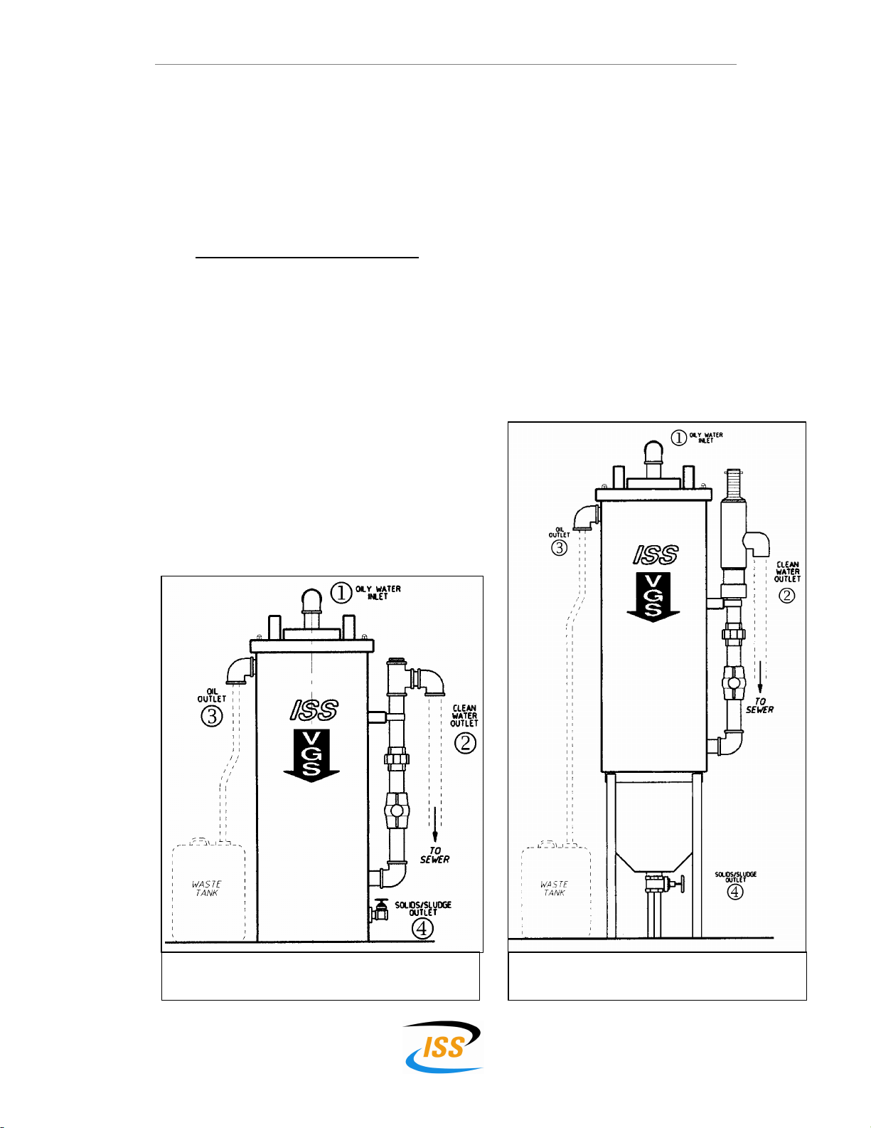
Pipe Connections
1. Connect the discharge pipe from the pump to the Oily Water Inlet 1
11
1(Fig 3 &
4) using class 6 PVC pressure pipe. Refer to ASM appendix A and Mono
appendix B, pages 24 & 25 respectively.
2. Install a 50 mm DWV PVC discharge pipe between a sewer tundish (see Sewer
Connection on page 17) and the Clean Water Outlet 2
22
2.
A minimum vertical fall of 600 mm from the Clean Water Outlet must be
maintained to ensure correct operation of the VGS.
3. Install a suitable oil resistant discharge pipe from the Oil Outlet 3
33
3to a waste
tank. (Not supplied), same size as the pump discharge line. Polyethylene is a
suitable material.
4. Fit the gate valve supplied with the VGS to the Sludge/Solids Outlet 4
44
4at the
base of the tank.
Fig 3 - Installation details
“Free Standing” type VGS units.
Fig 4 - Installation details
“Stand Mounted” type VGS units.

VGS Oily Water Separator Technical Manual
Version: OWS-July 2008 30 July 2008 Page 17
Sewer Connections
The treated water from the VGS should be discharged to sewer via an inlet riser to a
gully as detailed in Fig 5 below. This point can be used for sampling the quality of
the effluent being discharged.
Electrical Connections
A licensed Electrical Contractor must connect the pump supplied with the VGS, to the
electrical supply.
If the wastewater being treated has flammable Class 3 liquids present, such as
petrol, kerosene or other solvents, all electrical equipment within a defined area must
be suitably rated.
Extract from
Sydney Water
documentation
Fig 5 - VGS Sewer Connection Detail

VGS Oily Water Separator Technical Manual
Version: OWS-July 2008 30 July 2008 Page 18
Typical Installation Schematic
BUNDED AREA
VGS Oily Water Separator Technical Manual
Version: OWS-July 2008 30 July 2008 Page 19
Commissioning
Pre-Set Oil Level Models
The following procedure should be carried out when commissioning a VGS that has a
pre-set oil level.
Step 1 Place waste tank under the oil outlet.
Step 2 Charge the VGS by filling the main body, via the opening in the lid,
with clean tap water (using a hose). The VGS is full when water
starts to flow out of the clean water outlet.
Step 3 Prime the pump by filling both the suction and discharge lines with
water then start the pump.
The VGS is now set correctly and will perform without further adjustment.
Note: Oil will not be seen to discharge from the oil outlet untill sufficient oil has built
up in the top of the unit. This may take some time depending on the quality of the
wastewater being treated.
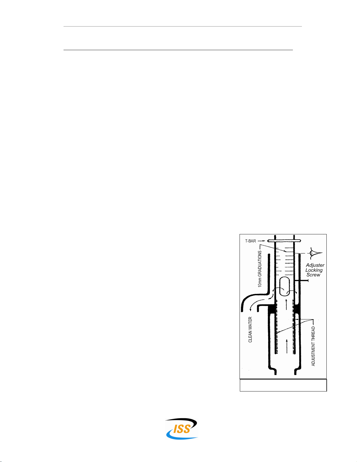
Adjustable Oil Level Models
The following procedure should be carried out when commissioning a VGS fitted with
an adjustable oil level controller.
Step 1 Place waste tank under the oil outlet.
Step 2 Charge the VGS by filling the main body, via
the opening in the lid, with clean tap water
(using a hose).
Step 3 Prime the pump by filling both the suction and
discharge lines with water then start the pump.
Step 4 Loosen the adjuster locking screw.
Step 5 Rotate the ‘T-Bar’ in an ANTICLOCKWISE
direction, thus raising the ‘T-Bar’, until water
flows out of the oil outlet.
Step 6 Rotate the ’T-Bar’ in a CLOCKWISE direction,
thus lowering the ‘T-Bar’, untill the flow from the
oil outlet is reduced to a ‘drip’.
Step 7 Using the 10 mm graduations as a guide
continue to rotate the ‘T-Bar’ clockwise a further
10 mm lower.
Step 8 Tighten the adjuster locking screw onto the ‘T-
Bar’.
The VGS is now set correctly and will perform without further
adjustment.
Note: Oil will not be seen to discharge from the oil outlet untill sufficient oil has built
up in the top of the unit. This may take some time depending on the quality of the
wastewater being treated.
Fig 6 - Oil Level Adjuster

VGS Oily Water Separator Technical Manual
Version: OWS-July 2008 30 July 2008 Page 20
Maintenance
The objective of regular maintenance/cleaning of the VGS is to:
•Fluidise (break-up) any encrustation of surface sludge in the top of the unit.
•Remove any sludge that has become attached to the Continuous Spiral Pack (SPAK).
•Remove settled sludge from the bottom of the unit.
Daily
1) Check the level of the oily waste in the waste tank.
2) Check the operation of the VGS to ensure that there is no oil in the water
flowing out of the CLEAN WATER OUTLET.
Monthly refer to Fig 7 for component recognition
1) Carry out a routine Maintenance Procedure as detailed below:
Step 1 Ensure the waste tank is empty and situated under the oil outlet.
Step 2 Start the pumping cycle by filling the collection pit or switch the Manual/Off/Auto
switch to Manual, if fitted.
Step 3 Crack open the SLUDGE/SOLIDS OUTLET
4
44
4valve at the base of the unit and drain
until the sludge is removed. DO NOT
EMPTY THE VGS.
Step 4 Close the BACK FLUSH VALVE 5
55
5
Step 5 Grip the STIRRING HANDLES 6
66
6on the lid
of the unit & rotate the SPAK in an anti-
clockwise direction for approximately 15
seconds. This will break up any encrusted
surface sludge.
Step 6 Any waste oil will flow into the waste tank.
Allow this to continue until only water flows
into the waste tank. This indicates that the
unit is fully backwashed.
Step 7 Open the BACK FLUSH VALVE 5
55
5
Step 8 Either allow the pit to empty or switch the
Manual/Off/Auto switch back to the Auto
position, if fitted.
2) Ensure that oil, sludge and water outlets are free of blockages at all times.
Fig 7 - Maintenance Diagram
Table of contents
Popular Water Filtration System manuals by other brands

Oase
Oase Bitron 550 LM operating instructions

Xtralis
Xtralis VESDA VSP-005 Cartridge Replacement Instructions

SpectraPure
SpectraPure MarinePRO DI System Installation and operating manual

GRUNDFOS ALLDOS
GRUNDFOS ALLDOS Oxiperm Pro OCD-162 Installation and operating instructions

HYDAC International
HYDAC International OFT20 Operating and maintenance instructions

MTT
MTT MS3719 user manual


