Inel GM35LER-10/09 User manual
DC drive GM35LER-10/09 (N-10LER) with overload detection,
integrated radio and battery charged by solar panel.
Drive with integrated battery, recharged by energy from a solar
panel. The drive is designed for wireless control of guards. In order
for the motor to work correctly with the roller shutter, it is necessary
to use hanger-locks on the winding tube and stoppers in the bottom
bar. The stoppers should be placed as close to the guides as possible
to improve comfort. A sill mustbe fitted to the window and the length
of the guard must match the length of the guides.
Before installing the drive, connect it to the charger and
charge the battery for 6 hours.
Locking hanger –assembly guidelines
The shutter height should be selected to make sure that with the shutter
closed the uppermost slat of the curtain protrudes from the guide up to
half of its height at maximum.
Excessive shutter height may cause faulty operation or even damage. The
hanger length and shutter height must be selected so that the hanger
presses on the first slat of the curtain downwards the guide.
1Safety instructions
1.1 Basic guidelines
The drive is handed over in a condition for safe installation and use,
provided that all instructions in the operating manual are complied with.
Conversion or changes to the drive are not permitted. Warranty repairs
may only be carried out by the manufacturer. Only original spare parts
and accessories should be used for post-warranty repairs. Safe operation
of the supplied drive is only guaranteed when used in accordance with the
manufacturer's specifications. The limits given in the technical data must
not be exceeded under any circumstances.
1.2 Supplementary safety provisions
Important safety and accident prevention regulations must be observed
when installing, commissioning and maintaining the drive. The following
provisions require special attention:
1. Fire regulations.
2. Accident prevention regulations.
1.3 General comments on hazards and safety measures
The comments listed are general guidelines when using INEL equipment
in combination with other equipment. These indications must be strictly
adhered to when installing and operating the equipment.
• Before installing the drive and setting the end positions, check the
tightening of all screw connections.
• The applicable safety and accident prevention regulations must be
observed.
• Wires and cables should be checked regularly for insulation damage
and conductor continuity.
• If the cables are found to be damaged, the damaged cables must be
replaced after the power supply has been switched off immediately.
1.4 Warning
•Do not let children play with the control devices.
•Keep remote control devices out of the reach of children.
•Watch the roller shutter moving and keep bystanders clear until it is
fully open or closed.
•Users of the roller shutter must be trained and instructed on how to
operate the roller shutter and on the dangers involved in its use. People
can be considered trained if the employer, administrator or owner has
allowed them to operate the roller shutter and instructed them on how
to use it.
2Assembly instructions
2.1 Safety rules
▪Inst Installation of the drive must only be carried out by suitably
qualified persons.
▪The weight of the roller shutter must not exceed the load capacity of
the drive as indicated in the selection table (table available at
www.inel.gda.pl).
▪The proper way of laying the cable (loop facing downwards) further
protects the drive from possible water damage.
▪Do not drill holes in the motor housing.
▪Protect the motor from contact with any fluid.
▪Avoid crushing, impact to the motor and protect the motor from falling.
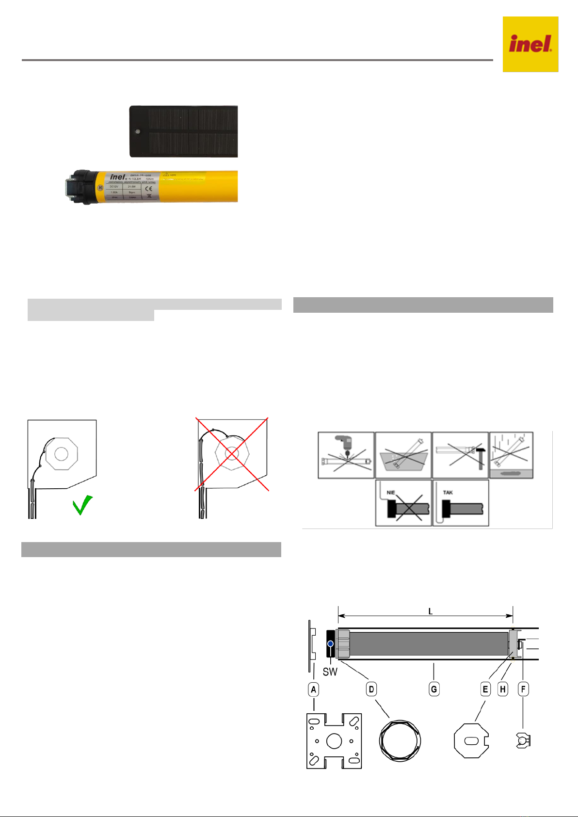
Figure 1
2.2 Assembly of the drive
•Attach the mounting bracket (A) to the side of the roller shutter box,
connect the adapter (D) to the motor drive ring.
•Place the dog (E)supplied with the motor on the motor shaft and secure
it with the pin (F), then slide the entire drive into the winding tube (G).
•Connect the winding tube and the drive dog with screws or rivets (H).
Figure 2
Original instructions PL
Drive installation and operation manual, type: GM
Model: GM35LER-10/09 (N-10LER)
2.3 Electrical connections
After starting, the motor increases its speed until it reaches the optimum
speed.
Check the condition of the guard, guides and roller shutter box
before starting / programming the drive.
The roller shutter box and the guides should be free of dirt and ensure
free movement of the roller shutter guide along its entire length. Guides
that are contaminated with construction material or too tight may cause
damage to the drive and the roller shutter, which is not covered by
warranty.
3Registering the remote control
The drive is compatible with the next remote controls: PIL-01/04NS,
PIL 01/05/09/19PM, PIL-19/99PMT, PIL-01/05/09/19DL,
PIL-19/99DLT, PIL-19/99MMT, PIL-01PT.
Use remote controls from Inel's extensive range (except key fobs) to
control the drive. The remote control must be registered. Registering the
remote control involves memorizing the remote control channel in the
drive's memory.
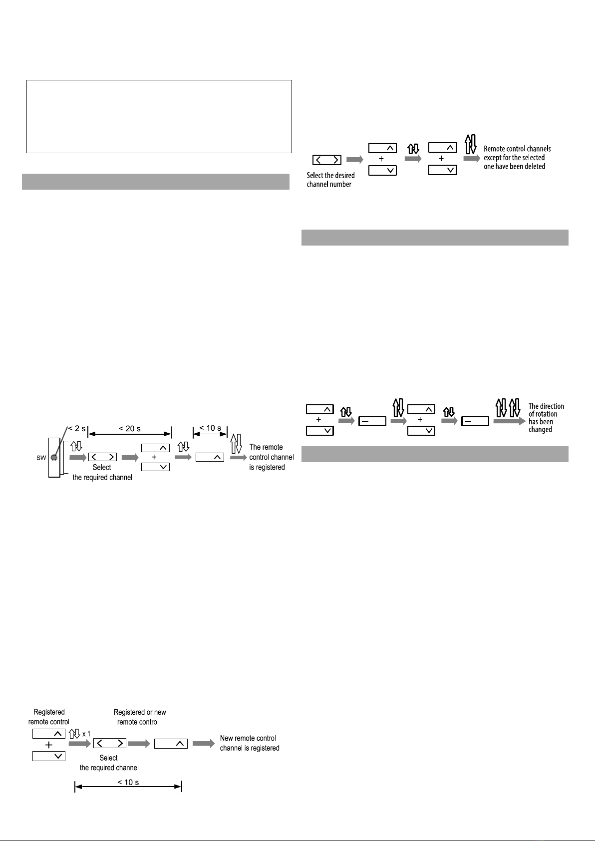
3.1 Registering the first remote control
For drives received from the manufacturer or if the remote control is lost,
the remote control must be registered using the following procedure:
•briefly press (< 2 seconds) the SW button on the drive head
–the drive makes a short up-down movement
•within 20 seconds select the desired channel on the remote control
and press the ∧and ∨keys simultaneously - the drive will make a
short up-down movement
The 20 second limit applies to all operations with simultaneous
pressing of the ∧and ∨keys.
•press the key ∧the next 10 seconds –the drive will confirm
the channel registration by making a long up-down confirmation
movement
NOTE: The procedure will erase all previously registered channels
from the drive memory. This allows the registration of a remote
control for the drive when no registered remote control is available
(new drive or case of lost / stolen remote control).
3.2 Registering another remote control / channel
When you have a previously registered remote control, further channels
of the same or another remote control must be registered without using
the SW button.
To this end:
•on the registered remote control simultaneously press the
keys ∧ and ∨–the motor makes a short up-down movement
For the next 20 seconds, the drive remains in registering mode. To
register a new channel of the same or a different remote control, proceed
as follows within that time:
•select the desired channel on the remote control
•press the key ∧ –the drive will make a long confirmatory up-down
movement
With this method, you can register any channel to any drive, but only if
you have a pre-registered remote control.
3.3 Deleting memorised channels
To delete memorised channels, proceed as follows:
•select channel on registered remote control
•press simultaneously the keys ∧ and ∨–the drive makes a short up-
down movement
•once again press simultaneously the keys ∧ and ∨–the drive will
make a long confirmatory up-down movement –all channels will be
erased except for the channel of the remote control used in the erasing
procedure.
NOTE: all remote controls and other channels of this remote
control will be deleted
.
4Change of direction of rotation
If, after pressing the key ∧the roller shutter moves upwards, the direction
of rotation of the drive is correct and you can proceed to set the end
positions.
If the direction of rotation is opposite, it should be changed as follows:
•press simultaneously the keys ∧ and ∨ on the remote control
–the drive makes a short up-down movement
•press the key (STOP) on the remote control –the drive makes a long
up-down movement
•press simultaneously the keys ∧ and ∨ on the remote control
–the drive makes a short up-down movement
•press the key (STOP) on the remote control –the drive makes 2 long
confirmatory up-down movements
NOTE: the end positions will be erased when the direction is
changed.
5Setting of end positions (EP)
Manual EP setting is not necessary, as the drive can set it automatically.
For this purpose, 3 cycles of full opening / closing of the roller shutter are
required. The drive has an overload detection function; after stopping 3
times at an obstacle (parapet, stopwatch) in the same place, it sets a zone
of increased sensitivity there. Subsequent stops in this zone will occur
with greater sensitivity –as you enter the zone, the motor slows down,
gently reaches the obstacle and stops.
After moving the drive to another window or after changing the length of
the roller shutter, it is enough to make 3 cycles of closing/opening the
roller shutter for the drive to set the new end positions
The drive starts at 100% when moving downwards, and at 50% when
moving upwards and accelerates to 100% after 2 s
The manual setting of the EP is described below.
The order in which the EPs are set is irrelevant; you can set both EPs,
only one of them or not set an EP at all.
The EPs cannot be set too close together; the drive will make a short
up-and-down movement when attempting to do so.
5.1 Setting the upper end position (UEP)
To set the upper end position (UEP):
•set the roller shutter to the desired UEP (with the ∧, ∨, ▬(STOP)
keys on the remote control
•press simultaneously the keys ∧ and ∨on the remote control
- the drive makes a short up-down movement
•press the key ∧ on the remote control –the drive makes a long up-down
movement
•press simultaneously the keys ∧ and ∨ on the remote control
- the drive makes a short up-down movement
•press the key ∧on the remote control –the drive makes 2 long up-down
movements –the UEP has been set
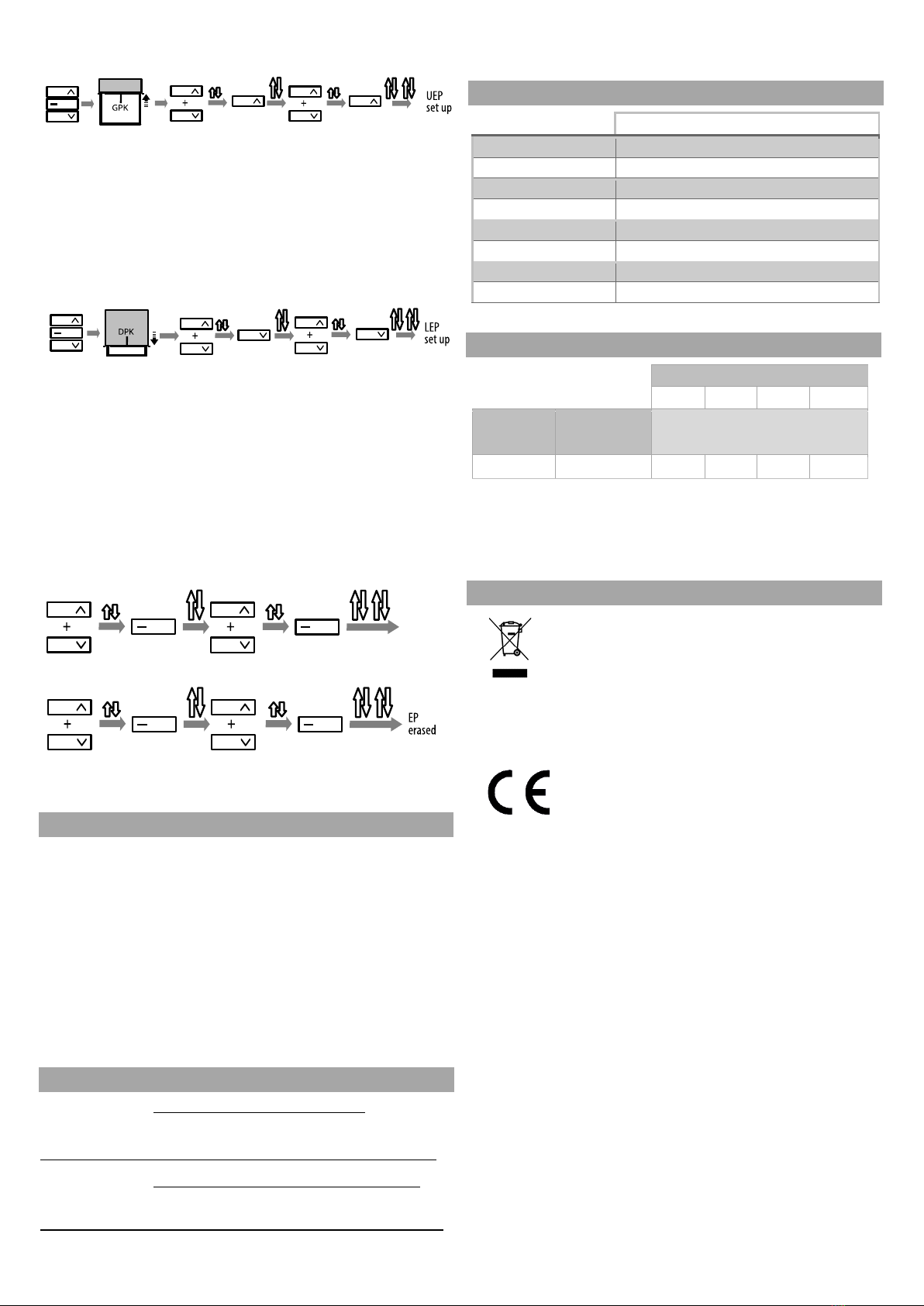
5.2 Setting the lower end position (LEP)
To set the lower end position (LEP):
•set the roller shutter to the desired LEP (with the ∧, ∨,▬(STOP) keys
on the remote control
•press simultaneously the keys ∧ and ∨ on the remote control
- the drive makes a short up-down movement
•press simultaneously the keys ∧ and ∨on the remote control
- the drive makes a short up-down movement
•press the key ∧ on the remote control –the drive makes 2 long up-down
movements –the LEP has been set
5.3 Erasing end positions (EP)
To erase end positions (EP): execute twice the procedure for reversing
the direction of rotation
•press simultaneously the keys ∧ and ∨on the remote control –the
drive makes a short up-down movement
•press the key ▬(STOP) on the remote control –the drive makes a
long up-down movement
•press simultaneously the keys ∧and ∨ on the remote control –the
drive makes a short up-down movement
•press the key (STOP) button on the remote control –the drive makes
2 long up-down movements
•repeat the above steps
ATTENTION! Pressing the SW button while the roller shutter is
moving will also delete the end positions.
6Operating instructions
6.1 Battery
The manufacturer supplies the drive with a charged battery. Once the
drive is installed, the battery is recharged with electricity from the solar
panel.
If there is a long period between purchase and installation of the drive,
the battery should be charged using a charger (sold separately by the
manufacturer). The charger should be connected to the drive in place of
the solar panel. The time to full charge is approximately 8 hours.
If the charge level is too low, the drive stops and makes 2 short up- down
movements when attempting to start.
When the need to charge the battery with the charger occurs too
frequently, check the condition of the solar panel. If thepanel is clean and
sunlight reaches it unobstructed, the battery is probably worn down.
7Troubleshooting
Problem: Motor does not respond to commands
Reason: Battery is discharged
Solution: Charge the battery
Problem: Battery requires recharging several times a year
Reason: Battery is worn out
Solution: Replace the drive
8Technical data
GM35LER-10/9
(N-10LER).
Power supply
12 DC
Torque
10 Nm
Power
21,6 W
Rotation speed
9 obr./min.
IP rating
IP 44
Operating time
100 s
Length
655 mm
Weight
1,55 kg
9Tubular motor selection table
Roller blind length
1,5 m
2,0 m
2,5 m
3 m
Rotation
Speed
Tube
diameter
Permissible roller shutter weight
for the above heights
N-10 Nm
Φ = 40 mm
20 kg
19 kg
18 kg
17 kg
The parameters given are only estimates - they depend on numerous
factors (correct installation, co-efficient of friction of the blind,
atmospheric conditions and other).
10 Handling of waste equipment
Do not dispose of with household waste. Dispose only in
specially designated areas. Households play a key role in the
recycling of waste electrical and electronic equipment.
Waste sorting, including waste equipment and batteries,
guarantees that the equipment is not disposed of with
household waste but is handed over to a designated collection point for
the recycling of waste electrical and electronic equipment.
Przedsiębiorstwo Informatyczno-Elektroniczne INEL
Sp. z o.o., ul. Mostowa 1, 80-778 Gdańsk, as the
manufacturer of the product, hereby declares that the
drive described in this manual and used in the manner
specified herein complies with the essential
requirements of the relevant EU directives, in particular Directive
2006/42/EC and Directive 2014/53/EU.
The full text of the EU Declaration of Conformity is available at the
following internet address: www.inel.gda.pl
1paneolarnego GC8005
The solar panel is designed for the application with the GM35LE-10/09
(N-10LER) drive. The panel converts solar energy into electrical energy
used to charge battery packs located inside the drive.
1Safety tips
Do not drill holes in the solar panel.
When attaching the solar panel to the shutter box,
do not use excessive force to avoid solar panel damage.
Do not cover the panel with paint.
2Installation
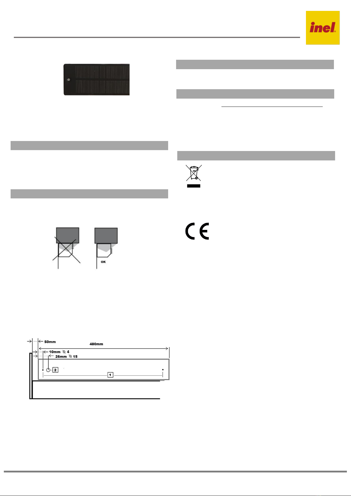
2.1 Site selection
Place the panel on the shutter box cover in the area with the highest sun
exposure.
2.2 Solar panel fixing
In order to fix the solar panel properly, please follow the steps listed
below in the following sequence:
•drill two 3 mm holes in the shutter box, as shown in the figure below,
to attach the solar panel and a 15 mm hole to insert the cable, smooth
the edges of this hole.
•thread the panel cable through the hole into the box interior.
•fix the solar panel with aluminium rivets (with a diameter of 4.0mm)
or screws (max length 15mm) in both drilled holes, taking special care
2.3 Electrical connections
The connector, which is terminated by the solar panel cable, should be
connected to the socket located on the motor cable. The wires should be
attached to the side of the box so that they do not come into contact with
moving parts.
3Cleaning
Keep the solar panel clean. Use clean water and a soft cloth for cleaning.
Do not allow the panel to be covered with leaves or snow.
4Troubleshooting
Problem: Battery requires recharging several times a year
Reason: Solar panel is insufficiently illuminated
Solution: Remove obstructions, clean the panel.
Reason: Solar panel is faulty
Solution: Replace the solar panel
5Handling of waste equipment
Do not dispose of with household waste. Dispose only in
specially designated areas. Households play a key role in the
recycling of waste electrical and electronic equipment.
Waste sorting, including waste equipment and batteries,
guarantees that the equipment is not disposed of with
household waste but is handed over to a designated collection point for
the recycling of waste electrical and electronic equipment.
Przedsiębiorstwo Informatyczno-Elektroniczne INEL
Sp. z o.o., ul. Mostowa 1, 80-778 Gdańsk, as the
manufacturer of the product, hereby declares that the
drive described in this manual and used in the manner
specified herein complies with the essential
requirements of the relevant EU directives, in particular Directive
2006/42/EC and Directive 2014/53/EU.
The full text of the EU Declaration of Conformity is available at the
following internet address: www.inel.gda.pl
Przedsiębiorstwo Informatyczno-Elektroniczne INEL Sp. z o.o., ul. Mostowa 1, 80-778 Gdańsk, Poland [email protected] www.inel.gda.pl
Original Manual PL
Installation and operation manual for solar panel: 3,8W, 18V
Model: GC8005
This manual suits for next models
1
Popular DC Drive manuals by other brands

WEG
WEG CFW900 installation guide

Welcon
Welcon WEC-D048/25-FS0025-E Hardware manual

Danfoss
Danfoss VLT AutomationDrive FC 301 Programming guide

Altec Lansing
Altec Lansing HF DRIVER CROSS REFERENCE MASTER LIST Reference

HAUTAU
HAUTAU EKA 20-118 Additional instructions

Danfoss
Danfoss NEMA-3R installation instructions


Power Electronics
Power Electronics SD 500 Series manual

Parker
Parker HMR 08 Series Assembly and operating instructions

Control Techniques
Control Techniques MiniAx 60 x 5/10 manual

Danfoss
Danfoss VLT Midi Drive FC 280 installation guide

Frecon
Frecon FID-L18 Installation and user manual

Trane
Trane VarioTrane TR1 2800 Series operating instructions