Frecon FID-L18 User manual

FRECON, spol. s r.o. Hodkovická 115, 142 00 Praha 4, CZECH REPUBLIC
tel: +420-241 71 32 44-45, fax: +420-241 72 10 52 E-mail: info@frecon.cz http://www.frecon.cz
•
FRECON
FID-L18, 37, 55, 75, 110, 150, 220, 250
SPEED DRIVES
FOR
STANDARD AC INDUCTION MOTORS
0,18kW TO 2,5kW
INSTALLATION AND USER MANUAL

1
1. Introduction
•Small, light-weight and compact
•IGBT output bridge for high speed switching and low power consumption
•Motor speed control - 8 preset speed values
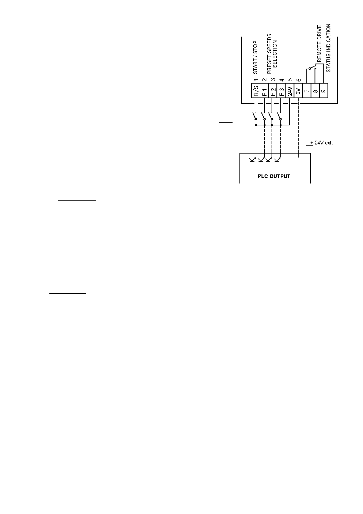
•Logic inputs for remote control
•Preset drive parameters - factory drive adjustment under special customer conditions
•FRECON TELECONTROL: remote control and indication unit
•External RFI input filter
2. General characteristics
Type: FID-L: 18 37 55 75 110 150 220 250
Nominal motor rating (kW) 0,18 0,37 0,55 0,75 1,1 1,5 2,2 2,5
Input:
Voltage 1x 230V ±10%
Nominal motor rating (kW) 2,6 4,4 6,1 7,0 9,6 12,2 17,5 20,0
Frequency 47 ÷63 Hz
Output:
Voltage 3 x 0 ÷input voltage
Frequency 8 preset values
20,25,30,35,40,44,47,50Hz
acceleration/deceleration between
preset values - 5Hz/s
Apparent power (kVA) 0,6 1,0 1,4 1,6 2,2 2,8 4,0 4,5
Overload 150%, 30 sec
Nominal current (A) 1,4 2,4 3,0 4,0 5,5 7,0 10,0 11,3
Modulation PWM - 18kHz
V / f - characteristic square - law
Control:
logic inputs - control switches or PLC outputs
function - START/STOP, preset speeds selection: 8 values
Protections:
low voltage, overvoltage, overcurrent, I x t, short-circuit (phase-phase, phase-earth)
Enviromental conditions:
Ambient temperature 0 ÷400C
Ambient humidity max. 90% (non condensing)
Enclosure IP 00 or IP 20 or IP 54
Design criteria:
Safety EN 61 010-1/95
Electromagnetic compatibility-emission: EN 55 011/A1,B1; EN 50 081-1, 2 (with external RFI filter)
-immunity: EN 50 082-1, 2
Dimensions: Height (mm) 180 200
Width (mm) 153 160
Depth (mm) 97 145
Weight: (kg) 1,3 2,5
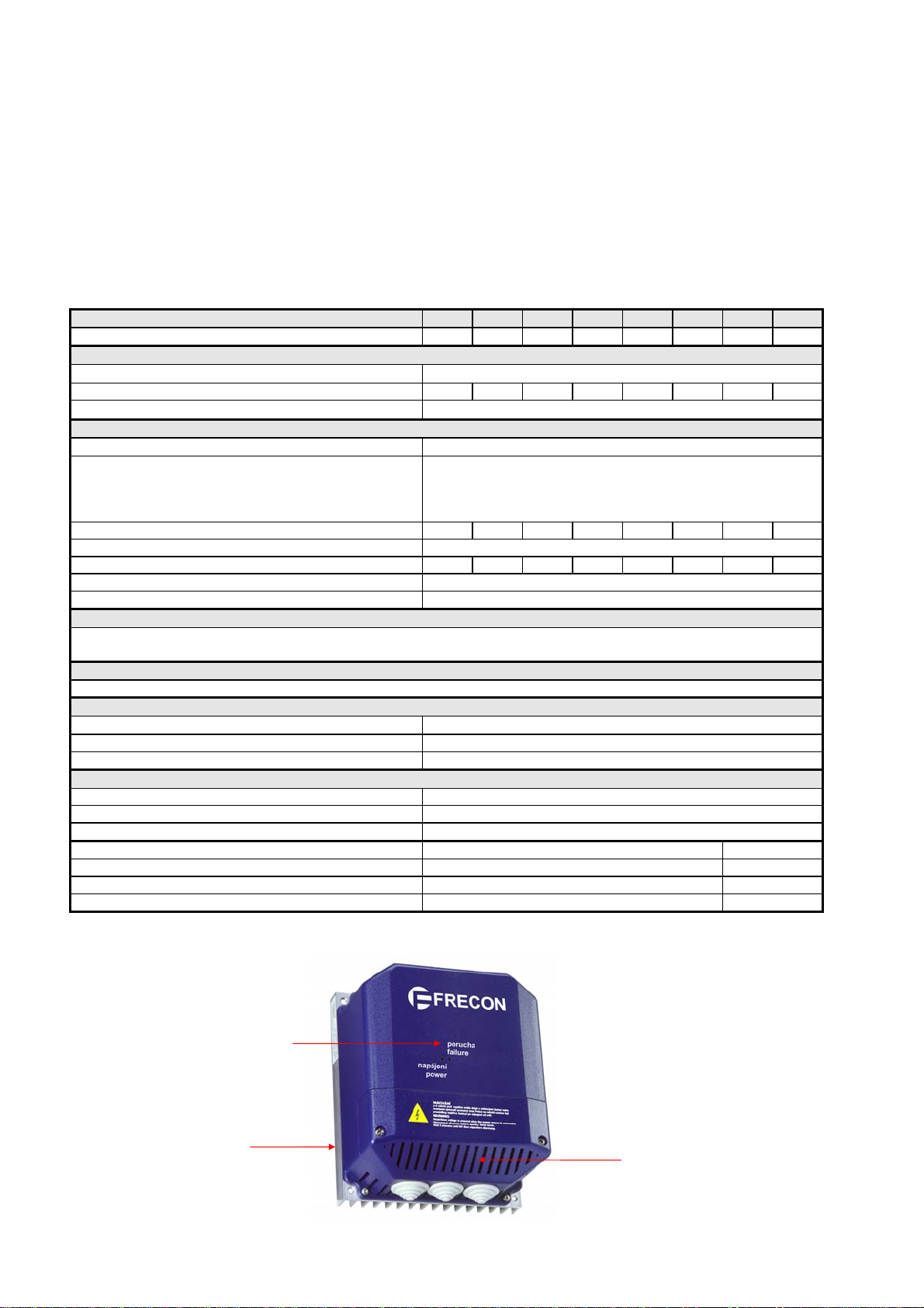
3. Description
heat sink control and power
cables lead-in
status LED indication
- power
- failure

2
4. Mechanical installation
4.1. Location
The installation must be located in a place free from dust;corrosive vapours;gases and all liquids.
Care must also be taken to avoid condensation of vaporised liquids, including atmospheric moisture.
4.2. IP rating
IP 20 or IP 00 (e.g. location in a switchboard ) or IP 54
4.3. Mounting
•The unit must be mounted vertically, and sufficient clearance must be allowed around the unit to
allow adequate flow of cooling air over the fins of the heat sink. A minimum of 50 mm is required
above and below the unit, and some clear space should also be allowed at the sides and front.
•Location within the cubicle (e.g. switchboard) without any ventilation of the air inside :
Heat can escape only by conduction through the skin of the cubicle, which is cooled by radiation to
the external air.
A minimum distance from the enclosure boundaries : 50 mm
Heat dissipation power : cca 4% of the real output power.
5. Electrical installation
SAFETY PRECAUTIONS
DANGER: The voltages present in the supply cables, the output cables and terminals,
the control power supply wiring and in certain internal parts of the drive are
capable of causing severe electric shock and may be lethal !
WARNING: Whenever the drive has been energised
;
it must be isolated before work may
continue. A period of five minutes must elapse after isolation to allow the internal
capacitors to discharge fully. Until the discharge period has passed dangerous
voltages may be present within the drive.
Persons supervising and performing electrical installation must be suitably qualified and
competent in these duties, and should be given the opportunity to study this manual before work
is started.
5.1. Power connections
CHECK THAT
•the unit is disconnected from the input power before making connections to the terminals
- AC input power circuit breaker, installed upstream on the low voltage switchboard, is in "off"
position
5.1.1. Connection procedure
•FOR PROTECTION OF LIFE AND PROPERTY, EARTH WIRES SHOULD ALWAYS BE
CONNECTED FIRST !
•remove the front panel that is secured with screws
•connection cables should enter at the bottom
•connect the 1 PHASE mains supply to the terminals N;L.
•connect the motor terminals to the U, V, W terminals of the drive
•refit the front panel
NEVER CONNECT the input power to U; V; W terminals of the drive !!!

3
The layout of the power terminals and connections is shown in FIG 1.
FIG 1
5.1.2. Recommended protection devices installed upstream of the drive and cabling
Drive model FID-L 18 37 55 75 110 150 220 250
fuse ratings* 6A 10A 16A 20A 25A
cable size (for 3-core)** mm
2
1,5 2,5 4
* The use slow protection devices (curve C) is recommended, because a current surge may appear at power on.
** Cable sizes are recommendations only. Cabling should conform to local codes of practice and regulations.
5.1.3. Motor connection
•No protection devices between the drive and the motor are recommended. The power connections
from the drive output to the motor may be switched, for isolation purposes;but not for control
purposes.
•Connection between the drive and the motor as short as possible are recommended to prevent
emissions from the motor cable.
If it is not possible, screened or armoured cable may be used . The screen or armour should be
connected in the same way as for standard cable (to both the motor earth terminal and the drive
earth terminal).
•Installations with long cable runs to the motor (i.e. above approx. 30 m), may need the addition of
motor line chokes to prevent nuisance tripping of the drive caused by capacitative leakage
effects.
Output voltage of the drive FRECON FID - L : 3 x 230 V !
MOTOR WINDING CONNECTION MUST BE COMPATIBLE WITH THIS VOLTAGE !
IN THE MOST CASES : DELTA CONNECTION
5.2. Motor speed
•Standard squirrel-cage ac induction motors are designed as single speed machines. If it is
intended to use the capability of the drive to run the motor at speeds above its designed
maximum, it is strongly recommended that the motor manufacturer is consulted first.
•The principal risks due to overspeeding are the destruction of the rotor by centrifugal force, or of
the bearings by vibration or heat.
•Low speed is liable to result in overheating of the motor because the effectiveness of the internal
cooling fan reduces in proportion to the square of the reduction of speed. Motors should be
equipped with thermistor protection, and if full benefit of the use of low speeds is to be gained
from a variable speed drive it may be necessary to arrange additional cooling for the motor.

4
5.3. Control connections
5.3.1. Connection procedure
•remove the front panel that is secured with screws.
•for control connections use cable of 0,5 mm2screened
•connection cable should enter at the bottom.
•connect screen to earth at the drive only .
•connect control cable to terminals
(connections are shown in FIG 2).
•refit the front panel
FIG 2
NOTE : always segregate control and power cabling !
5.3.2. Specifications of control inputs and outputs
Complete isolation between control and power electronic circuits.
•Logic inputs
- run/stop : control switch or PLC output
- preset speeds selection : control switches or PLC outputs
(Three binary preset speed inputs select 8 preset speeds)
Input voltage : min : 15 VDC Input current : cca 8,5 mA (24 VDC)
nominal : 24 VDC
max : 30 VDC
Input signal delay : max 5 ms
•Logic output
- drive status : volt-free change-over relay contact - 250 VAC ;8 A
6. Drive status indication
6.1. On the front panel of the drive
•LED "POWER" (red): input voltage is present, all internal voltage levels are correct
•LED "FAILURE" (red): internal or external trip (e.g. overvoltage;overcurrent;short-circuit ... )
the drive is stopped (disconnected from the load)
6.2. Remote indication
•Volt-free change-over relay contact
Control terminals : 8- normally open
7 - common
9- normally closed
Relay energised when : drive healthy
Relay de - energised when : power off or drive tripped (disconnected from the load)
7. Operating procedures

5
CHECK THAT :
* the motor rating is compatible with the drive rating
* the motor winding connection is compatible with the drive output voltage
(refer to chapter 5;section 1.3.)
* AC input power circuit breaker of the correct rating is installed upstream on the low
voltage
switch-board (refer to chapter 5, section 1.2.)
* the drive is firmly attached in an upright position and is properly ventilated
7.1. Procedure I -remote (external) control without using TELECONTROL - remote control unit
•connect the control cable to terminal board (shown in FIG 2)
•put the AC input power circuit breaker in "ON" position - the red "POWER" light goes on.
In the event of a fault;the red "FAILURE" light goes on.
7.1.1. Speed control
Three binary preset speed inputs (control terminals F1;F2;F3) select 8 preset speeds.
change-over
switch
position
(telecontrol)
F1 F2 F3
output frequency
1 0 0 0 20 Hz
2 0 0 1 25 Hz
3 0 1 0 30 Hz
4 0 1 1 35 Hz
5 1 0 0 40 Hz
6 1 0 1 44 Hz
7 1 1 0 47 Hz
8 1 1 1 50 Hz
NOTE : 0 = external contact open (disconnecting 24V DC from the terminal)
1 = external contact closed (connecting 24V DC to the terminal)
Acceleration/deceleration between preset values : 5 Hz/s
7.1.2. "Run/stop"
•connect 24V DC to the terminal 1(control switch or PLC output) :
The motor will start and run up to the set speed.
•disconnect 24V DC from the terminal 1:
The motor will coast to a stop.
7.2. Procedure II -remote (external) control, using TELECONTROL - remote control unit
•connect the control cable to the terminal boards at the drive and the TELECONTROL
(shown in FIG 4)
•put the AC input power circuit breaker in "ON" position - the red "POWER" light goes on.
In the event of a fault;the red "FAILURE" light goes on.
FIG 4
FIG 3
1
2
3
4
5
6
1
2
3
4
5
9
6
7
FRECONFID-L
TELECONTROLFID2/ALT-P2
7
8

6
7.2.1. Speed control
•rotary change - over switch : preset speeds selection (shown in FIG 3)
7.2.2. "Run/stop"
•change-over switch : function (refer to chapter 7;section 1.2.)
7.2.3. Drive status indication
•LED "FAILURE" (red) : internal or external trip;the drive is stopped (disconnected
from the load)
8. Reset of the drive after a trip signal
Disconnect the drive from the supply for the short time and reconnect.
NOTE : restart of the drive ( "START" signal activation ) is recommended when the motor is stopped !
9. Options
9.1. FRECON TELECONTROL - remote control unit
•fault LED indication
•run/stop : change-over switch
•speed control : rotary change-over switch
•dimensions : 110 x 80 x 55 mm (h x w x d)
•mounting : externally anywhere convenient at a distance
permitted by a maximum cable length of 50 m from the
drive to the
TELECONTROL
9.2. EXTERNAL RFI FILTER
To conform to EMC standards, external RFI-filter is necessary to use.
RFI - filter is located in the separate cubicle with enclosure IP 44 or IP00 (on request) or IP20
Dimensions:
•EMC emission according to EN 50 081-1, ČSN EN 55 011/B1:
FID-L18 ÷ 75 : - enclosure IP00: 92 x 60 x 49 mm
FID-L18 ÷ 75 : - enclosure IP44: 160 x 90 x 70 mm
FID-L110 ÷ 220 : - enclosure IP00: 92 x 60 x 56 mm
FID-L110 ÷ 220 : - enclosure IP44: 160 x 90 x 70 mm
FID-L250 : - enclosure IP20: 138 x 56 x 50 mm
•EMC emission according to EN 50 081-2, ČSN EN 55 011/A1:
FID-L250 : - enclosure IP20: 138 x 56 x 50 mm
9.2.1. Installation
To install the filter, follow the instructions in FIG 5
keep cables as
short as possible
2,5 mm2
FIG.5

7
The filter cubicle is necessary to install near of the drive.
NOTE: Connections must be made with the short length of screened cables. If these cables are altered in
any way the filter will operate, but compliance with any emission standard is no longer assured.
Input cable into the filter (filtered cable) and no control circuit should be run parallel to an unscreened
motor cable or unfiltered supply cable with a spacing less than 0,3 m and over a distance exceeding 1m.
9.3. Motor line choke

8
Dear user,
This manual has been designed to provide you with all the information you
need to install and use your FRECON SPEED DRIVE. Feel free to contact us for
any further information you may require concerning special applications
beyond the scope of this manual.
Please keep this manual in a safe place for future reference.
FRECON
SAFETY PRECAUTIONS
DANGER: The voltages present in the supply cables, the output cables and terminals,
the control power supply wiring and in certain internal parts of the drive are
capable of causing severe electric shock and may be lethal !
WARNING: Whenever the drive has been energised
;
it must be isolated before work may
continue. A period of five minutes must elapse after isolation to allow the internal
capacitors to discharge fully. Until the discharge period has passed, dangerous
voltages may be present within the drive.
Persons supervising and performing electrical installation must be suitably qualified and
competent in these duties, and should be given the opportunity to study this manual before work
is started.
TESTED
Commited to quality, FRECON individually test each FRECON SPEED DRIVE to
ensure reliable performance for the user. All units have passed FRECON´S quality
control standards and conform within tolerance to the enclosed specifications.
ENTIRE CONTENS COPYRIGHT FRECON s.r.o. ALL RIGHTS RESERVED, REPRODUCTION IN WHOLE or IN PARTS WITHOUT PERMISSION IS
PROHIBITED. FRECON FID-L IS a PRODUCT OF FRECON.
This manual suits for next models
7
Table of contents
Other Frecon DC Drive manuals
Popular DC Drive manuals by other brands

Omron
Omron SYSMAC CXONE-ALC-EV2 Series Operation manual

Pacific Scientific
Pacific Scientific 6430 Installation & hardware reference manual

ST
ST X-CUBE-SPN12 user manual

SEW-Eurodrive
SEW-Eurodrive MOVIMOT D EtherNet/IP Compact manual

ABB
ABB MicroFlex e150 Quick installation guide

TKM
TKM 3424 Fitting instructions