Inel YYGL35E-10/17 User manual

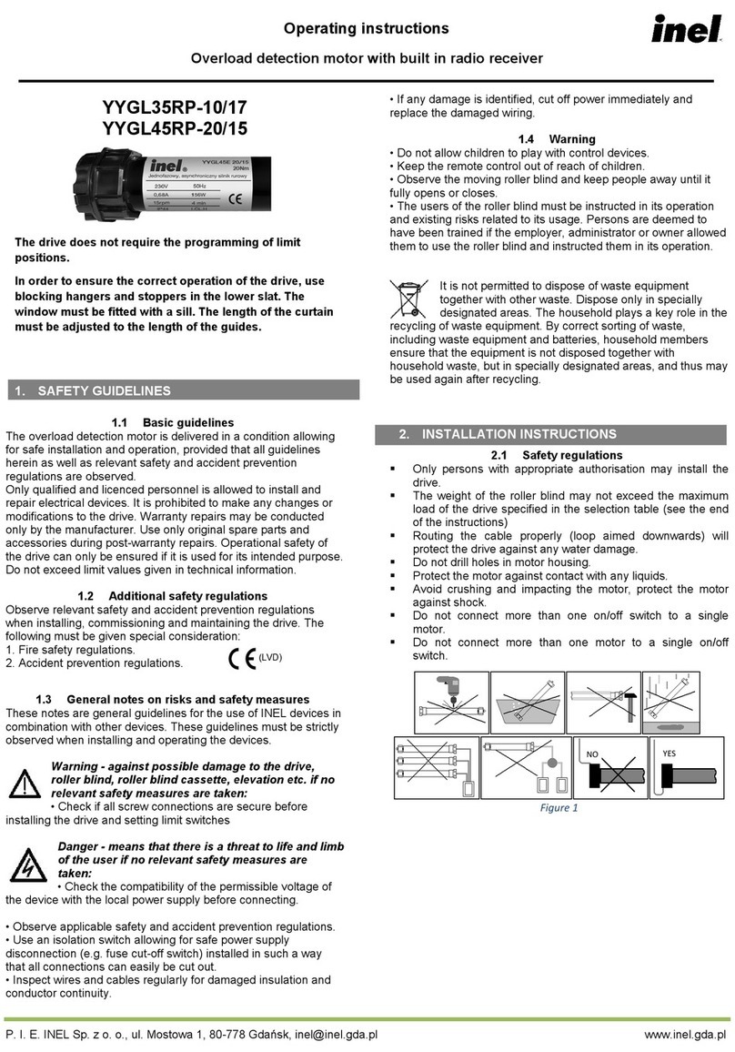
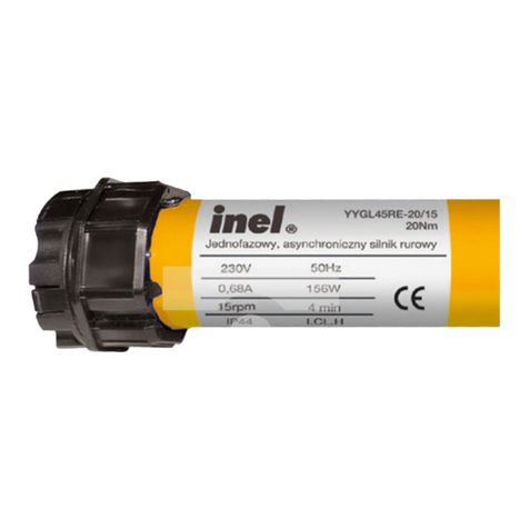
YYGL35E-10/17
YYGL45E-20/15
DRIVE WITH OBSTACLE DETECTOR AND ELECTRONIC END STOP SWITCHES
Basic guidelines
Instructions for installation, programming and operation
The tubular motor YYGL35E-10/17/YYGL45E-20/15 with obstacle detection can be safely installed and used provided
all of the following instructions of installation and use as well as obligatory health and safety regulations are adhered to.
The installation and repairing of electrical equipment should be carried out only by persons with appropriate legal
qualifications.
Reconstructing or making changes to the tubular motor YYGL35E-10/17/YYGL45E-20/15 with obstacle detection is
forbidden. During the guarantee period repairs only the manufacturer may carry out repairs. Even after the guarantee
period has expired only original parts and accessories may be used.
The guarantee is only valid when the tubular motor YYGL35E-10/17/YYGL45E-20/15 with obstacle detection has been
used in accordance with the manufacturer’s instructions. The boundary values given in the technical specifications must
NOT be exceeded under any circumstances.
Supplementary safety regulations
When installing, using or carrying out maintenance work all binding health and safety regulations should be followed.
Particular attention should be paid to the following:
1. European standards
2. Fire regulations
3. Accident avoidance
GENERAL COMMENTS REGARDING HAZARDS AND SAFETY PRECAUTIONS
The following comments serve as general guidelines to the application of INEL drivers with other devices.
These guidelines must always be adhered to when installing and operating these devices.
Warning –this signal warns of possible damage to the control system or other equipment if appropriate
safety measures are not taken.
Before installing the control system and setting the end switches check all bolt connections are properly fastened.
Danger –this signal indicates danger to the user’s life and health if appropriate safety measures are not taken.
Follow all health and safety regulations relevant to the equipment (e.g. gates, roller blinds)used.
When changing fuses the equipment must be first disconnected from the mains, the fuses changed and only then
may the equipment be reconnected to the mains.
INEL equipment connected to the mains beyond a building’s safety fuse system needs to be installed with its own
safe disconnecting devices (e.g. safety fuses and safety switches) in such a way so as to ensure that all the units
may be easily and safely cut off from the mains.
Electric wiring and cables should be regularly checked to ensure the insulation is intact and there are no breaks in
the wire.
If any damage to the wiring is found, the unit should be immediately disconnected from the mains and the
damaged wiring replaced.
Before connecting any equipment, one should first make sure that it is adapted to be used with the local voltage in
the mains.
PERSONAL SAFETY WARNING
Do not allow children to play with any of the control devices.
Keep all remote control devices out of the reach of children.
Observe the opening or shutting of the blinds, shutters, awnings or gates and ensure all persons stand clear
until the operation is completed.
Control system operators need to undergo preliminary instruction and training and also be made aware of all the
potential dangers that can be encountered. A person should only be authorized to use the control system only
once the employer, administrator or owner is satisfied that that person has been properly instructed.

Assembly instructions
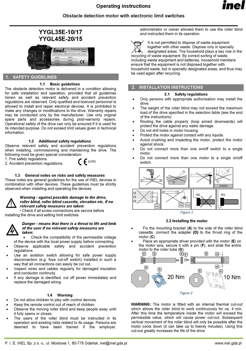
Safety rules:
This product should only be installed by qualified personnel.
1.
Roller blind weight cannot exceed the maximum working load of the
drive, as expressed in selection table.
2.
Appropriate positioning of the cable protects the drive from being
damaged by water.
3.
Do not puncture the engine along its entire length.
4.
Protect the engine from contact with liquids of any kind.
5.
Protect the engine from crushing, falling and do not subject it to shock.
6.
Do not connect more then one manual switch to one motor.
Motor
assembly
Fix mounting bracket (
A)
to the side of the roller blind, connect adapter with engine drive ring (
C/D
).
Place the special driver attached to the engine (
E
) on the engine axis and secure with clip (
E/F
). Insert the
entire engine into the winding pipe (
G
).
Connect winding pipe and dricer with screws or rivets (
H
).
CAUTION!
Engine is equipped with internal thermal switch, which allows for about 4 minutes of constant work.
Afterwards the temperature within the engine exceed the maximum limit value, which will result in power
supply being cut off. Roller blind can be moved again once the engine has cooled off (which might take
several minutes). This solution serves to prolong the life of the drive.
Electrical connection
Switch the power off prior to making electrical connections of any sort.
Yellow/ green (PE protective)
Blue (N neutral)
Brown (L1 phase up direction)
Black (L1 phase down direction)
Grey (disconnected)
INCORRECT ASSEMBLY MAY RESULT IN UNCONTROLLABLE STOPPING OF THE MOTOR
Conditions necessary for proper functioning of obstacle detector:
1.
Use of the special driver attached to themotor.
2.
Free movement of roller armouring in guide rails and casing under gravity; the motion cannot
be disturbed (abrasion of roller casing, mosquito net,etc.)
3.
Weighting down the lower strip (with band iron, forexample).
4.
Connecting the opposite sides of the driver to the winding pipe with two screws/bolts/rivets.
No need for locks or stoppers.

1. Setting the end positions of the drive
PROGRAM THE TOP END POSITION FIRST, THEN THE BOTTOM END POSITION.
Upon installation, the drive performs a short up and down motion, which signals lack of end
positions.
While programming the end stop values, the engine will start, then stop for a moment, then continue its motion.
There are two methods of programming end positions:
A.
Manual
a.
Check if the directions of the roller blind movement correspond to the directions indicated on
the manual switch. Place the roller blind in the middle position.
b.
Tense the roller armour by pulling the bottom slatdown.
c.
Simultaneously press and hold the '▲' and '▼' buttons until the motor makes short move
up –down. (Start of setting end positions).
d.
Press and hold the '▲' button. The roller blind will move upwards. Stop it before the desirable
top end position by releasing '▲' button. Using '▲' and '▼' buttons set end position.
e.
Simultaneously press and hold the '▲' and '▼' buttons for about 5 seconds, the motor will
makes short move down –up. (Confirming the top end positions)
f.
Press the '▼' button, the roller blind will move downwards.
Motor will automatically stop on the
windowsill.
•
Position can be changed by pressing '▼' button again. Repeat for desirable shutter
position.
g.
Confirm the bottom end position by simultaneously pressing and holding the '▲' and '▼'
buttons for about 5 seconds, the motor will makes short move up –down.
h.
Press the '▲' button. The motor will move upwards and stop at the top end position.
i.
Motor will perform a short up and down movement. With this the programming is finished
.
B.
Automatic (requiresstoppers)
a.
Check if the directions of the roller blind movement corresponds to the directions indicated
onthe manual switch. Place the roller blind in the middle position.
b.
Tense the roller armour by pulling the bottom slatdown.
c.
Simultaneously press and hold the '▲' and '▼' buttons until the motor makes short move
up –down. (Start of setting end positions).
d.
Press and hold the '▲' button. The roller blind will move upwards and stop at the upper
stopper. If it stops earlier, press the '▲' button once again.
e.
Press the '▼' button. Motor will perform a short down –up movement. The motor will
register the new top end position and move downwards
, it automatically stops on the
windowsill.
•
Position can be changed by pressing '▼' button again. Repeat for desirable shutter
position.
f.
Press the '▲' button. Motor will perform a short up –down movement. The motor will
register the bottom end position, move upwards, and stop at the top end position.
g.
Motor will perform a short down –up movement. With this the programming is finished.
2. Return to initial settings (end positions deletion)
Simultaneously press the '▲' and '▼' buttons for about 10 seconds, motor will perform two short
up –down movements. The drive will return to the initial settings. Following this procedure you will need
to re-program the end positions.

3. Obstacle detection.
Before setting end positions the motor detects only low rotation from overload. Obstacle detection function is
active after setting both end positions.
For downwards movement the motor will stop and go up for a distance of about 25 % of shutter length.
In case of blockade the roller shutter in upwards direction after detecting lowering of rotation the motor will
stop and go downwards to release tension.
While starting movement from upper end position obstacle detection system will work with a delay of
half/one/one and a half spin of a motor. This parameter can be change by
simultaneously pressing the '▲'
and '▼' buttons and then the ▲ to increase or ▼ to decrease. The motor will make from 1 to 3 moves
depending on the value, one=half, three= one and a half. (After setting end positions).
Obstacle detection function is active to place where the motor automatically stopped during setting bottom
end position (point B.e). Below that point obstacle detection function is not active.
4. Troubleshooting.
Problem
Couse
Solution
Motor do not react to
commands
Thermal protection worked
Wait from 10 to 20 minutes
Too quick change of directions
Wait about 5 seconds between releasing and
pushing button
Gaps between slats
Clearance between winding pipe and
driver
Connect winding pipe and driver with screws
Lockups of armour in guides
Check guides of shutter and slats
Self-stopping of
motor
Lockups of armour in guides
Check guides of shutter and slats
Motor do not detect
obstacles
End positions set in wrong order
Return to initial settings and set end positions
Moving of end
positions
Sliding of crown in winding pipe
Match winding pipe to crown
Mechanical malfunction
Change motor
P.I.E. INEL Sp. z o.o. www.inel.gda.pl
ul. Mostowa 1 inel@inel.gda.pl
80-778 Gdańsk March 2016
This manual suits for next models
1
Other Inel Engine manuals
Popular Engine manuals by other brands

Briggs & Stratton
Briggs & Stratton 120000 Operator's manual
Saito
Saito FG-17 Owner's operating instruction manual
BBT
BBT BBT-JD420 owner's manual
O.S. engine
O.S. engine FS-200S Owner's instruction manual

Vittorazi Motors
Vittorazi Motors Easy100 owner's manual
Bock compressors
Bock compressors HA6 Assembly instructions
Vanguard
Vanguard 490000 Operator's manual
Oriental motor
Oriental motor US Series operating manual
Vanguard
Vanguard 610000 Operator's manual
Oriental motor
Oriental motor K Series operating manual
Ebmpapst
Ebmpapst M3G112-GA53-72 operating instructions
BLACKHAWK!
BLACKHAWK! Talon 190 3.0 Engine Guide and Maintenance Manual

