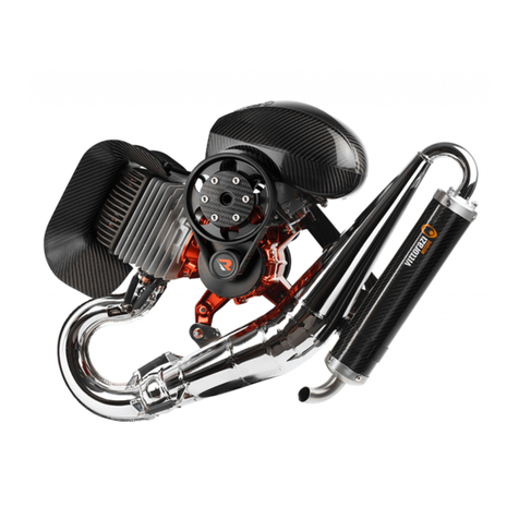
Vittorazi Motors Easy100 User manual

Vittorazi Motors
Passion lives here
Passion lives herePassion lives here
Passion lives here
Owner’s manual
Last update, October 2007
Model: Vittorazi
Easy100
Model: Vittorazi
ly100evo
All the indications writes in the charts of this manual will be underlined with the green color for
the model Easy100 and with the red color for the Fly100evo.
Address: street Roma, 182. Montecosaro 62010 (MC). Italia
Tel/Fax: +39733 866585
Commercial e-mail : info vittorazi.com
Technical support e-mail: matteo vittorazi.com
Skype: vittorazi.motors
Web-site: www.vittorazi.com

2
Index
1.0 Introduction
2.0 Warning
3.0 Installation engine components
3.1 Exhaust pipe
3.2 Rubber mountings
3.3 Air-box
3.4 Ignition coil and spark-plug
3.5 Electric installation
3.6 Gasoline tank and pipe
3.7 Throttle controller
3.8 Pull starter Easy100/ ly100evo
3.9 Choice of propeller
3.10 Accessories
4.0 Get ready for the use
4.1 Propeller mounting
4.2 uel
4.3 Starting and turning off
4.4 Warm-up
4.5 Carburetor adjustment
4.6 Break-in
5.0 Normal operation
5.1 Discovering new horizons
6.0 Specifications and technical data
7.0 Maintenance
7.1 Ignition coil and spark-plug
7.2 Check and cleaning carburetor
7.3 Reed valve
7.4 Gaskets
7.5 Exhaust silencer
7.6 Rubber mountings
7.7 Pull starter ly100evo
7.8 Pull starter Easy100
7.9 Electric starter
7.10 Reduction drive Easy100
7.11 Reduction drive ly100evo
7.12 Piston, cylinder, head
7.13 Crankshaft, crankcase and bearings
7.14 lywheel and ignition timing
8.0 Charts of maintenance
9.0 Tightening torque and special tools
10.0 Spare parts
11.0 requent asked questions - AQ
12.0 Warranty
12.1 Registration of the warranty
12.2 Limited warranty
12.3 Warranty coverage
12.4 Warranty coupon
13.0 Contacts

3
1.0 Introduction
Congratulations for having chosen a fine engine product Vittorazi.
Before passing to the installation of the motor, read this manual carefully.
With this manual we will try to give our knowledge to your service, teaching how to use
motor, providing you the necessary information for installation and maintenance, besides
we will indicate you the situations of danger, with our due suggestions to be able to
avoid them. When you will receive the motor, it will already have overcome a test of 15
minutes in the factory, verifying the operation of all the components and the operation
to every speed. All the engines Vittorazi are tested before the delivery.
If just one parts of the manual won’t be completely understood or in the case which the
manual won't be clear or exhaustive, for uncertainties, questions, to analyze or to
resolve a problem with our help, we invites you to directly contact the authorized dealer
or directly the Vittorazi.
You include in the claim the serial number XXXX of the motor that you find under the
system carburetor, some photos if you think will be necessary.
You find the direct contacts of the factory in the first and in the last page of this manual.
The Vittorazi reserves the right to change in any moment without warning, sketches,
specifications, component, details of the motor, in relationship to the model in
production without incurring in some obligation.
The reliability, the performances and the duration of your motor will also depend from
your knowledge and the way of using it.
During this manual will be underlined: in the red panel the situations that can lead you
to a serious danger; in the blue panel, suggestions or advice that have not to be
underestimated.
Attention, danger, risk
Advice, suggestion, notice
In the present photos/picture of this manual:
the arrows of green color will have generic indications specified in the inherent
paragraphs
the arrows of blue color will indicate to add lock tight medium strength
the arrows of brown color will indicate to add some grease
the arrows of black color will indicate to add sealing paste, resistant to high
temperatures (up to 500-600°C).

4
2.0 Warning
•It needs to be conscious that the motor can stop, have a breakup or to go off in any
moment. This could lead a crash to the ground or a landing in hostile areas with
possible damages/death of the pilot or other people. The ultralight moved by this
motor must fly in permitted spaces to it, not to fly above a crowd of people,
inhabited centers, zones that have difficult or void landings, not to fly above zones
of water or where is possible to drown. It always needs to have in mind that the
motor can go off or breakup, therefore to consider a possible landing of emergency
for every situation.
•This manual describes the motor. or its installation, use and control, you compare
also the attached user manual of the ultralight: Paramotor, Mosquito or Trike...
If used in other applications, cannot be guaranteed the correct operation.
•This motor is not certified. It is not a motor with guarantees or aeronautical
certifications. Its construction is destined to experimental and not certified
aircrafts.
•Some zones for particular atmospheric conditions as pressure, temperature, damp
can bring to a different operation of your motor. Before beginning every flight, you
test on the groud the motor and verify that it doesn't have an anomalous behavior.
•Start the engine in a plain surface, free from stones, sand or small parts that could
be aspirated by the propeller. Be sure that the flow of air pushed by the propeller
not lead damage to anybody. In any moment the motor is running (testing on the
ground, take-off, landing) watch out that nobody draws near to the propeller in
rotation. A good safety distance is 50 meters for all directions of projection of the
propeller and 20 meters for the others directions.
•Not use the motor that has not followed a correct maintenance or not correctly
been used in the time or if you know that is not under perfect conditions.
•The use of not original spare-part and not recognized by the Vittorazi, can make
the motor dangerous and immediately hands term to the validity of the warranty.
Vittorazi doesn't assume any warranty for that motor that are used with not
original parts or not recognized, modified or that have had an improper use.
•Changes not authorized to the motor, to the reduction, to the propellers can reduce
safety and reliability of the aircraft. In the case you have to intervene on the motor
we invite you to compare this manual with the help of your dealer Vittorazi and
follow it as reference.
•Before every use or test, check the conditions of the propeller and the tightening of
bolts of the propeller. If the propeller has received a hit and is damaged you avoid
to use or to turn on the motor. This can lead to an explosion of the propeller in
rotation or to strong vibrations that will revert in the motor with possible
consequent breakups, loss of tightening of the bolts or strong usuries of
components.
•
Do never use the motor without propeller or without reduction drive group. This
motor has been projected for a determined and contained number of turns.
Without propeller or reduction drive, the motor reaches a number of turns for
which has not been calculated. In few second there is risk of explosion of the
motor.

5
3.0 Installation engine components
The chapter or paragraph is reserved to the manufacture, dealer or center assistance
Vittorazi. If you are our collaborators, we invite you to write to our e-mail address and
get the integral version of the manual.
4.0 Get ready for the use
4.1 Propeller mounting
Be sure to possess a suitable and guaranteed propeller by Vittorazi for your motor.
Attention: the propeller can be mounted in two opposite position in comparison to the
reduction drive, which only one is correct. Ask to the authorized dealer or to the
instructor, if you are not certain for the assemblage of the propeller.
Model Easy100: rotation propeller clockwise, considering the back view
(same view of the picture 4.1).
Model Fly100evo: rotation propeller counterclockwise, considering the back view.
Push the propeller against the reduction drive, untill to insert it completely. Now gently
screw the bolts up to the end. Be sure that the bolt are proper for the propeller,
therefore the threads of the bolts are inserted at least 10mm in the hub. Now to tighten
the bolts of the propeller trying to get the same pressure on every point, picture 4.1.
Not do exaggerate with the pressure on the bolts, there is a risk to crush the propeller, if
in wood.
Have a maximum pressure of 4 -5 Nm, if the propeller is in composite carbon.
Propeller in wood: once tightened the propeller, it is opportune to check that the pich of
the two blades is identical. If there is a considerable variation among the two blades,
this difference can be compensated through the pressure of the bolts.
If you don’t know this method of balancing, ask to an authorized instructor or dealer.
Check the tightening of the wood propeller every 3 hours of flight and repeat the
balancing.
4. / tightening propeller bolts
In the case of a broken propeller, we invite you to purchase from a Vittorazi dealer, the
same propeller for measure and profile, guaranteed from the factory.

6
It will be enough to remember measure, material of the propeller and model of the
motor.
The use of a not conform propeller or the use of a propeller Vittorazi united to a wrong
reduction ratio, brings immediately end of the warranty, see paragraph 12.3

7
4.2 uel
The motor that you are going to use is a two strokes engine. It requires for the
lubrication an established percentage of oil/gasoline. When at the gas pump, always
choose gasoline unleaded 95 octanes.
The percentages will be pointed out in the following paragraphs, "break-in" 4.5 and
"normal operation" chapter 5.
The gasoline is an extremely inflammable and explosive substance. When you prepare
or in every moment you are close to the fuel (gasoline and oil), not smoke, not
provoke sparks or flames. Never fill the tank of your aircraft when the motor is
running. Position the tank of the fuel before starting the motor at least 10 meters.
During the operation of decanting, mixing, filling, choose an open place, ventilated, clean
and away from dusts, sand, grass and everythings that can obstruct the passage of the
gasoline. If possible while filling the tank of the aircraft, filter the mixture. Be sure that
the tank for the transport gasoline, filter and funnel, is perfectly always clean.
We advise only oil of good quality certified and full synthetic (no oil semi-synthetic, no
mineral oil).
We recommend the use of the following types of oil, already tested with success on our
motors: Motul 600, Castrol TTS, Valvoline Racing 2T.
Avoid mixtures prepared by the gas pump. A mixture had been prepared from 2-4 weeks
and left in a tank could separate (oil and gasoline), loosing the characteristics of
lubrication even if shaked before the use. Avoid to prepare a big quantity of mixture,
when you are already conscious to use only a part of it. Avoid use plastic tanks and
consider it as containers to transport, not left to deposit the mixture for days in the
plastic tanks. We dissuade the addition of liquids that increase the number of octanes.
Problems to the motor owed to a lack of oil in the gasoline or for a wrong mix of oil or
for lack of cleaning of the gasoline, are not recognized in warranty. See paragraph 12.3.

8
4.3 Starting and turning off
In the first starting of the engine and every time the gasoline piper remains without fuel
(tank, pipe, primer bulb and carburetor), will need to fill the circuit before starting the
motor. To do that, it is necessary make pressure on the primer bulb of the gasoline and
at the same time, with care on the valve of the carburetor (indicated with the number 6
in the following picture 4.5) up to the filling of the pipeline. It will be easy to see through
a transparent pipeline the gasoline that enters into the carburetor. For a good starting of
the engine when the circuit is empty or the motor is cold, need to enter just a few of
gasoline in the carburetor. This small quantity of gasoline, will work as starter/choke to
the motor. Attention if the quantity of gasoline that you push with the pomp to the
carburetor is excessive, there is the risks to flood the motor, even then to damage the
pull starting.
The best starting of the motor Vittorazi is gotten without throttle or with a minimum of
throttle. If the circuit of fuel is on pressure and the motor is warm, it won't be necessary
to make pressure on the primer bulb and valve.
Always watch out for the propeller during the starting and for whom could be
nearby. Many accidents happen before going to flight. On every test or warm-up,
we suggest to always wear the paramotor on your shoulder, to fast the harness,
then to turn on the engine with the pull or electric starter, ready however with
the killing button to stop the motor in every moment.
Important: often verify that the killing button is working. Sometimes the killing
buttons can get jammed or during the time can stop working.
4.4 Warm-up
You softly get throttle in the first 30 seconds allowing to stabilize the carburetor and the
motor. Now you increase the number of turns (thin to 1/4 around of throttle) and let
warm-up the motor for 2-3 minutes to this constant speed. Finally get the motor for
some second (15-20 seconds) at full throttle. Now your motor is ready to the flight.
These 3 minutes of warm-up also have to be dedicated, thanks to your attention, to
understand if the motor has some anomalous behaviors, if there are unexpected
vibrations or noises not desired.

9
4.5 Carburetor adjustment
4.5.1 A simple and fast control
Don't have any experience or affinity with the motors?
Don’t worry, you follow step by step what we tell you in this paragraph.
From years our ambition is to furnish a simple product and accessible to everybody,
trying to get simple and effective solutions for who doesn't have experience of
adjustement of motor.
When you receive the motor, it has already pass a test of 15 minutes in the thrust-bench
of the factory, verifying the operation, the assemblage and the optimal carburetor
setting.
Chart 4.5
Carburetor setting
Vittorazi Easy 00 Vittorazi Fly 00evo
Screw L from 1/4 to 1/3 of turn from 1/4 to 1/3 of turn
Screw H from 1+1/8 to 1+1/4 of turn from 1+1/8 to 1+1/4 of turn
Idle RPM 2.500-2.700 RPM 2.000-2.200 RPM
In the chart 4.5 are suitable the regulations L and H of the motor in the standard
positions. These regulations guarantee the modularity of the motor, the operating
temperature and the correct lubrication of all the organs of the motor.
4.5 / carburetor
1. Screw L or Low speed
2. Screw H or High speed
3. Screw of the throttle, open the butterfly
4. Pressure plug
5. Lever of butterfly
6. Valve for the first filling of the carburetor

10
If you choose to verify the carburetor setting proceed in this way: close completely the
screw L and H and then exactly open them with the standard setting. Remember: a
strong pressure (tightening) on these screws can irremediably damage the carburetor.
A simple verification of the carburation can be effected, following these indications.
After having started the motor in safety and warmed-up for some minutes (see
paragraph for starting and warm-up) can be done in the ground a control of the
carburation.
- The motor has to maintain a constant idle and not to have the tendency to go off or to
flood.
- When you pull the throttle fastly from the idle rpm, the motor has to immediately
answer without going off or a lack of power.
- Simulating a cruise flight (about 1/4 or 1/3 of throttle), the motor will have to answer
with a regular thrust, smooth and not with hiccups or jumps of power.
- With max speed or max number of rpm (full throttle), the thrust has to be constant.
Attention: if the carburation of the motor (the quantity of gasoline that arrive to the
motor) is poor, therefore the opening of the screw is lower in comparison to the
indications of the chart, will probably occur breakups as seizures, overheatings,
fusions of the piston, precocious usury of the components.
Problems to the motor owed to a lack of oil in the gasoline or a wrong mix oil-
gasoline, impurity in the fuel or a not correct carburation, are not recognized by the
warranty. See paragraph warranty 12.3.
A check of the carburation can be made, analysing the color of the electrode of the
spark. A first control can be done, at the end of the of break-in period, in the following
way:
- If the electrode is brown the carburation it is correct.
- If the electrode is grey or clear the carburation is poor and you have to immediately
seek the cause, with the help of an authorized dealer/instructor.
- If the electrode is dark brown color or black the carburization is rich.
Watch out for the regulation of the screw H, because if this is too closed in comparison
to suitable values, you could have damages to the motor. Any damage will occur if the
carburation of the screw H is too opened (rich). In the doubt, therefore, is everytimes
better to have a carburation rich for the screw H.

11
4.5.2 Carburation. Only skilled person.
The chapter or paragraph is reserved to the manufacture, dealer or center assistance
Vittorazi. If you are our collaborators, we invite you to write to our e-mail address and
get the integral version of the manual.

12
4.6 Break-in
A phase of break-in executed with care, improves the duration and the performances of
the motor.
The motor must be uses with attention in the first 7 - 8 hours of the break-in (25 - 30
liters).
For the period of break-in, we indicate to move the screw High to a value of 1 turn+1/4
(rotation counterclockwise for 1/4 of turn) and to increase the quantity of oil in the fuel
up to the values pointed out by the chart 4.6.1. After 10 liters of break-in the screw High
could be closed with precision of 1/8 of turn, only if the motor doesn't have smooth or
regular disbursement, as suitable in the following paragraph. From our experience we
allow to say, this will be the only time when you will have to touch the screw High.
Whenever the carburation will have a variation, it will be enough to modfy the position of
the screw Low. In these period of break-in, thanks to your intervention on the screw H
and to the increase of oil in the fuel, the motor will enjoy of a good lubrication and of a
lower temperature in comparison to the norm. The performances of the motor won't be
optimal with these regulations, but you will get a good break-in and a guarantee of
duration for the organs of the motor. The first starting of the motor must be made to
the ground (on shoulder), warm up for some minutes and pay attention to anomalous
behaviors or noises. We recommend to conclude in one day the first two phases of the
break-in. Now follow the indications of the chart 4.6.2.
Chart 4.6.
BREAK-IN
Vittorazi Easy 00 Vittorazi Fly 00evo
Screw H 1+1/4 of turn 1 +1/4 of turn
First liter 4.0% or 20:1 4.0% or 25:1
From 2 to 30 liters 3.5% or 25:1 3.0% or 33:1
Chart 4.6.2
First liter of fuel
The first phase is effected to the ground,
it will last around 15 minutes with a liter
of fuel. Alternate least, middle speed.
No max speed. Pass to the following
phase, not leaving cool the motor
completely.
From the second to the 10
th
liter of fuel
Effect flights or tests on the ground of
max 15 minutes.
Don't use the motor at the same speed
for long time, an gradual acceleration
and a release is preferable.
General check for bolts components.
From 10
th
to the 30
th
liter of fuel
If necessary close 1/8 of turn the scew
High. Always with caution also flights of
30 mins. Maintain the same percentage
of oil pointed out in chart 4.6.1. Repeat
the controls.

13
5.0 Normal operation
5.1 Discovering new horizons
At the end of the 30 liters of break-in the screw High could be in the position from 1+1/8
to 1+1/4 of turn and the percentage of oil decreased up to the values of the chart below
5.1
We advise to replace the spark-plug (with the same type and gradation) at the end of
the break-in, because the quantity of fuel and oil in excess, could have decreases
notably the duration of it.
Chart 5.
NORMAL OPERATION
Vittorazi Easy 00 Vittorazi Fly 00evo
Screw H from 1+1/8 to 1+1/4 of turn from 1+1/8 to 1+1/4 of turn
Oil 3.2-3.3% or 30:1 2.5% or 40:1
Max speed 9.300-9.500 RPM 9.300-9.500 RPM
Now the time of break-in is passed and the motor is ready to have hours and hours of
flight. Have a good fun.

14
6.0 Specification and technical data
Chart 6.0
Model Vittorazi Easy100 Model Vittorazi ly100evo
Displacement: 98.2 cc
Displacement: 98.2 cc
Stroke: 50.0mm Stroke: 50.0mm
Bore: Ø 50.0 mm Bore: Ø 50.0 mm
Piston: 2 rings, HQ graphite protect. Piston: 2 rings, HQ graphite protect.
Power: 18 hp at 9.500 RPM
Power: 18 hp at 9.500 RPM
Reduction drive: Ratio min 1/3.8 max 1/3.3.
Diretta trasmission Poly V belt.
No clutch centrifugal.
Reduction drive: helical gear drive
Ratio 1/3.3 – 1/3.65 – 1/4
Clutch centrifugal, adjustable
Max speed: 9.400-9.600 RPM Max speed: 9.400-9.600 RPM
Thrust: 58 kg with prop 125cm
Pilot up to 90-100kg
Thrust: 58 kg with prop 125cm
Pilot up to 90-100kg
EGT: 550° C EGT: 550° C
CHT: 180° C; max 210°C CHT: 170° C; max 200°C
Spark-plug: NGK BR10ES Spark-plug: NGK BR9ES
Consumption: 3.0 - 3.5. lt/h at 30kg of
thrust
Consumption: 3.0 - 3.5. lt/h at 30kg of
thrust
Weight: 11 kg, pull starter version
12 kg, electric starter version
13 kg, pull+elect starter version
Weight: 12 kg, pull starter version
12.5 kg, electric starter version
13 kg, pull+elect starter version
Propeller rotation: counterclock Propeller rotation: clock

15
7.0 Maintenance
The maintenance of the components, is reserved to an authorized shop or dealer
Vittorazi, gifted in the meantime of qualified personnel in the mechanical, electronic and
aeronautical sector.
If don't have competences or you are not certain of doing, limit to know well the manual
and to effect the suitable controls. Not risked you in any reparation that could make
become the motor dangerous.
The interventions of regular maintenance during the period of warranty must have the
relative invoice sent forth by the dealer.
The interventions of maintenance made from a workshop or from a personnel not
authorized and not competent, will bring immediatley term of the warranty.
7.1 Ignition coil and spark-plug
The electronic parts of the motor can be checked more hardly in the terms of wear and
tear. The spark-plug can last years or to stop working after some minutes (if the
shrewdness are not followed).
We advise: not to leave the motor idling for some minutes and accordingly to flood it.
We advise: to correctly have the procedures of starting, in fact when the spark-plug
receives too gasoline from the carburetor, it stops temporarily working or sometimes
definitely.
We advise to replace the spark-plug every 25 hours of use, so you will always have a
good coverage of operation.
The optimal distance of operation among the two electrodes of the spark-plug is of 0.80
mms. Use a filler to establish this measure.
When the spark-plug of the motor will be replaced, we recommend to purchase the same
identical type and gradation: - the motor Easy100 uses a spark-plug NGK BR10ES
- the motor Fly100evo uses a spark-plug NGK BR9ES
The ignition coil can stop its function for a not conforming electric installation, for an
electric shock, for a bump, for the presence of strong and continuous vibrations or too
much heat.

16
7.2 Check and cleaning carburetor
Our suggestion is to check every 25 hours of use, the cleaning of the carburetor getting
off the two sides of the carburetor, figure 1.
Clean the carburettor case blowing (gently with pneumatics) in the zone pointed out by
the circle and removing every small residue, figure 1-2.
Before getting off the carburetor analyzed well how the components are mounted. Effect
these operations with appropriate tools and in a perfectly clean bench or table.
Also the conditions of the membranes of the carburetor can be verified, show in figure 1.
The substitution of the membranes (possible to purchase a kit that includes all the
membranes and the gaskets carburetor) must be done after 100 hours of use or once for
year.
After some months the membranes of an unused motor can become stiff to contact with
the gasoline or can bend in the normal use, losing their peculiarity to oscillate and to
pump, not guaranteeing the correct operation of the carburetor/motor.
7.2 / cleaning carburetor
7.3 Reed valve
The control of the reed valve can be effected after 25 hours of use therefore at the same
time of the carburetor cleaning. It will be enough to get off the plate that contains the
reed valve and to check that the petals are not broken or splintery. The substitution of
the petals is suggested at about 100 hours of use.
When the substitution will be done, watch out for to position of the petals that will have
to be adherent to the surface of support. We also recommend every 100 hours to
replace the gaskets of the reed valve that become stiff after time in contact with the
fuel.
7.3 / reed valve

17
7.4 Gaskets
We advise to replace all the gaskets of tight after 100 hours of use of the motor: gasket
cylinder, carburetor, reed valve and silencer. Equally the o-ring: exhaust, cylinder head.
In the case the motor is not used for long period, we suggest to verify the situation of
the gaskets in contact with the gasoline and if necessary to replace them.
7.5 Silencer
The substitution of the soundproofing material of the silencer is recommended every 25
hours of operation. Once replaced the soundproofing material you will find again the
same noise that the engine had when the motor was new. Separate the silencer from the
exhaust pipe, proceed getting off first the band of support in steel, then the 2 nuts that
unite the silencer to the muffler. Now remove the two rivets that fix the silencer.
Change now the soundproofing material worn out, cleaning the covers that seal the
silencer and continue to the assemblage of the new soundproofing material. Add as
denoted in the figure 7.5.1 and 7.5.2 a sealing paste, resistant to high temperatures on
the points of junction, fix two new rivets in the original position, change the gasket
silencer-muffler.
You now proceed bashful for the assemblage of the silencer. It will be possible to
purchase soundproofing material from the Vittorazi / dealer Vittorazi. If the
soundproofing material is purchased in a spare parts shop for car/motorbikes, you don't
exceed with the quantity of soundproofing material, the effect after few hours will be
contrary to the desired one. We recommend to cut out a square of the same dimensions
of the material just replaced.
7.5 / silencer
7.6 Rubber mountings
We advise to inspect at the end of every use of the motor the conditions of the rubber
mountings. In the case which one of these presents a crack or a detachment of the
rubber, immediately replace it. Reached the 100 hours, replaces the rubber mountings of
the motor (4pc) and the exhaust system (2pz). For a correct installation of the new
rubber mountings, you compare the paragraph 3.2.

18
7.7 Pull starter ly100evo
A first control of the components of the pull starter is recommended to 25 hours.
Just removed the manual starting from the plate, the hooks/splines will be visible.
Verify the conditions and the slide of the hooks, lifting them with a finger. In every case
add some oil (for rusted bolts) on the pivots of sliding.
The manual starting: as first operation loosen the knot that stop the handle of starting
and unthread the rope from the eyelet drives, suitable in figure 1.
Now positioning the rope in the hollow of the pulley as shown in figure 2, rotate the
pulley of wrapping clockwise, to lose the tension given by the spooling spring.
Unscrew the central bolt of 6mm, figure 3.
Lift the pulley with the help of a small screwdriver holding back the spooling spring that
is found under the pulley, figure 4 (you will avoid to go out this spring). If for distraction
or accident the spooling spring escapes, can be rearranged (provided of patience)
manually in the original position.
In the figure 5, freed the pulley, is shown the spooling spring.
Assemblage: add grease to the spooling spring and the pivot where slides the pulley,
then insert the pulley in the pivot drives.
Tight the screw of 6 mms, inserting lock-tight of medium resistance (if the washer
creates attrition with the pulley, turn upside-down the washer).
Position the rope in the hollow as in figure 2; turn the rope in the pulley wrapping, up to
fill it.
Always maintaining the rope in the hollow, rotating counterclockwise unitill the origin of
the tension of the spooling spring begin; from this position rotate counterclockwise the
pulley of two complete turns, then maintain this position (hold the pulley) and return to
insert the rope in the eyelet drive, as in figure 1.
Finally always holding the pulley mark the rope with a pen in the adjacent zone the
structure, picture 6. Once made the sign, free the pulley and you can leave also the rope
reenters in the wrapping.
If necessary, for the remainder installation returned to the indications of the paragraph
3.8
7.7 / pull starter Fly 00evo

19
7.8 Pull starter Easy100
Progress in analogous way to the model Fly100evo. Then loosen the knot, rotate the
pulley to lose the tension of the spooling spring. Unscrew the central bolt, remove the
cover, the two cammes and their springs, then with the help of a small screwdriver to
hold back the spooling spring and remove the pulley. Add some grease to the spring, to
the pivot, the cammes. You remember the sequence and the position of all the
components of the starter. Once assembled pulley, cammes, springs and cover, you
insert the screw and verify the sliding of the system. You load through the pulley, the
spooling spring of 2 exact turns, inserts the rope in the eyelet and marks the rope.
Check the wear of the aluminium toothed gear, shown in figure 7.8
7.8 / pull starter Easy 00
7.9 Electric starter
The electric starter engine could wear the brushes or the components of mechanical
transmission. Will be supplied in both the cases the spare parts to regenerate the motor.

20
7.10 Reduction drive Easy100
The reduction Easy100 has been projected with an additional bearing to the pinion
(smaller pulley) to assure that the traction of the belt cannot harm the inside bearings of
crankshaft; attention what just says, it doesn't implicate that it is possible to bring a
strong tension to the belt.
We now consider how to make maintenance to the reduction gear.
Loosen the screw of 8mm that is on the side of the plate (1), then the back screw that
the stops the eccentric (2), subsequently to remove tension from the belt, making to
rotate the eccentric counterclockwise by the screw of 8mm superior (3). Now we can
remove the 5 screws of 5mm that fix the pinion cover (4) and extract this last.
The ordinary maintenance of the reduction gear consist: cleaning if necessary the two
pulleys (small and big) and the belt with belt spray cleaner, verify the conditions of the
two bearings of the big pulley and of the bearing of the pinion, the condition of usury of
the belt (lasted average of 100-150 hours).
A last important shrewdness consists in the measurement of the housing where lodges
the bearing of the pinion. In origin the measure of the center is of 22.00mm. When this
diameter, cause rubbing will reach or overcome the measure 22.20mm, it will need to
replace the pinion (of the same dimension, branded on the frontal part
40/41/42/43/44/45 mms). From our experience, the measurement of the center of the
bearing must have effected every 25 hours.
The assemblage of the system reduction must be done, following the inverse sequence,
therefore: insert the pinion cover (4), stop the relative screws of 5 mms, give tension to
the belt through the central screw in clockwise sense (3), stop the eccentric with the side
and back screw (2-1).
The tension of the belt transmitted through the central bolt of 8mm (3), doesn't have
to be excessive.
To avoid this drawback use a torque wrench regulated to 9-10 Nm making rotate the
eccentric in clockwise sense. Attention: check before that the eccentric is free in its
rotation.
7. 0 / reduction drive Easy 00
Other manuals for Easy100
1
This manual suits for next models
1
Other Vittorazi Motors Engine manuals
Vittorazi Motors
Vittorazi Motors Moster 185 Plus User manual

Vittorazi Motors
Vittorazi Motors Moster 185 Classic User manual
Vittorazi Motors
Vittorazi Motors MOSTER 185 EFI User manual

Vittorazi Motors
Vittorazi Motors COSMOS 300 User manual
Vittorazi Motors
Vittorazi Motors Moster 185 Factory R User manual
Vittorazi Motors
Vittorazi Motors Easy100 User manual
