iNeXT Robo-CIRCLE User manual

1
The rst programmable robot kit for everyone
Step by step from starting to the intelligent robot with sensors.
Fun with learning the programmable
robotic kit. Includes building the robot
platform and learning the programming
by Logo language with iconic and text-
based software.
Fun with learning the programmable
Fun with learning the programmable
robotic kit. Includes building the robot
robotic kit. Includes building the robot
platform and learning the programming
platform and learning the programming
by Logo language with iconic and text-
by Logo language with iconic and text-
Fun with learning the programmable
Fun with learning the programmable
robotic kit. Includes building the robot
robotic kit. Includes building the robot
platform and learning the programming
platform and learning the programming
by Logo language with iconic and text-
by Logo language with iconic and text-
Refl ect sensor Light sensor Switch sensor LED Light

2
System requirements
Hardware
Software
CX-4 cable
JST3AA-8 cable
You will need either a PC or laptop computer to
run the Robo-CIRCLE software. Getting started with
Robo-CIRCLE is easiest if your PC or laptop has the
followingfeatures:
• Harddisk space 15MB
• 800 x 600 Resolution Color Monitor. 1024 x 768
recommended.
• A serial or USB port (requires USB to serial port
converter for USB port - optional)
•
A CD-ROM drive, World Wide Web access, or both.
•
Install Windows ME or newer operating system.
Windows XP Service-pack2 recommended. Also
supports Window Vista and Windows 7.
COM port interfacing cable between controller board with computer
3-wire cable for interfacing the sensor and application module
Female DB-9 connector
Computer’s side
4-pin modular plug
Microcontroller’s side
pin 2 - RxD (Serial data receiver pin)
pin 3 -
TxD (Serial data transmitter pin)
pin 4 - DTR (Data terminal ready)
pin 5 - GND (Ground)
Conductor side
+5V
RS-232 serial port may be called
COM port. Normally installed
at the back of computer. It
provides 9-pin male D-type
connector (called DB-9 male
connector).
RS-232 serial port may be called
COM port
Cable information :
Ground Signal wire 8-inch

3
Getting started with the
Computer has only USB port
Notebook computer
Desktop computer
connect with ZX-LED
or Relay driver circuits
connect with Infrared
re ectors, Light sensors
connect with Switch/
Touch sensors
The brain of Robot,
contains Logo inter-
preter rmware
Stop program
Forward
Simple DC motors DC
motor gearboxes
Turn ON or OFF the supply
voltage to all circuit
i-BOX III supports
simple Alcaline
batteries and
Rechargeable
batteries.Use 4
“AA”(not included).
Backward
Run program
USB<>COM port
UCON-232S
CX-4 cable
CX-4 cable
Optional
USB interface
Digital output
Analog input
Digital input
Microcontroller RUN/STOP switch
First step with
(1) Flip the i-BOX around and open the battery cover to place
4 “AA” batteries into the battery holder. Please ensure that the
polarity of the placement of your batteries are correct in order for
the i-BOX to function.
(2) Turn on POWER switch. The Red LED light will blink a few times
followed by a Beeping sound from its speaker.
Motor direction indicator
Motor output
POWER switch
AA size Battery
Install batteries
Serial (COM) port interface
[1] Turn on
[2] LED on
[3] Beep!

4
Software installation
(1) Insert Robo-CIRCLE CD-ROM into your drive. Double-click on i-BOX III V133
setup.exe. You will see the Installation Welcome page. Click on the “NEXT”
button to Continue installation.
(2) If do not need to change any specications, click on the “NEXT” button
continue.
(3) Installation is started. i-BOX Utility window is appeared. Yuo can use it for search-
ing the available COM port for interfacing with i-BOX controller board automatically.
(4) Run the program by clicking on the Start > Programs > i-BOX III LogoBlocks
or Criket Logo.
Click Start button

5
How does the i-BOX interface with
my computer
Direct serial connection to COM port of your computer with the CX-4 cable.
Connect USB port using the UCON-232S USB to Serial converter device.
COM port
UCON-232S
CX-4
Direct connect to working
Using the USB port, you will rst need to install the
driver provided by the USB to Serial converter device
that is optional.
(1) Back to the installation CD-ROM, open UCON-232
USB Driver folder to nd USB driverInstallerV2.xx.exe.
Double-click on this le to start installation.
(2) Plug the UCON-232S to USB port. Computer will
connect with UCON-232S automatically. Blue LED of
UCON-232S turns on to shows READY connection.
(3) Connect the CX-4 cable between UCON-232S
and i-BOX controller.

6
How to choose the COM port interfacing
Search and choose by i-BOX III Center software
Check and choose with your own
(1) Connect the CX-4 cable between i-BOX and computer’s COM port.
(2) Run the i-BOX III center from Start > i-BOX III > i-BOX III Center.
(3) i-BOX III Center software will search the COM port available of your computer and
connect with i-BOX automatically.
(4) Click on the LogoBlock or CricketLogo to start the software.
(1) Click the right button mouse on My Computer icon to choose Properties. The System
Properties window is appeared. Select Hardware > Device Manager. Choose Ports listing
(COM & LPT). Observe the number of Communication port (COMx). If using the UCON-232S
device, the port name will display USB Serial Port (COMx) instead. Remember the COM port
number to set in the software later.
(2) For LogoBlocks software, select menu Edit > Preferences.. Choose the COM port
interfaced from step (1) and click on the OK button. For Cricket Logo, you can set the COM
port interfaced at Serial port combobox on the main screen.
Choosing COM port
of LogoBlocks
Choosing COM port
of CricketLogo
Notebook computer
Desktop computer
USB<>COM port
UCON-232S CX-4 cable
CX-4 cable

7
How to develop Robo-CIRCLE
programming
Connect the download cable
to i-BOX III controller.
Robo-CIRCLE development is divided into 3 parts.
Part-1 : Prepare and construct the Robot from
chassis, motors, wheels and other mechanical parts
Part-2 : Learn about i-BOX controller and Sensors
Part-3 : Controlled program
Construct the robot.
Cricket Logo
Logo Blocks
Edit code.
Connect the download
cable to COM port.
COM port
Robot programming procedures
Construct the robot
and attach sensors
Connect the cable between
robot and computer
Create code with
LogoBlocks or CricketLogo
Download the code
Test code
Does the code run correctly ?
Correct
Incorrect
Edit the code
Ending
8
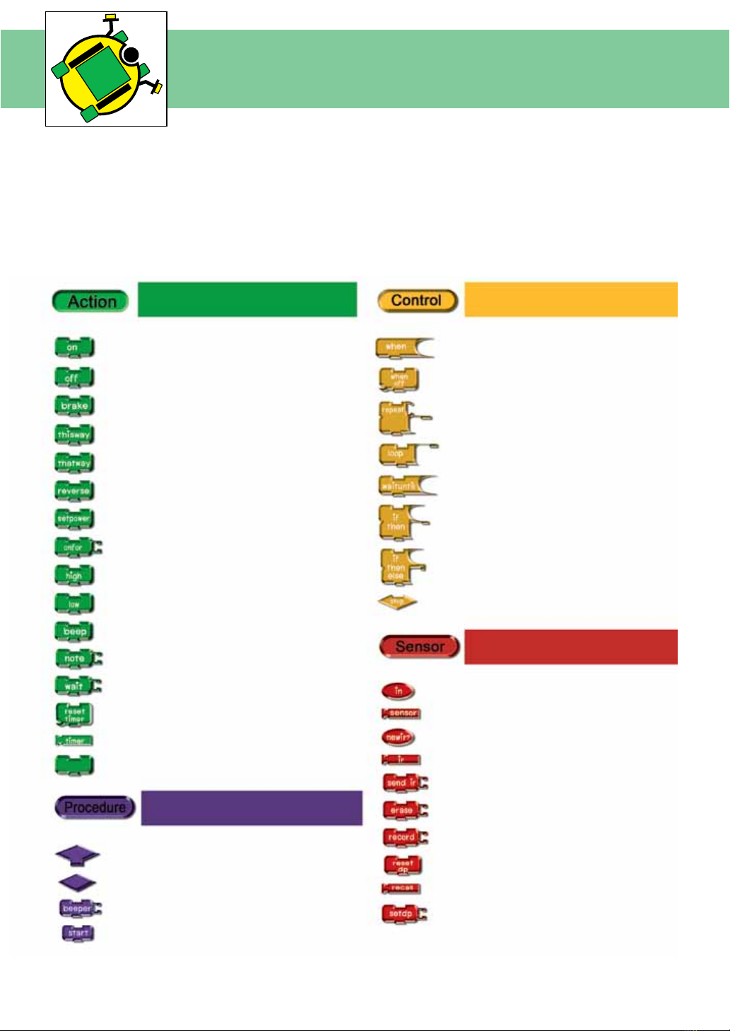
Command block
summary of LogoBlocks
LogoBlocks is a unique software that lets you create iconic programs to control the
i-BOX III controller. To create programs, you just drag blocks form the palette (on the
bottom left of the screen) and snap them together on the canvas (on the right side
of the screen). The buttons on the bottom left let you switch between palettes, each
containing a different set of commands.
Motor control, Sound
and Timer command
Condition and loops command
Procedure functions command
Sensor functions command
Drive motor Interrupt
Stop interrupt
Repeat loop
Loop operation
Wait condition
Check conditions
Check additional conditions
Stop program operation
Digital input block
Sensor block
Serial data checking
Serial data buffer
Serial data monitor
Delete data block
Record value to memory
Clear Data Pointer
Recall data from memory
Set data pointer
Stop motor
Brake motor
Forward direction
Backward direction
Reverse direction
Set power to motor
Set time of motor control
Send HIGH logic
Send LOW logic
Beep generation
Musical generation
Set delay time
Reset timer value
Read timer value
nop : No operation
Set of rules block
Procedure icon
Beep
Start sub procedure

9
Command block
summary of LogoBlocks
Number functions and arithmetic command
Declare variable
NOT : logical block operation
Adding
Subtraction
Multiplying
Divided
Modulus
Set number
Random numerical
Numerical comparison (Less than statement)
Numerical comparison (Equal statement)
Numerical comparison (More than statement)
AND : logical block operation
OR : logical block operation
XOR : logical block operation

10
ZX-LED : The LED output board
introduction
How it work ?
Interfacing with i-BOX III
The ZX-LED is digital output device module. The LED will lit when get the logic “1”
A light emitting diode (LED) emits light when current passes through it. The color of the LED usually just tells you what
color it will glow when current passes through it. The important markings on an LED are contained in its shape.
Since an LED is a one-way current valve, you have to make sure to connect it the right way, or it won’t work as intended.
LED has 2 terminals. One is called the anode, and the other is called the cathode. On the schematic symbol, the cath-
ode is the line across the point of the triangle and part drawing. For the part drawing, note that the LED’s leads are
different lengths. The longer lead is connected to the LED’s anode, and the shorter lead is connected to its cathode.
ZX-LED includes a transistor to drive current for supporting the low source current output port of microcontroller.
It ensures the LED on when the logic “1” applied to input.
ZX-LED is output device. Must connect with P0 and P1;
the digital output port of i-BOX III controller following the
gure on left. There is 4 command blocks for controlling
the ZX-LED
Set P0 as logic “1” (+5V)
Signal connector
Transistor current
amplier for driving LED
ZX-LED schematic diagram
8mm. LED
Set P1 as logic “1” (+5V)
Set P0 as logic “0” (0V)
Set P1 as logic “0” (0V)

11
Fun with LED
Connection diagram
Program development procedure with Cricket Logo
Dual LED blinking Cricket Logo example code
(LED.lgo)
(1) Connect i-BOX III controller to the computer.
(2) Open the Cricket Logo software.
(3) Type in LED.log listing into the Cricket Logo editor.
(4) Type in start on into the Run this box.
(5) Turn-on power of i-BOX III.
(6) Download the code into the i-BOX III by clicking on the DOWNLOAD button.
(7) Press RUN button on the i-BOX III controller. The RUN green LED is on and ZX-LED on P0 and P1 ports are blinked.
Computer has only USB port
Notebook computer
Desktop computer
CX-4 cable
CX-4 cable
USB interface
Serial (COM) port interface

12
Fun with LED
Program development procedure with LogoBlocks
(1) Connect i-BOX III controller to the computer.
(2) Open the LogoBlocks software.
(3) Drag and drop the command blocks as follows.
(3.1) Choose
Control group
(3.8) Select blocks.
(3.9) Copy the
selected blocks.
(3.10) Paste the
copied blocks.
(3.11) Change
some value.
The nish block codes are shown in the
LED.blk block code le.
(3.2) Drag
loop block
(3.3) Choose
Action group
(3.6) Drag wait block
to connect the latest
block code
(3.7) Double-click
to change value
to 50.
(3.4) Drag high
and low block
(3.5) Double-click
to change value
(4) Turn-on power of i-BOX III.
(5) Download the code into the i-BOX III by clicking on the
DOWNLOAD button. Wait for the downloading complete.
Observe the DOWNLOAD button released.
(6) Press RUN button on the i-BOX III controller. The RUN
green LED is on and ZX-LED on P0 and P1 ports are blinked.
Dual LED blinking LogoBlocks example code
(LED.blk)

13
Introduction to Switch /Touch sensor
Basic operation of Switch
Switch operation
The Touch / Switch Sensor module consist of 3 main components, the Wire input, LED Indication light
and the Switch. It will be give 2 status as Press and Release switch.
Switch/Touch sensor give 2 results as follows :
Result is logic “1” when switch is not pressed
or released. Condition is FALSE.
Result is logic “0” when switch is pressed.
Condition is TRUE.
Switch
LED indicator
Signal connector
Not press or release;
condition is FALSE.
Press; condition is TRUE.
Switch/Touch sensor
basic components
Switch/Touch sensor
schematic diagram
Release/Not press Press
14
Play with Switch sensor
The Touch / Switch Sensor module acts as a digital sensor. Connect the sensors to IN0 to IN3 respectively.
Testing
(1) Connect Switch sensor to IN3 o-BOX III controller
(2) Create the code Switch.lgo in Cricket Logo or
Switch.lbk in LogoBlocks
(3) Download the code to i-BOX III controller
(4) Press RUN switch. Press the Switch sensor and
observe the operation of Motor indicators. LED of motor
indicators are on when switch is pressed and off when
released.
Switch testing Cricket Logo example code
(Switch.lgo)
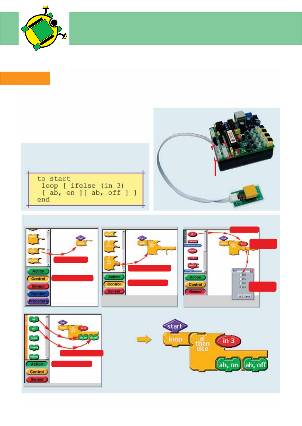
Switch testing LogoBlocks example code (Switch.lbk)
IN0 to IN3 connectors
(1) Choose Control group.
(2) Drag loop block.
(3) Drag if-then-else block.
(4) Choose Sensor group.
(8) Choose Action group.
(9) Drag on and off block.
(5) Drag in block.
(6) Double-click
on the in block.
(7) Change port
to in3.

15
Swith control LED activity
This example shows how to create the code to control LED at output port of i-BOX III controller. Switch
sensor at IN1 controls ZX-LED on P0 port. Other switch sensor is connected to IN3 of controller board and
controls ZX-LED at P0 port.
Switch controls LED Cricket Logo example code
(LEDSwitch.lgo)
Switch testing LogoBlocks example code
(LEDSwitch.lbk)
Code operation
p0 p1 are created
from global variable
This example code uses p0 and p1 variable for keeping the status of LED. If the switch at IN1 is pressed
and released, invert the current logic of P0 port from “1” to “0” or from “0” to “1” . Also switch at IN3
controls the logic at P1 port.

16
Building Robo-CIRCLE
Part list
i-BOX3.0 controller
2 of 120:1 DC motor
Gearboxes with mounting
Circle chasis
4 of 3x8mm.
at-head screws
2 of 2mm.
self-tapping screws
Box holder Wheels and Tires 2 of 33mm. metal spacer
Construction
(1) Attach 2 of DC motor gearboxes with the Box holder by 3x8mm. at-head screws at the position
following the picture below.
3x8mm.
at-head screws
3x8mm.
at-head screws

17
(2) Attach 2 of 33mm. metal spacers on the Box holder by 3x8mm. at-head screws at the position
following the picture below.
(3) Fix on the 2 wheels with rubber tires and attach them to the DCGearbox with the 2 of 2mm.
self-tapping screws provided in the kit.
Building Robo-CIRCLE
33mm. metal spacer
33mm. metal spacer
2mm. self-tapping screws

18
Building Robo-CIRCLE
(4) Attach the motor construction from step (3) with the Circle chasis at the position following the picture
below.
Tighten with 3x6mm. screws at 33mm. metal spacer position.
(5) Place i-BOX into the holder. Connect Motor A cable to the Blackconnector of ch-A and Motor B
to the white connector of ch-B.
* specic position of screw is hole of metal spacer
Your Robot is ready to GO!
Motor A is motor that is on Sensor connector side.
Motor B is motor that is on Motor connector side.
Screw position
Screw position
Motor A
Motor B

19
DC motor Gearbox operation
Robo-CIRCLE is moved by 2 of DC motor gearboxes. This topic explains about the DC motor gearbox
operation. Gears are used in tons of mechanical devices. They do several important jobs, but most
important, they provide a gear reduction in motorized equipment. This is key because, often, a small
motor spinning very fast can provide enough power for a device, but not enough torque. For instance,
an electric screwdriver has a very large gear reduction because it needs lots of torque to turn screws,
but the motor only produces a small amount of torque at a high speed. With a gear reduction, the
output speed can be reduced while the torque is increased.
Understanding the concept of the gear ratio is easy if you understand the concept of the
circumference of a circle. Keep in mind that the circumference of a circle is equal to the diameter
of the circle multiplied by Pi (Pi is equal to 3.14159...). Therefore, if you have a circle or a gear with a
diameter of 1 inch, the circumference of that circle is 3.14159 inches. Most gears that you see in real life
have teeth.
The rst driving gear of the gearbox system is a gear that attached with motor’s shaft. The next gear
is attached cause to change the speed and torque of system. It is called driven gear. If driven gear is
bigger than the driving gear; the torque increase but speed decrease. In the other hand, the driven
gear is smaller. The torque decrease and speed increase. The example simple gear system is shown in
the gure below. The rst gear is 9-teeth. Second gear is 36-teeth. The gearbox ratio of this system is 4:1
from the formula :
Teeth of the driven gear/Teeth of the driving gear
For the large gear ratio such as 64:1, we require more gears to make the system. Gears are often
connected together in gear trains.
The gure below shows the example of 64:1 ratio gear system.
Each part in the train is actually made in two parts, a small gear and a larger gear are connected to-
gether, one on top of the other. Gear trains often consist of multiple gears in the train. For this example
the gear ratio can calculate as follows :
Gear ratio of 3rd part x Gear ratio of 2nd part x Gear ratio of 1st part
36/9 x 36/9 x 36/9 = 64 : 1
Gear ratio
9-teeth driving gear
Driving gear (1) 9-teeth
Driven gear (1) 36-teeth
Driving gear (2) 9-teeth Driving gear (3) 9-teeth
Driven gear (2) 36-teeth Driven gear (3) 36-teeth
36-teeth driven gear

20
DC motor Gearbox operation
The Robo-CIRCLE gearbox ratio is 120:1. The inside gear system is shown in the picture below.
Robo-CIRCLE gearbox includes 5 of gears and 4 parts following the gure below. First driving gear is
8-teeth gear. The gear ratio of this system is :
Gear ratio part 4 x Gear ratio part 3 x Gear ratio part 2 x Gear ratio part 1
X X X
Driven gear (4) 28-teeth Driven gear (3) 36-teeth Driven gear (2) 36-teeth Driven gear (1) 36-teeth
= 118.59 : 1. It is 120:1 approximation.
Driving gear (4) 17-teeth Driving gear (3) 9-teeth Driving gear (2) 9-teeth Driving gear (1) 8-teeth
Calculation :
Driving gear (1) 8-teeth
Driven gear (1) 36-teeth Driven gear (3) 36-teeth
Driven gear (2) 36-teeth Driven gear (4) 28-teeth
Driving gear (3) 9-teeth
Driving gear (2) 9-teeth Driving gear (4) 17-teeth
This manual suits for next models
1
Table of contents
Popular Toy manuals by other brands

Fei Bao
Fei Bao Velox Assembly manual

KidKraft
KidKraft Step 'N Store 15602D Assembly instructions

Faller
Faller 2 WARNING GROSSES WITH FLASHING LIGHTS instructions

American Printing House
American Printing House Code & Go Robot Mouse Activity Set Activity guide

VTech Baby
VTech Baby Roar & Explore Wheel Parents' guide

SMART
SMART Table ST230i Removal Instructions

Mattel
Mattel Barbie T2694-0520 instructions

Faller
Faller 131242 manual

LeapFrog
LeapFrog Interactive Wooden Animal Puzzle instruction manual

Mega Construx
Mega Construx Kubros Halo Spartan Recon DXB91 Assembly instructions

Carson
Carson BIG Hughes 500 instruction manual

Fisher-Price
Fisher-Price GVY94 manual


