Infanor CYBELEC CybTouch 6 G-W User manual

CybTouch 6 G-W
Shears
Machine Parameters Manual v1.1

Page left blank intentionally

v1.1 16.01.12
PM_CybTouch6_ Shears_v1.1.doc page 3 of 42
TABLE OF CONTENTS
P01 MACHINE CONFIGURATION............................................................................................................6
Menu Button............................................................................................................................................6
Toggle Pages Button ..............................................................................................................................6
P01.01 Machine Type.............................................................................................................................7
P01.02 Start Pump Button......................................................................................................................7
P01.03 Automatic Cut.............................................................................................................................7
P01.04 Quantity ......................................................................................................................................7
P01.05 Material.......................................................................................................................................8
P01.06 Blade Gap...................................................................................................................................8
P01.07 Second Blade Gap .....................................................................................................................8
P01.08 Axis.............................................................................................................................................8
P02 MACHINE CONFIGURATION 2.........................................................................................................9
P02.01 Sheet Support.............................................................................................................................9
P02.02 Return to Sender (RTS)..............................................................................................................9
P03 MACHINE CONFIGURATION 3.........................................................................................................10
P03.01 Light............................................................................................................................................10
P03.02 Eco Mode ...................................................................................................................................10
P03.03 Store/Delete Programs in Level 0 ..............................................................................................10
P03.04 HMI Locked in Level 0................................................................................................................11
P03.05 Toggle Pages .............................................................................................................................11
P03.06 Show Cycle Steps ......................................................................................................................11
P03.07 Interfilling ....................................................................................................................................11
P03.08 Retraction ...................................................................................................................................12
P03.09 Analog Pressure.........................................................................................................................12
P03.10 Cutting Length Sensor................................................................................................................12
P04 MACHINE SETTINGS ........................................................................................................................13
Machine Settings Wizard........................................................................................................................13
P04.01 Max Programmable Cutting Length............................................................................................13
P04.02 Time Before Axis Start at BDC...................................................................................................13
P04.03 Default Time for Max Cutting Length..........................................................................................14
P04.04 Time to Close Hold-Downs.........................................................................................................14
P04.05 Time to Close Hold-Downs if not TDC max................................................................................14
P04.06 Timing Valves.............................................................................................................................14
P04.07 AutoCut Minimum Waiting Time at TDC ....................................................................................15
P04.08 Square Signal Low/High.............................................................................................................15
P05 PREFERENCES .................................................................................................................................16
P05.01 Axes Start at...............................................................................................................................16

v1.1 16.01.12
PM_CybTouch6_ Shears_v1.1.doc page 4 of 42
P05.02 Sheet Offset................................................................................................................................16
P05.03 Angle Control at TDC .................................................................................................................16
P06 AXIS SETTINGS -X-...........................................................................................................................17
P06.00 Display Resolution......................................................................................................................17
P06.01 Axis Type....................................................................................................................................17
P06.02 Closed Loop ...............................................................................................................................17
P06.03 Encoder resolution......................................................................................................................18
P06.04 Position Speed ...........................................................................................................................18
P06.05 Position Tolerance......................................................................................................................18
P06.06 One-Way Positioning..................................................................................................................18
Advanced button.....................................................................................................................................19
Axis Settings -X- Wizard.........................................................................................................................19
P06B ADVANCED AXIS REGULATOR X ................................................................................................21
P06b.01 Change Counting Direction ......................................................................................................21
P06b.02 Manual Speed ..........................................................................................................................21
P06b.03 Acceleration..............................................................................................................................21
P06b.04 Invert voltage & Speed at 10V..................................................................................................21
P06b.05 Closed Loop Frequency ...........................................................................................................21
P06b.06 Integrator factor........................................................................................................................21
P06b.07 Offset Voltage...........................................................................................................................22
P06b.08 Supervisor Error .......................................................................................................................22
P06b.09 Supervisor Speed Level ...........................................................................................................22
P06b.10 Control Time Out......................................................................................................................22
07 INDEXATION AXIS -X- .........................................................................................................................23
Indexation Axis -X- Wizard......................................................................................................................23
P07.01 Index Type..................................................................................................................................23
P07.02 Start Indexation in Reverse Logic ..............................................................................................24
P07.03 Start Indexation in Negative Direction........................................................................................24
P07.04 Indexation Speed........................................................................................................................24
P07.05 Index Position.............................................................................................................................24
P07.06 Minimum Limit ............................................................................................................................24
P07.07 Maximum Limit ...........................................................................................................................24
P07.10 Parking .......................................................................................................................................24
08 AXIS FUNCTIONS -X- ..........................................................................................................................25
P08.01 Blade Gap Factor .......................................................................................................................26
P08.02 Speed with input “Speed reduction” ...........................................................................................26
P09 DIGITAL INPUT CONFIGURATION ..................................................................................................27
P10 DIGITAL OUTPUT CONFIGURATION ..............................................................................................28
P11 ANALOG I/O CONFIGURATION .......................................................................................................29
P12 BLADE GAP.......................................................................................................................................30

v1.1 16.01.12
PM_CybTouch6_ Shears_v1.1.doc page 5 of 42
Blade Gap Wizard...................................................................................................................................31
P12.01 Inverted AD Input........................................................................................................................31
P12.02 Tolerance....................................................................................................................................31
P12.03 Advanced Stop ...........................................................................................................................31
P12.04 Overrun Distance........................................................................................................................31
P12.05 SP/SN Time................................................................................................................................31
P13 ANGLE AND CUTTING LENGTH......................................................................................................32
Angle and Cutting Length Wizard...........................................................................................................32
P14 ANGLE AND CUTTING LENGTH 2...................................................................................................33
P14.01 Inverted Input..............................................................................................................................33
P14.02 Resolution...................................................................................................................................33
P14.03 Minimum Limit ............................................................................................................................33
P 14.04 Distance Max TDC –Mechanical Stop......................................................................................33
P14.05 TDC Time Before Angle Control.................................................................................................33
P14.06 Cutting Angle Tolerance.............................................................................................................33
P14.07 Stop if Angle Sensor Max...........................................................................................................34
P14.08 Advanced stop, angle down/up ..................................................................................................34
P14.09 Advanced stop, cut down/up ......................................................................................................34
P15 PRESSURE ........................................................................................................................................35
Pressure Wizard .....................................................................................................................................35
P15.02 Minimum Pressure Beam Down.................................................................................................35
P15.03 Beam Up.....................................................................................................................................36
P15.04 Final Approach Up (min pressure) .............................................................................................36
P15.05 Ramp / Final Approach Up.........................................................................................................36
P15.06 Final Approach Speed Up ..........................................................................................................36
P15.07 Final Approach Gain...................................................................................................................36
P15.08 Cutting Angle..............................................................................................................................36
P15.09 Blade Gap...................................................................................................................................36
P15.10 Ramp cutting pressure ...............................................................................................................36
CHANGING ACCESS LEVEL SECURITY PASSWORDS:......................................................................37
Default passwords ..................................................................................................................................37
Changing passwords ..............................................................................................................................37
ERROR AND WARNING MESSAGES IN CYBTOUCH 6 FOR SHEARS................................................39
End User Messages................................................................................................................................39
Technician Messages .............................................................................................................................41

v1.1 16.01.12
PM_CybTouch6_ Shears_v1.1.doc page 6 of 42
P01 MACHINE CONFIGURATION
This manual explains the functionalities of the CybTouch 6 for shears,
independently of the limits imposed by the hardware and the subsequent
available inputs and outputs.
Menu Button
The Menu button allows you to exit the P01 Machine Configuration page or
to scroll through the other machine parameters pages:
Toggle Pages Button
The Toggle pages button is described in section P03.05 Toggle Pages.

v1.1 16.01.12
PM_CybTouch6_ Shears_v1.1.doc page 7 of 42
P01.01 Machine Type
Touch the Machine type field to choose the type of machine used with the NC.
Adjustable rake angle
Select this mode if your machine has a rake angle control to be managed by
the CybTouch NC. Selecting this option will give you access to dedicated
machine parameters for controlling this type of shears.
Swing
Select this mode if your machine has a fixed angle. The cutting length is
managed by a timer.
P01.02 Start Pump Button
Touch the Start Pump field to select:
No = Start Pump button is not available on screen.
Yes = Start Pump button is available on screen.
1 output (Pump_on) is dedicated to this.
Pump star delta button is available on screen.
3 outputs are dedicated to the star delta pump start.
1.0s = star duration
0.2s = star to delta commutation time
P01.03 Automatic Cut
The Automatic cut function can be enabled or not. This function is only available in
EasyCut mode. If it is enabled the icon will be available on screen.
If the Automatic cut input is configured, then this input must be active to enable
the icon selection on the screen. Usually, if this feature is configured a key switch
is wired on the machine to allow or not the Automatic cut functionality.
P01.04 Quantity
The Show quantity function can be enabled or not.
This function allows the operator to enter a number of times a program can be
repeated (number of pieces to be produced).
No: The quantity counter is not displayed.
Yes: The quantity counter is displayed; the operator can enter a
number of pieces to be produced.

v1.1 16.01.12
PM_CybTouch6_ Shears_v1.1.doc page 8 of 42
P01.05 Material
The Show material function can be enabled or not:
No: Material selection is not displayed.
Yes: Material selection is displayed; the operator can select the
material type.
P01.06 Blade Gap
The blade gap is adjusted depending on the selected material and thickness. These
values are set in the Material pages by the machine manufacturer. Usually the blade
gap is not be modified by the operator and is only shown to the operator.
No: No blade gap management; blade gap icon and value are not
displayed and cannot be configured in machine parameters.
Show only: Blade gap is calculated; icon and value are displayed
but cannot be configured in machine parameters (P12 Blade gap).
Electric or Hydraulic: choose the type of blade gap (electric
motor or hydraulic cylinder). The icon and value are displayed and
can be configured in machine parameters (P12 Blade gap).
Note: When Hydraulic is selected, a pressure output is required.
: Blade gap value is visible on working pages.
: Blade gap value is not visible on working pages.
Note: If operator needs to change the blade gap, it must be set as
visible and the programmable tolerances must be set in the Material
pages. See Materials section in user guide for more details
P01.07 Second Blade Gap
No: Only 1 blade gap actuator.
Yes: If a second blade gap is needed
Note: Blade gap feedback can only be potentiometer.
See P12 Blade gap page for calibration
P01.08 Axis
Backgauge: The back gauge is configured and can be used while
operating. It can be parked if necessary by the operator.
None: The back gauge isn’t used. This parameter setting is used
when the operator does not wish to use the back gauge or if the
back gauge is not setup on the machine.

v1.1 16.01.12
PM_CybTouch6_ Shears_v1.1.doc page 9 of 42
P02 MACHINE CONFIGURATION 2
P02.01 Sheet Support
The sheet support can be configured as follows:
No: No sheet support.
Sheet support 2 pos: Sheet support is set with 2 positions.
Sheet support 3 pos: Sheet support is set with 3 positions.
Disable support in zone: E.g. 0 –300 mm values are entered:
When cutting a part measuring up to 300 mm in length, the
sheet support cannot be used.
Note: Once configured, the corresponding outputs are available in the output list.
P02.02 Return to Sender (RTS)
The Return to Sender (RTS) function can be deactivated or configured as follows:
No: RTS is not configured.
Yes: RTS is configured and:
Retraction distance: Retraction distance for the back gauge
while in RTS mode. Usually in RTS mode the retraction distance is
greater than normal retraction.
Return speed: Speed at which the cut piece is pushed back to the
sender by the back gauge.
Min X dist: Minimum length of the part (or back gauge position) for
which the RTS function will be used. If the part measures less than
the value entered here, the RTS function will not be available. This
parameter also depends on the sheet support configuration (see
note below).
Max weight: Maximum weight of the part for using RTS function. If
the part is too heavy, the RTS function will not be activated. The
weight is calculated using specific weight on the Material page.
Note: If the sheet support is not configured, the RTS function cannot
be used. Therefore, if sheet support is on but disabled in zone
0-300 mm, RTS function cannot be used in zone 0–300 mm.

v1.1 16.01.12
PM_CybTouch6_ Shears_v1.1.doc page 10 of 42
P03 MACHINE CONFIGURATION 3
P03.01 Light
This light is usually used for the shadow line on the sheet metal. Once the light is
configured, one icon and one output are created.
P03.02 Eco Mode
The Eco mode parameter defines after how much time of operator or machine
inactivity the CybTouch will switch to economical mode.
When switching into Eco mode the Pump on output is turned off and the screen
becomes darker.
Current value is usually 5-15 min.
Setting the Eco Mode to 0.0 min deactivates Eco mode.
Note: If the Start Pump button is not configured on the screen, but
wired conventionally, the Eco mode off output can be used to
switch off the pump after the Eco mode time is reached. Please refer
to basic electrical diagrams.
P03.03 Store/Delete Programs in Level 0
Here you can choose whether or not operators with access level 0 can be authorized
to store or delete programs in the CybTouch.

v1.1 16.01.12
PM_CybTouch6_ Shears_v1.1.doc page 11 of 42
P03.04 HMI Locked in Level 0
The Human-Machine Interface can be locked in level 0. This is commonly used when
machines are left unattended on exhibitions to prevent visitors from changing
programs.
When set to Yes, the operator will need a code to access programming (level 2).
The HMI will be automatically locked every time:
The CybTouch is switched off.
After CybTouch switches to Eco mode.
The HMI can be locked manually when you open the menu and press
the padlock icon.
The unlocking code is “55".
(see section Changing Access Level Security Passwords for more details).
P03.05 Toggle Pages
If activated, the toggle button allows you to switch directly from any parameter
page "back" to the last working page visited before accessing the parameters.
Once you are in the working pages, touching allows you to return to the last
accessed parameter page.
This functionality is very useful for technicians during the machine set-up.
Its vivid orange color just informs the technician that this toggle page mode is active
and acts as a reminder to deactivate this functionality before machine delivery.
The Toggle pages button will disappear automatically from operator pages (Toggle
page parameter set to no) after 24 hours of inactivity.
P03.06 Show Cycle Steps
Cycle steps messages at the top of the screen can be displayed or not by activating or
deactivating the Show Cycle Steps parameter.
Ex: .
By default this parameter is set to Yes. The operator immediately knows in which
phase the machine currently is. This feature and the Machine Status pages are very
helpful during the first service calls between the operator and the service engineer.
P03.07 Interfilling
Not in function.
v1.1 16.01.12
PM_CybTouch6_ Shears_v1.1.doc page 12 of 42
P03.08 Retraction
Retraction of the back gauge can be set as follow:
No: The backgauge will not retract.
Yes always: The backgauge will always retract.
Yes selectable: The backgauge will retract or not, this is defined by operator.
The selection is only possible if AutoCut function is active.
Retraction distance: Backgauge retraction distance
Mandatory for thickness over: xx mm.
Retraction is mandatory if material is thicker
than this parameter value.
P03.09 Analog Pressure
Analog pressure can be configured if a proportional pressure valve is used for the
system pressure of the machine. Output manages ramps and pressure levels
depending on programmed material.
When P03.09 Analog Pressure is set to Yes, P15 Pressure becomes available
in machine parameters.
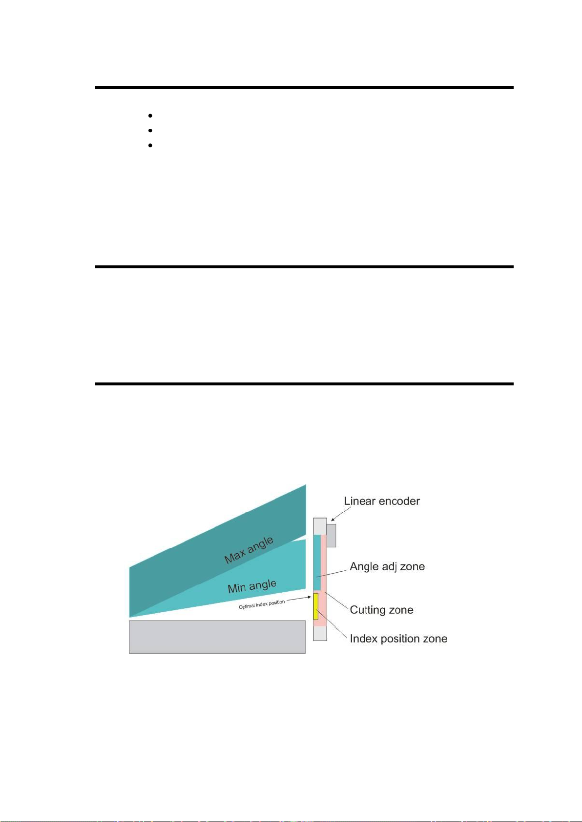
P03.10 Cutting Length Sensor
CybTouch 6 G allows the choice between a linear encoder or a potentiometer for
angle and cutting length functions.
If 2 blade gaps are used, the angle and cutting length sensor must be an encoder.
The sensor (potentiometer/linear encoder) must be positioned as far as possible to the
right of the machine in order to obtain maximum precision.
Encoder index must be positioned near to BDC, before the blades cross.
v1.1 16.01.12
PM_CybTouch6_ Shears_v1.1.doc page 13 of 42
P04 MACHINE SETTINGS
Machine Settings Wizard
When a swing shear machine is used, a Wizard is available by touching the
button. This allows you to measure the default time for the maximum cutting length.
See section P04.04 Default Time for Max Cutting Length for more details.
P04.01 Max Programmable Cutting Length
This parameter is only available with swing shear machines. It is the maximum cutting
length, depending on the machine dimensions.
P04.02 Time Before Axis Start at BDC
Time before the beam begins to move back up from BDC after making a cut.

v1.1 16.01.12
PM_CybTouch6_ Shears_v1.1.doc page 14 of 42
P04.03 Default Time for Max Cutting Length
This is the default time it takes to cut a piece with the previously set maximum cutting
length in P01 Maximum Cutting Length.
This is the value set by default when working in the EasyCut and Program page.
This parameter is only available with swing shear machines.
This time can easily be measured using the Wizard:
1. Touch the button, the below Wizard is displayed:
2. Press the foot pedal to lower the beam, the time it takes for the beam to go from
TDC position to BDC is measured (here 8.20 seconds).
3. Touch the button to exit the Wizard and return to the machine parameters
page.
4. The programmed cutting length value is now set.
P04.04 Time to Close Hold-Downs
The time it takes for the hold-downs to close can be set here in seconds. Once this
time is reached, the back gauge starts retraction.
P04.05 Time to Close Hold-Downs if not TDC max
The time it takes for the hold-downs to close when the beam hasn’t reached TDC
max.
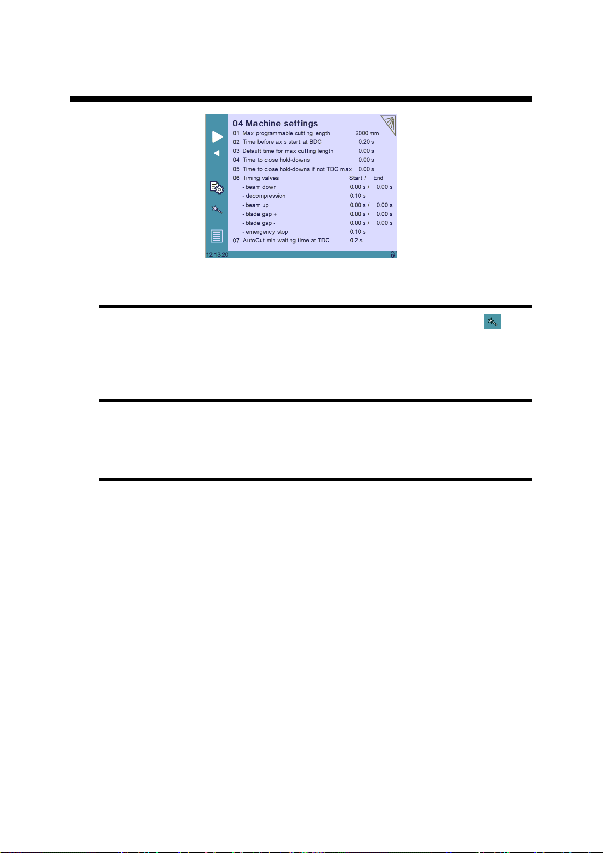
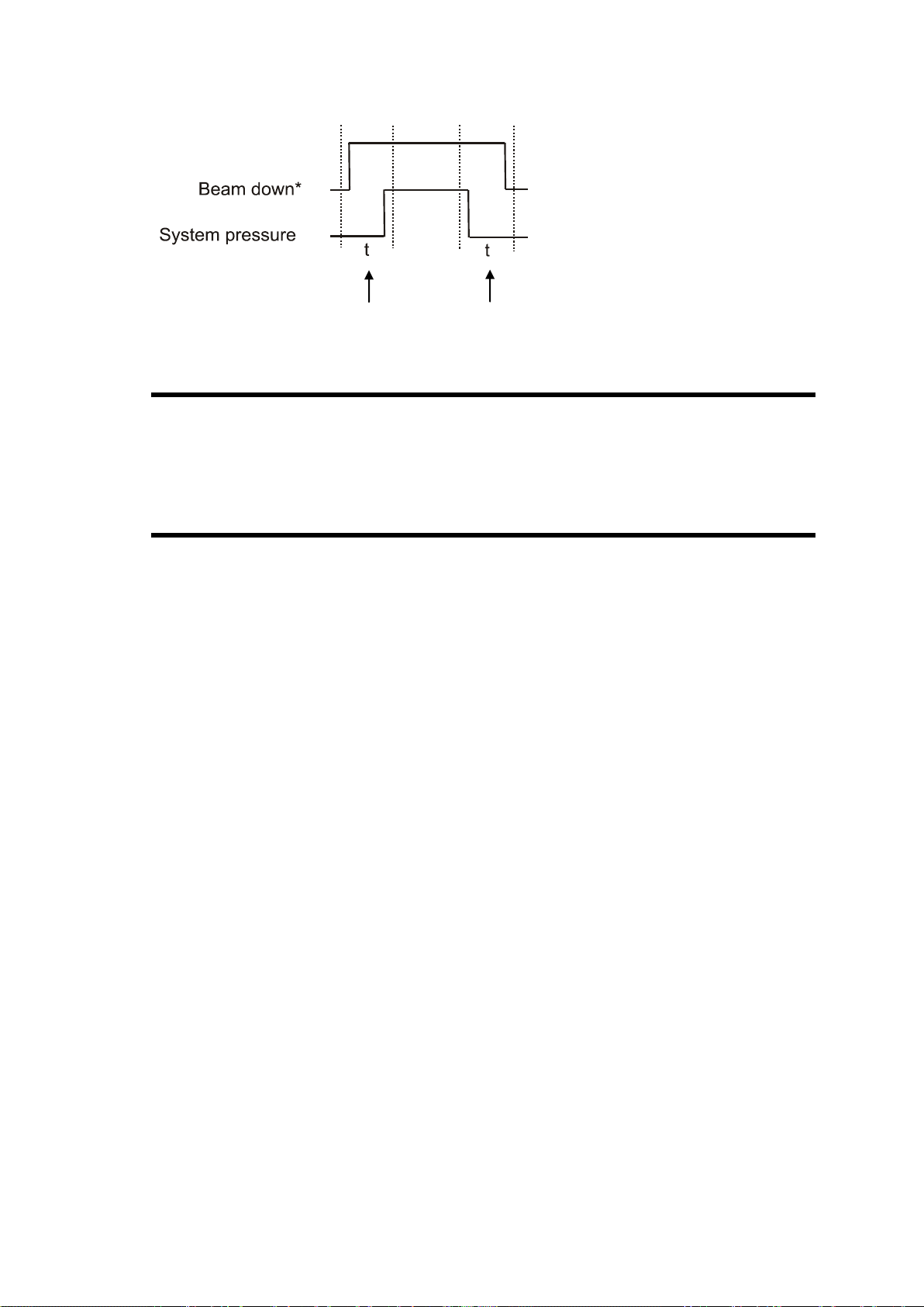
P04.06 Timing Valves
This parameter is used to manage system pressure for hydraulic systems in the
machine by timing the opening and closing of valves according to the system
pressure:
v1.1 16.01.12
PM_CybTouch6_ Shears_v1.1.doc page 15 of 42
E.g.: Beam down 0.20s / 0.30s
P04.07 AutoCut Minimum Waiting Time at TDC
This parameter determines the minimum time that the blade must stay at TDC
between cuts in automatic cut mode.
This is to ensure a smooth and less brutal change of direction/pressure in the system.
P04.08 Square Signal Low/High
The square signal is used to carry out tests on the machine. This signal is available on
one output Square signal and must be configured to be used.
*Or beam up, blade gap +, blade
gap -

v1.1 16.01.12
PM_CybTouch6_ Shears_v1.1.doc page 16 of 42
P05 PREFERENCES
P05.01 Axes Start at
The axes (back gauge) can be configured to start positioning at different moments,
depending on the position of the beam:
BDC if X SP:
oIf the axes movement will be in positive direction, axes (back
gauge) will start once the beam reaches BDC.
oIf the axes movement will be in negative direction, axes (back
gauge) will wait and start once the beam reaches TDC.
BDC: Back gauge starts moving when beam reaches BDC.
TDC: Back gauge starts moving when beam reaches TDC.
P05.02 Sheet Offset
Only available with adjustable rake angle machines.
If configured, allows the operator to set a series of cuts to be made in the center of the
machine without the beam having to return to TDC for each cut. This function is only
available if the machine is capable of stopping in the middle of a return of stroke.
P05.03 Angle Control at TDC
Only available with adjustable rake angle machines.
The CybTouch can be configured to check the blade angle at TDC.
It can be configured to perform this check every X number of cuts (value between 1
and 999 cuts). More frequent controls are usually used for older machines or
machines with hydraulic systems with minor leakage.
Setting this parameter to 0disables the angle check at TDC.

v1.1 16.01.12
PM_CybTouch6_ Shears_v1.1.doc page 17 of 42
P06 AXIS SETTINGS -X-
P06.00 Display Resolution
This value must be entered manually before using the Wizard.
Here you must set the displayed resolution for the selected axis to 0.01 mm,
0.1 mm or 1 mm.
P06.01 Axis Type
This value must be entered manually before using the Wizard.
Depending on the drive logic, you must select either:
For AC brushless motor, select Enable +/-10V.
For frequency converter with asynchronous motor , select either En/SN
0/10V, or SP/SN 0/10V:
P06.02 Closed Loop
Must be done manually before using the Wizard.
If you are using a frequency converter this parameter must be set to No.

v1.1 16.01.12
PM_CybTouch6_ Shears_v1.1.doc page 18 of 42
P06.03 Encoder resolution
The encoder resolution can be programmed if it is already known, but can also be
determined using the axis Wizard .
P06.04 Position Speed
Must be done manually before using the Wizard.
Here you must enter an approximate realistic positioning speed for the back gauge.
The real maximum positioning speed will then be determined by the Wizard.
P06.05 Position Tolerance
Must be done manually before using the Wizard.
Here you must enter the position tolerance accepted by the machine for the axis.
P06.06 One-Way Positioning
Back gauge positioning can be configured here. Various configurations are possible;
here are some examples which display how to configure this parameter:
Bi-directional positioning without final approach:
Bi-directional positioning with final approach of 5 mm at 1 mm/s:
One-way positioning with overrun of 30 mm:

v1.1 16.01.12
PM_CybTouch6_ Shears_v1.1.doc page 19 of 42
One-way positioning with overrun of 30 mm +final approach of 5 mm
and 1 mm/s:
Advanced button
Touching the Advanced button displays the P06b Advanced Axis Regulator
page.
These parameters are automatically generated by executing the Wizard described
below. See section P06b Advanced Axis Regulator X for more details.
Axis Settings -X- Wizard
Important: Before using the Wizard, a number of parameters must be set manually,
see section P06 Axis Settings –X-.
Touch the Wizard button to launch a Wizard to help you set the axis. Simply
follow the instructions in the Wizard for the following:
Axis movement direction:
Simply follow instructions in the Wizard.
Precede the same for the following steps.
Axis resolution
Axis position test
Axis limits
Axis identification:
1. Set the direction (01 Direction) in which the axis should move. The axis will
move for its identification for a certain time as defined in the next steps. Choose
the axis direction where the most distance is available for the stroke.
2. Set a test voltage (02 Voltage) for axis movement, 2 to 5 V preferably.
Start tests with a small v at the beginning in order to observe axis reaction.
3. Set the duration (03 Time) for axis movement, 2 to 4 sec preferably (but
depending on the axis speed). Start with small value.
4. Touch Start,
a. Axis starts a movement with above values, moves back and forth,
stops, and then returns near to the start position.
b. The Positioning OK message appears and the 10 speed at
10V value is calculated.
Note: P06.04 Positioning speed = 10 Speed at 10 V –15%.

v1.1 16.01.12
PM_CybTouch6_ Shears_v1.1.doc page 20 of 42
The P06.04 Positioning Speed can be made lower but never higher.
If an identification error [ ] occurs:
i. Err 1 = No motion detected. Should not happen if you
started the Wizard from the beginning.
ii. Err 2 = Not enough oscillations.
Increase the above identification time.
iii. Err 3= Oscillation amplitude.
Increase the above identification voltage.
iv. In all cases, make sure / verify that the amplifier / frequency
converter don't have internal ramps.
If ramps are set, turn them off (or program them to 0).
v. Make sure that no tests are performed by the drive at start
movement. If set so, turn these tests off.
5. Touch to move on to Axis Tuning.
Axis tuning:
1. Choose between closed loop and open loop. Keep open loop if frequency
converter is used.
2. Reduce the 04 Positioning speed if needed, never make it higher.
3. Increase or decrease manual speed depending on machine behavior.
4. Increase or decrease acceleration speed depending on machine behavior.
5. Enter a position in the field above and touch START.
6. Verify that X axis went to the right position. Repeat with different values.
Adjust 03 Acceleration to your convenience.
And if necessary set a final approach distance and or the one-way positioning
mode (in P06.06 One-way positioning).
All tests and axis adjustments can easily be made in this page.
After executing the Wizard, the backgauge is set to run in normal operating conditions.
Table of contents
Popular Medical Equipment manuals by other brands


Care Fusion
Care Fusion Snowden-Pencer Instructions for use

I-Tech
I-Tech MIO-CARE Tens user manual

Contec Medical Systems Co.
Contec Medical Systems Co. CONTEC08C manual

Ever Sharp Technology
Ever Sharp Technology ES2070 manual

B. Braun
B. Braun Aesculap Acculan 3Ti Instructions for use

Hillrom
Hillrom Yellofins Apex Instructions for use


