Infineon XENSIV CSK PAS CO2 User manual

Please read the Important Notice and Warnings at the end of this document
www.infineon.com page 1 of 54 2022-25-04
UM_2205_PL38_2205_101147
User Guide for XENSIV™ CSK PAS CO2
About this document
Scope and purpose
This document is a user guide for the XENSIV™ CSK PASCO2, provided as part of the connected sensor kit (CSK)
offering.
Intended audience
Customers interested in using CYSBSYSKIT-DEV-01 in combination with the XENSIV™ PAS CO2 or the XENSIV™
DPS368 barometric pressure sensor to build their own IoT solution for various consumer applications.

2 of 54
2022-25-04
User Guide for XENSIV™ KIT PAS CO2
Important notice
Table of contents
About this document....................................................................................................................... 1
Table of contents............................................................................................................................ 2
1Important notice.................................................................................................................... 4
2Introduction .......................................................................................................................... 5
2.1 Kit content ...............................................................................................................................................5
2.2 CYSBSYSKIT-DEV-01 ................................................................................................................................6
2.2.1 CYSBSYSKIT-DEV-01 main components............................................................................................6
2.3 XENSIV™ PAS CO2 wing ...........................................................................................................................7
2.3.1 XENSIV™ PAS CO2...............................................................................................................................7
2.3.2 XENSIV™ DPS368 barometric pressure sensor..................................................................................8
2.3.3 Board details ......................................................................................................................................9
2.3.4 Kit and system block diagram ...........................................................................................................9
2.4 Getting started.......................................................................................................................................10
2.5 Abbreviations ........................................................................................................................................11
3Quick IoT Experience .............................................................................................................12
4Build your own application.....................................................................................................21
4.1.1 XENSIV™ PAS CO2 sensor library .....................................................................................................21
4.1.2 XENSIV™ DPS3xx pressure sensor library........................................................................................21
4.2 Code examples ......................................................................................................................................21
4.2.1 Getting started with ModusToolbox™ .............................................................................................21
5Hardware description............................................................................................................24
5.1 CYSBSYSKIT-DEV-01 ..............................................................................................................................24
5.1.1 Baseboard components...................................................................................................................24
5.1.2 Hardware functional description ....................................................................................................28
5.1.3 CYSBSYS-RP01 module ....................................................................................................................28
5.1.4 PSoC™ 5LP........................................................................................................................................28
5.1.5 Serial interconnection between PSoC™ 5LP and module ..............................................................30
5.1.6 Power supply system .......................................................................................................................30
5.1.7 Expansion headers...........................................................................................................................32
5.1.8 QSPI ..................................................................................................................................................32
5.1.9 LED....................................................................................................................................................33
5.1.10 User button.......................................................................................................................................33
5.1.11 ECO ...................................................................................................................................................33
5.1.12 10-pin SWD/JTAG programming header.........................................................................................34
5.1.13 KitProg3: on-board programmer/debugger ...................................................................................34
5.1.14 Programming and debugging..........................................................................................................34
5.1.15 USB-UART bridge .............................................................................................................................34
5.1.16 USB-I2C bridge .................................................................................................................................35
5.2 XENSIV™ PAS CO2 wing .........................................................................................................................35
5.2.1 Wing board components..................................................................................................................35
5.2.2 Adafruit feather-compatible connectors ........................................................................................36
5.2.2.1 Power supply...............................................................................................................................38
5.2.3 Mechanical buttons..........................................................................................................................38
5.2.4 Hardware details..............................................................................................................................39
5.2.4.1 Wing board schematics...............................................................................................................39
Appendix A....................................................................................................................................45
Viewing debug data on the KitProg serial port of the kit .........................................................................................45

3 of 54
2022-25-04
User Guide for XENSIV™ KIT PAS CO2
Important notice
Reading LEDs .............................................................................................................................................................45
Troubleshooting guide ..............................................................................................................................................45
List of attributes with their definition and possible values......................................................................................48
Appendix A: Frequently asked questions.......................................................................................52
Revision history.............................................................................................................................53

4 of 54
2022-25-04
User Guide for XENSIV™ KIT PAS CO2
Important notice
1Important notice
Infineon Technologies AG (Infineon) provides the evaluation unit XENSIV™ KIT CSK PASCO2 which is built to
enable testing and evaluation of CYSBSYSKIT-DEV-01 in combination with the XENSIV™ PAS CO2 under the
following conditions:
•The evaluation unit is intended to be used for development, TESTING and EVALUATION PURPOSES
ONLY and is not considered by Infineon to be a finished end product fit for general consumer use.
•The evaluation unit (not being an end product) is not intended to be complete in various product
aspects such as required design, marketing, manufacturing, product safety, security and environmental
measures.
•The evaluation unit (evaluation kit) does not fall within the scope of the European Union directives and
FCC regulation, and therefore may not meet the technical requirements of these directives or other related
directives and regulations.
•The evaluation unit is provided for test and evaluation purposes only to evaluate XENSIV™ PAS CO2 or
XENSIV™ DPS368. The evaluation unit is provided “as is” without any warranty or liability of any kind.
•The user assumes all responsibility and liability for proper and safe handling of the goods including
following ESD precautions. Further, the user indemnifies Infineon from all claims arising from the handling or
use of the goods.
•NEITHER PARTY SHALL BE LIABLE TO THE OTHER PARTY FOR ANY DAMAGES INCLUDING (BUT NOT
LIMITED TO) INDIRECT, SPECIAL, INCIDENTAL AND CONSEQUENTIAL DAMAGES.
For additional information, please contact an Infineon application engineer or visit www.infineon.com.

5 of 54
2022-25-04
User Guide for XENSIV™ KIT PAS CO2
Introduction
2Introduction
The XENSIV™ KIT CSK PASCO2 supports customers in testing sensor-driven IoT products and CO2 use cases as
well as in prototyping. It offers a real-time sensor evaluation with custom configurations and cloud-based PAS
CO2 sensor data visualization.
2.1 Kit content
The XENSIV™ KIT CSK PASCO2 (Figure 1) comes with:
•Rapid IoT connect developer kit (CYSBSYSKIT-DEV-01) (Figure 2)
•XENSIV™ PAS CO2 wing (EVAL_PASCO2_Wing) (Figure 3)
Figure 1 XENSIV™ KIT CSK PASCO2
Figure 2 CYSBSYSKIT-DEV-01 rapid IoT connect developer kit
Figure 3 XENSIV™PAS CO2 wing

6 of 54
2022-25-04
User Guide for XENSIV™ KIT PAS CO2
Introduction
2.2 CYSBSYSKIT-DEV-01
The Rapid IoT connect developer kit carries a CYSBSYS-RP01 Rapid IoT connect system-on-module (SoM). The
Rapid IoT connect SoM includes a PSoC™ 6 MCU device, a CYW43012 single-chip radio, on-board crystals,
oscillators, chip antenna, and passive components. The PSoC™ 6 MCU device on the Rapid IoT connect SoM has
two cores: Cortex M0+ (CM0+) and Cortex M4 (M4). The firmware running on the PSoC™ 6 MCU can be split into
two parts: the application and device management. The device management part runs on the Cortex-M0+ core.
The applications part run on the Cortex-M4 core. The Cotex-M0+ core is called the network processor (NP). The
Cortex-M4 core is called the customer processor (CP). Resources such as flash, RAM and the peripherals are
divided between the NP and CP.
The Rapid IoT connect SoM is the easiest way to provide a secure, scalable, and reliable connection from your
device to your cloud. The Rapid IoT connect SoM is a pre-certified 802.11ac-friendly dual-band (2.4 and 5.0
GHz) Wi-Fi and Bluetooth® 5.0-compliant combo radio with an integrated PSoC™ 6 Secure IoT MCU provided in
an easy-to-use package. Included within the SoM are the crystals, oscillators, RF switches, passive components,
and antenna to help accelerate development of your secure IoT products. It provides up to 51 I/Os in a 26.6 x
14.0 x 2.5-mm castellated surface mount PCB for easy manufacturing.
Along with the Rapid IoT connect developer kit, Infineon® offers the Infineon® Rapid IoT connect cloud
platform. This Rapid IoT connect cloud platform allows users to quickly and easily connect their kits to the
cloud and see real time sensor data. Rapid IoT connect cloud platform provides several example projects that
can be easily programmed onto the user’s kit.
The user signs up with the Infineon® Rapid IoT connect cloud platform and registers the Rapid IoT connect
developer kit with the unique serial number printed on it. The user chooses an application for evaluation on the
Rapid IoT connect developer kit. The Rapid IoT connect cloud platform configures specific application images
which are available for download and programming on the Rapid IoT connect developer kit.
Rapid IoT connect cloud platform offers an array of services such as: Firmware over the air (FOTA) updates,
device management services such as Location services - parameter monitoring, and much more. Users who
desire to use these services for a large number of devices can connect with their respective Infineon® sales
support.
2.2.1 CYSBSYSKIT-DEV-01 main components
The Rapid IoT connect developer kit has the following features:
•CYSBSYS-RP01 module
•512-Mbit external Quad SPI NOR Flash that provides a fast, external expansion memory for data and code
•KitProg3 on-board SWD programmer/debugger, USB-UART, and USB-I2C bridge functionality. KitProg3 is
compatible with Mbed OS development flow and is CMSIS-DAP capable.
•A user LED, a user button, and a reset button
•Battery connector, charging IC, and charging indicator LED
•One KitProg3 mode button, one KitProg3 status LED, and one KitProg3 power LED
•Optiga Trust M advanced security controller for secure data storage
•Thermistor for sensing the ambient temperature.
•Power supply system consisting of a 3.6V buck-boost regulator with the 1.8V and 3.3V LDO derived from the
3.6V regulator. USB or LiPo battery powers the entire kit.

7 of 54
2022-25-04
User Guide for XENSIV™ KIT PAS CO2
Introduction
Figure 4 CYSBSYSKIT-DEV-01
2.3 XENSIV™ PAS CO2 wing
Increasingly efficient building insulation can help to mitigate the effects of climate change, but heavily insulated
buildings are not always good for human health. Poor ventilation can result in lower oxygen levels and a build-
up of carbon dioxide (CO2). Even moderate levels of CO2can have a negative impact on health and productivity.
Already at 1000 ppm, people begin to experience drowsiness and have difficulty concentrating. Consequently,
there is a growing demand for smart indoor air quality sensors that can “smell” rising levels of CO2and either
alert the user or trigger a system response. This user guide describes the required software and hardware,
including how to set up and get started with Infineon’s CO2sensor solution using the CSK. Please refer to the CSK
user manual for more details on the CSK. Additional documents are available and are listed at the end of this
document.
The board also compraises the XENSIV™ DPS368 digital barometric pressure sensor. This high-precision pressure
sensor can detect very small changes in barometric pressure, which makes it an ideal device for use cases where
accurate pressure event detection is required (e.g., opening of doors or windows, or fall detection).
Having both the CO2sensor and pressure sensor on the board gives the possibility to develop and test more
complex scenarios where data from both sensors is combined for more reliable event detection.
2.3.1 XENSIV™ PAS CO2
Infineon’s XENSIV™ PAS CO2 sensor leverages photoacoustic spectroscopy (PAS) technology to provide an
exceptionally small, real CO2sensor, overcoming the challenges of existing CO2sensor solutions. Its
unprecedentedly small form factor in a surface-mounted device (SMD) package allows for smooth high-volume
assembly and easy system integration.

8 of 54
2022-25-04
User Guide for XENSIV™ KIT PAS CO2
Introduction
The XENSIV™ PAS CO2 sensor integrates on the PCB the PAS transducer, including a detector, infrared source and
optical filter; a microcontroller for signal processing and algorithms; and a MOSFET chip to drive the infrared
source. The integrated microcontroller runs ppm calculations as well as advanced compensation and
configuration algorithms.
Key benefits
•Space savings in customers’ end products
•High-quality data and compliance with smart building standards
•Cost-effective high-volume assembly and easy system integration
•Plug and play for fast design-to-market
•Customer flexibility thanks to a variety of configuration options
Key features
•Exceptionally small form factor (14 x 13.8 x 7.5 mm3) sensor
•Accurate and robust performance at ppm level (±30 ppm ±3 percent of reading)
1
•Advanced compensation and self-calibration algorithms
•Configurable sampling rate via UART and I2C interfaces
2.3.2 XENSIV™ DPS368 barometric pressure sensor
The XENSIV™ DPS368 is a miniaturized digital barometric air pressure sensor robust against water, dust and
humidity. It offers high accuracy and low current consumption and is capable of measuring both pressure and
temperature. The pressure sensor element is based on a capacitive sensing principle which guarantees high
precision during temperature changes. The small package makes the XENSIV™ DPS368 ideal for mobile
applications and wearable devices. Due to its robustness, it can be used in harsh environments.
Key benefits
•Suitable even for harsh environments
•Easy to integrate and to operate; allows fast design-to-market
•High precision makes the XENSIV™ DPS368 an ideal device for applications such as fall detection, step
counting, door or window opening, and environmental scene monitoring in general
•Variety of configurations allows user to choose optimum sensor settings for target application
•In combination with the XENSIV™ PAS CO2, environmental pressure measured by the XENSIV™ DPS368
is used to increase CO2ppm accuracy of the XENSIV™ PAS CO2 sensor
Key features
•IPx8 certified: temporary immersion at 50 m for 1 hour
•Interface: I2C and SPI (both with optional interrupt)
1
Current engineering samples (early development samples) deviate from these specifications and are meant primarily to demonstrate
functionality.

9 of 54
2022-25-04
User Guide for XENSIV™ KIT PAS CO2
Introduction
•Operating modes: command (manual), background (automatic) and standby
•Pressure sensor precision: ± 0.002 hPa (or ±0.02 m) (high precision mode)
•Absolute accuracy: ± 1 hPa (or ±8 m)
•Package dimensions: 8-pin PG-VLGA-8-2, 2.0 mm x 2.5 mm x 1.1 mm
2.3.3 Board details
The CYSBSYSKIT-DEV-01 rapid IoT connect developer kit serves as the compute and connect part of the CSK.
Infineon sensor wing boards, such as the XENSIV™ PAS CO2 wing, sense the environment. The wing board has
Adafruit feather-compatible connectors to be stacked individually or combined with other CSK-compatible
wing boards on the rapid IoT connect developer kit.
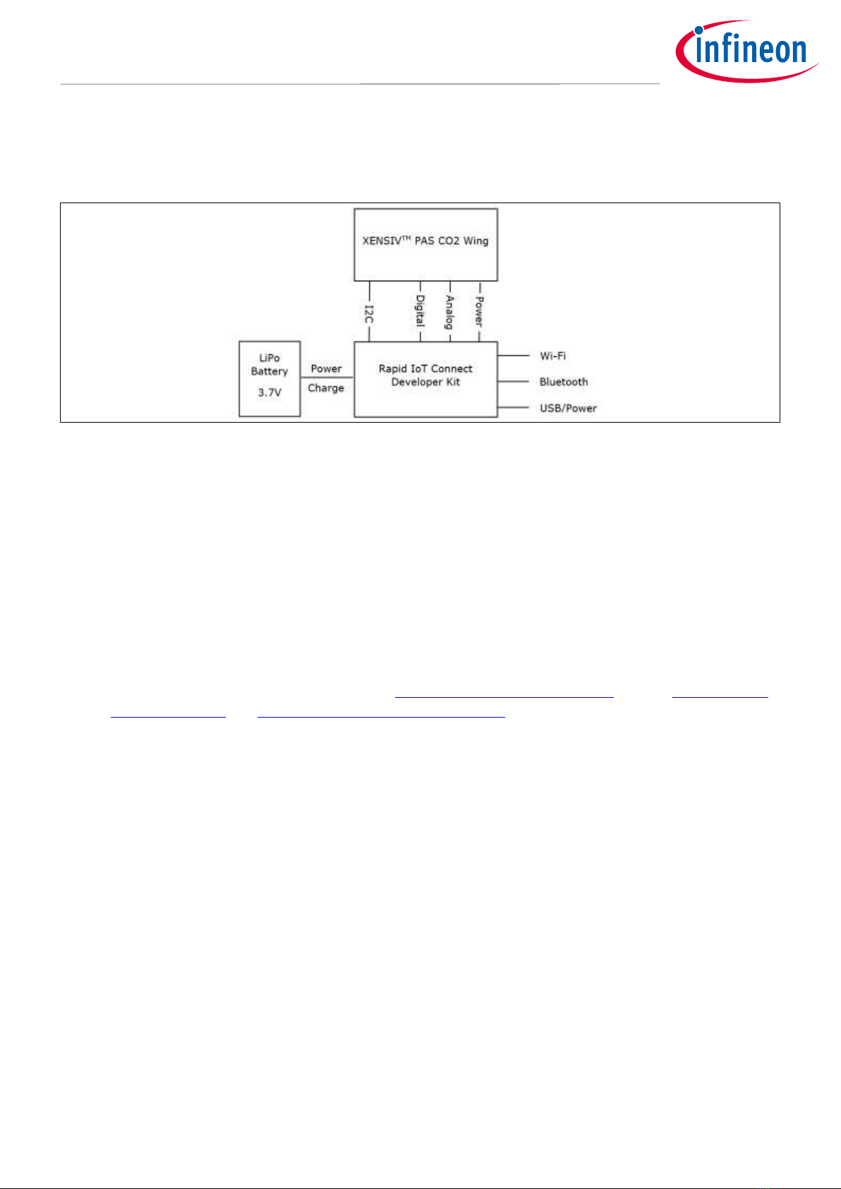
2.3.4 Kit and system block diagram
A block diagram of the wing board is shown in Figure 5. The wing board comprises the XENSIV™ PAS CO2, the
XENSIV™ DPS368 and the required power supply components. Power lines are highlighted in red. It is also
equipped with push buttons and LEDs.
Figure 5 XENSIV™ PAS CO2 wing block diagram
A system block diagram showing the shield connected to the CSK rapid IoT baseboard is depicted in Figure 4.
The interface from the shield to the rapid IoT baseboard includes I2C, digital signals, analog signals and power
28-pin
Adafruit
feather
connector
Two buttons:
user and reset
Step-up Converter U4
Switch U2
PAS CO2
SENSOR
3x LEDs
nRESET
USR_BUTTON
USB5V
VBAT
+3V
POWERDOWN
+3V_SWITCH
+12V
I2C SDA/SCL
+3V_SWITCH
INT
XENSIVTM
XENSIVTM
DPS368
U1
10 of 54
2022-25-04
User Guide for XENSIV™ KIT PAS CO2
Introduction
lines. The baseboard can interact with the outside world using Wi-Fi, Bluetooth, USB, or a combination of them
depending on the firmware/software (FW/SW) that is installed on the rapid IoT baseboard. The kit can be
powered from an external power supply or from a LiPo battery.
Figure 6 CSK system block diagram
2.4 Getting started
This guide will help you to get acquainted with the XENSIV™ KIT CSK PASCO2:
•Chapter Quick IoT Experience demonstrates how to read sensors and connect to the Rapid IoT connect
cloud platform in less the 10 minutes
•Chapter Build your own application explains how to use ModusToolbox™ to build your own application
to connect to your own cloud solution. ModusToolbox™ provides numerous code examples to make
this process easier.
Note: CYSBSYSKIT-DEV-01 requires ModusToolbox™ 2.2 or higher to design and debug applications.
Download and install ModusToolbox™ from www.cypress.com/modustoolbox. See the ModusToolbox™
Installation Guide and ModusToolbox™ IDE Quick Start Guide for additional information.
Users can experience the XENSIV™ KIT CSK PASCO2 in two ways:
a) Quick IoT experience for straightforward evaluation
b) Code examples in ModusToolbox™ for IoT solutions development

11 of 54
2022-25-04
User Guide for XENSIV™ KIT PAS CO2
Introduction
Figure 7 CSK experience steps
2.5 Abbreviations
Table 1 Abbreviation used in this document
Abbreviation
Description
BSP
Board support package
CO2
Carbon dioxide
CSK
Connected sensor kit
GPIO
General purpose input/output
HW
Hardware
I2C
Inter-integrated circuit
IoT
Internet of Things
LED
Light-emitting diode
PAS
Photoacoustic spectroscopy
PCB
Printed circuit board
PSoC
Programmable system-on-chip
SPI
Serial peripheral interface
UART
Universal asynchronous receiver transmitter
12 of 54
2022-25-04
User Guide for XENSIV™ KIT PAS CO2
Quick IoT Experience
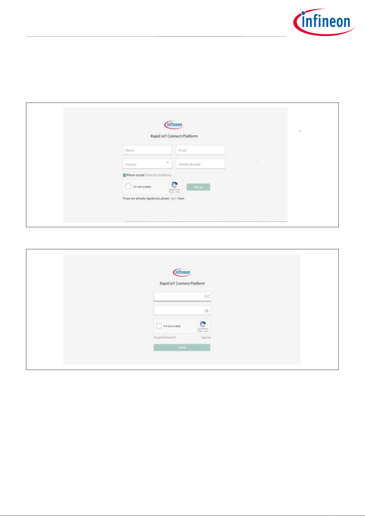
3Quick IoT Experience
1. Signup and login: Create an account with the Infineon® Rapid IoT connect cloud platform by signing up
with your email address. You will receive the password in your registered email address. You will be
prompted to change your password upon your first login to change it to the password of your choice.
Figure 8 Rapid IoT connect cloud platform sign-up view
Figure 9 Rapid IoT connect cloud platform login view
2. Add device: Click on the “Add device” button to add your new KIT CSK PASCO2. A pop-up wizard will guide
you through the process. Provide a name and enter the development kit serial number as shown in the
figure and click “Next” button to continue to next screen.

13 of 54
2022-25-04
User Guide for XENSIV™ KIT PAS CO2
Quick IoT Experience
Figure 10 Add device
Figure 11 Add device wizard
3. Application: Quick IoT experience will provide a complete IoT sensor experience, in 10 minutes or less, that
is inclusive of telemetry and fleet monitoring. After completing this wizard, you will download and program
your development kit with a pre-built hex file that prepares and configures the development kit with latest
Wi-Fi firmware, an example application, and all the required credentials to securely connect to the cloud.
Kindly note that example application will automatically use integrated temperature sensor. Please select
your desired application based on the XENSIV wing board present with you, in this case the XENSIV™ PAS
CO2 wing.

14 of 54
2022-25-04
User Guide for XENSIV™ KIT PAS CO2
Quick IoT Experience
Figure 12 Select application
4. Configure Wi-Fi network: You have the option to get the firmware to connect to your preferred WPA2
network by providing the Wi-Fi SSID and password or setup an access point/hotspot of WPA2-PSK security
with the following credentials.
SSID: IFX_Sensor
Security: WPA2-PSK
Password: S66M14022021
Figure 13 Configure and select network
5. Submit your device configurations: Please ensure all the details entered are correct before clicking on the
“Submit” button. You can go back to earlier screens by pressing “Previous” if you need to change anything.
Once you press “Submit”, a custom hex file is built for your device and a software bundle will be generated
to program your development kit.
Note: You can add/register a maximum of 5 devices with Rapid IoT connect cloud platform account.

15 of 54
2022-25-04
User Guide for XENSIV™ KIT PAS CO2
Quick IoT Experience
6. Download the zip package –Based on your laptop/PC’s operating system (Windows/Linux/Mac), you will
be given with a downloadable package containing the firmware image in a hex file and programming tool to
program your KIT CSK PASCO2. This will be a zip package. Click on the expand button to view the
detailed device status. Please click the download Button next to Success on the application for
downloading the zip package.
Figure 14 Device management dashboard
7. Program the KIT CSK PASCO2: Connect your development kit to your PC/laptop using a Micro USB cable.
Extract the zip and run the program_kit script (*.cmd file for Windows, *.sh for Linux and *.command for
Mac). For Linux and MAC users, please ensure that you run the script from a terminal with necessary
permissions. Please refer the README for detailed instructions.
Figure 15 Package contents

16 of 54
2022-25-04
User Guide for XENSIV™ KIT PAS CO2
Quick IoT Experience
8. Device management: Manage your device(s) and its configurations from the device management tab. Click
on the expand icon after the Created Date to view the respective device details.
Figure 16 Device connection status
Figure 17 Device attributes
9. Select desired application: Select Attributes tab on the device details. Click on the dropdown menu for
Sensor_Solution in the desired value. Please select the desired application based on the connected
Infineon® sensor wing board, in our case XENSIV PAS CO2. Your application will be set to “Thermistor” as

17 of 54
2022-25-04
User Guide for XENSIV™ KIT PAS CO2
Quick IoT Experience
default, since the only sensing element available on CYSBSYSKIT-DEV-01. After the application is selected,
the attributes will be pushed to the device and the device will reboot to the desired application.
Note: This may cause the connectivity to disconnect and reconnect from the Rapid IoT connect cloud platform.
Please refer Appendix for detailed list of attributes with their definition and possible values.
Figure 18 Select sensor solution
10.Change measurement period: Click on the Items per page drop-down menu at the bottom of the
Attributes tab and change the number of items accordingly so that you can view all attributes in one page.
You can change the pasco2_measurement_period value from 10 seconds up to 43200 seconds as needed.
You can also alter kit_mask_level to disable logs, enable minimal logs or full logs to cloud by changing the
drop-down menu.

18 of 54
2022-25-04
User Guide for XENSIV™ KIT PAS CO2
Quick IoT Experience
Figure 19 Kit_log level configuration

19 of 54
2022-25-04
User Guide for XENSIV™ KIT PAS CO2
Quick IoT Experience
Figure 20 Device log level configuration
View sensor data: Click on the desired tab on the top of the device details window to view your sensor data on
the cloud. Please select CO2 and Pressure if you have Infineon® XENSIV PAS CO2 wing board. Your application
will be set to “Thermistor” as default. Click on the “CO2” tab to view the data represented as a graph for easy
viewing. You can also download the raw data in csv format from the “Download” button on the top right corner.
By default, the data retention period is 14 days for a Standard User. In other worlds, data recorded more than
than 14 days ago cannot be retrieved. If you would like to have a data retention period greater than 14 days,
please get in contact with us for an upgraded account.

20 of 54
2022-25-04
User Guide for XENSIV™ KIT PAS CO2
Quick IoT Experience
Figure 21 PAS CO2 data visualisation
Table of contents
Other Infineon Network Hardware manuals


Popular Network Hardware manuals by other brands


Digital Equipment
Digital Equipment ChannelWorks Network Installer Guide

FiberHome
FiberHome AN5506-04 Series product manual

Aerotech
Aerotech Ensemble CL Hardware manual

weintek
weintek MT8070iER1 Series Installation instruction

Honeywell
Honeywell LonWorks protocol Installation and user manual

Cabletron Systems
Cabletron Systems ATX supplementary guide