Infineon BGT24LTR11 User manual

Application Note Please read the Important Notice and Warnings at the end of this document V1.0
www.infineon.com page 1 of 32 2021-03-31
AN615
24 GHz transceiver: BGT24LTR11
Distance2GoL (Software-Controlled FMCW) –XENSIV™ 24 GHz low-
power radar shield using BGT24LTR11 for range detection and human
tracking
B o a r d v e r s i o n V 3 . 0
About this document
Scope and purpose
This application note describes the key features of Infineon’s BGT24LTR11 Shield, part of Infineon’s 24 GHz
Distance2GoL radar system platform. The shield is the evaluation platform for the 24 GHz low-power
transceiver chip BGT24LTR11.
1. The application note describes the hardware configuration and specifications of the sensor module in
detail.
2. The document also provides a guide to configuring the hardware and implementing simple radar
applications with the firmware/software developed.
Intended audience
This document serves as a primer for users who want to get started with hardware design for range detection
and human tracking using a Software-Controlled FMCW radar technique at 24 GHz.
Related documents
Additional information can be found in the supplementary documentation provided with the Distance2GoL kit
in the Infineon Toolbox or from www.infineon.com/24GHz:
•Distance2GoL Software User Manual
•Radar Baseboard XMC4700 Application Note (AN602)

Application Note page 2 of 32 V1.0
2021-03-31
Distance2GoL (Software-Controlled FMCW) low-power radar shield using
BGT24LTR11 for range detection and human tracking
Table of contents
Table of contents
About this document....................................................................................................................... 1
Table of contents............................................................................................................................ 2
List of figures ................................................................................................................................. 3
List of tables .................................................................................................................................. 4
1Introduction .......................................................................................................................... 5
1.2 Key features.............................................................................................................................................6
1.3 Overview..................................................................................................................................................6
2Getting started ...................................................................................................................... 8
2.1 Additional materials..............................................................................................................................10
3System specifications ............................................................................................................11
4Hardware description: BGT24LTR11 Shield ..............................................................................12
4.1 Overview................................................................................................................................................12
4.2 Block diagram........................................................................................................................................13
4.3 Power supply.........................................................................................................................................15
4.4 EEPROM .................................................................................................................................................15
4.5 RF front end Shield................................................................................................................................15
4.6 BGT24LTR11 –24 GHz transceiver MMIC..............................................................................................16
4.7 Antennas................................................................................................................................................17
4.8 Analog baseband section......................................................................................................................18
4.8.1 IF section and FMCW ramp settings.................................................................................................20
5Power consumption analysis..................................................................................................21
6External pin header connectors ..............................................................................................22
7Measurement results.............................................................................................................25
7.1 Human range detection and tracking ..................................................................................................25
7.2 Temperature check for out-of-band emissions ...................................................................................26
8Frequency band and regulations.............................................................................................28
8.1 24 GHz regulations ................................................................................................................................28
8.2 Regulations in Europe...........................................................................................................................28
8.3 Regulations in the United States of America........................................................................................28
9Authors................................................................................................................................29
10 References ...........................................................................................................................30
Revision history.............................................................................................................................31

Application Note page 3 of 32 V1.0
2021-03-31
Distance2GoL (Software-Controlled FMCW) low-power radar shield using
BGT24LTR11 for range detection and human tracking
List of figures
List of figures
Figure 1 Distance2GoL demo platform ............................................................................................................7
Figure 2 Steps 1 to 3 to get started with the Distance2GoL demo board........................................................8
Figure 3 Steps 4 to 6 to get started with the Distance2GoL demo board........................................................9
Figure 4 Steps 7 to 9 to get started with the Distance2GoL demo board......................................................10
Figure 5 BGT24LTR11 Shield board with main components and dimensions..............................................12
Figure 6 Block diagram –Distance2GoL.........................................................................................................14
Figure 7 Block diagram –power supply concept ...........................................................................................15
Figure 8 EEPROM block diagram.....................................................................................................................15
Figure 9 RF front-end overview (top)..............................................................................................................16
Figure 10 Block diagram –BGT24LTR11 MMIC.................................................................................................16
Figure 11 Simulated radiation pattern for array antennas..............................................................................17
Figure 12 Baseband amplifier chain –block diagram......................................................................................18
Figure 13 Baseband amplifier chain –schematic.............................................................................................18
Figure 14 Baseband frequency response for low-gain and high-gain stages .................................................19
Figure 15 External headers –P1, P2, P3, P4, P5 and P6 ...................................................................................22
Figure 16 Human target detection range with respect to detection area ......................................................25
Figure 17 Bandwidth check at 25° inside temperature chamber ....................................................................26
Figure 18 Bandwidth check at +85° inside temperarture chamber.................................................................26
Figure 19 Bandwidth check at -40° inside temperature chamber...................................................................27

Application Note page 4 of 32 V1.0
2021-03-31
Distance2GoL (Software-Controlled FMCW) low-power radar shield using
BGT24LTR11 for range detection and human tracking
List of tables
List of tables
Table 1 Distance2GoL (Software-Controlled FMCW) module performance specifications.........................11
Table 2 Baseband amplifier to MCU pin connections...................................................................................19
Table 3 Baseband amplifier components and settings................................................................................19
Table 4 IF vs. FMCW ramp parameters vs. target distance ...........................................................................20
Table 5 Power consumption overview..........................................................................................................21
Table 6 Power consumption calculation.......................................................................................................21
Table 7 External headers (P1) –pin description............................................................................................22
Table 8 External headers (P2) –pin description............................................................................................23
Table 9 External headers (P3) –pin description............................................................................................23
Table 10 External headers (P4) –pin description............................................................................................23
Table 11 External headers (P5) –pin description............................................................................................23
Table 12 External headers (P6) –pin description............................................................................................24

Application Note page 5 of 32 V1.0
2021-03-31
Distance2GoL (Software-Controlled FMCW) low-power radar shield using
BGT24LTR11 for range detection and human tracking
Introduction
1Introduction
The Distance2GoL radar system is a demo platform for Infineon’s 24 GHz silicon-germanium (SiGe) BGT24LTR11
radar chipset. It consists of two boards –the microcontroller board: Radar Baseboard XMC4700, and a radar
front-end board: BGT24LTR11 Shield. This document focuses on the BGT24LTR11 Shield assembled for a
software-controlled Frequency Modulated Continuous Wave (FMCW) implementation. Detailed information
about the Radar Baseboard XMC4700 can be found in the corresponding application note (AN602).
The system is designed to enable customers to carry out prototyping and system integrations as well as initial
product feature evaluations. The platform is a low-power solution for tracking human presence and detecting
range. These features of the board make it suitable for various applications such as presence sensing, proximity
sensing and motion detection. These use cases target applications such as outdoor security cameras, smart-
home devices and lighting control.
The main radar technique used on the platform is FMCW for range estimation. In FMCW, the time delay between
the transmitted and received chirp is used for measuring the distance to the target(s). The transmitted and
received signals are mixed and then quantized for further processing. A Software-Controlled loop performs the
frequency control and ramp generation. This eliminates the need for a high-cost PLL IC, hence reducing system
cost. The circuitry is designed for low power consumption. Two-stage low-noise baseband amplification stages
are used for enhanced target detection. The baseband section is configurable for different cut-off frequencies
and gain requirements of different applications. The module also offers the possibility of using a battery for
operation.
The module provides a complete radar system evaluation platform, including demonstration software and a
basic graphical user interface (GUI), which can be used to display and analyze acquired data in time and
frequency domains. An onboard debugger with licensed firmware from SEGGER enables easy debugging over
USB. Infineon’s powerful, free-of-charge toolchain DAVE™ can be used for programming the XMC4700
microcontroller. The system also features integrated micro-strip patch antennas on the PCB with design data,
thereby eliminating antenna design complexity at the user end.
This application note describes the key features and hardware configuration of the BGT24LTR11 Shield in
detail.

Application Note page 6 of 32 V1.0
2021-03-31
Distance2GoL (Software-Controlled FMCW) low-power radar shield using
BGT24LTR11 for range detection and human tracking
Introduction
1.2 Key features
The primary features of the Distance2GoL radar system are as follows:
•Detects distance of a human in a user-configurable range (1 to 15 m)
•Detects distance and velocity of the closest human or moving target
•Low power consumption
•Two-board topology for RF section and microcontroller sections
•Two customizable analog amplifier stages for the RX channel
•Micro-strip patch antennas with 10 dBi gain and 29 x 80 degree Field of View (FoV)
•Multiple power supply possibilities –micro-USB, external power supply or LiPo battery
•Compatible with Arduino for ease of use and prototyping
•Operates in different weather conditions, including rain, fog, etc.
•Can be hidden in the end application as it detects through non-metallic materials
Note:The platform serves as a demonstrator platform with the software to perform simple motion sensing. The
test data in this document show typical performance of Infineon-produced platforms. However, board
performance may vary depending on the PCB manufacturer and specific design rules imposed and
components used.
1.3 Overview
The platform is a stack-up of two boards –BGT24LTR11 Shield (radar front end) and radar baseboard XMC4700
(for signal processing).
The Distance2GoL radar system consists of the following key components:
•BGT24LTR11 –highly integrated 24 GHz transceiver IC with one transmitter (TX) and one receiver (RX)
•XMC4700 –32-bit ARM® Cortex®-M4 based microcontroller for signal processing
•IRLHS2242 –20 V single P-channelMOSFETs for duty-cycle operation
•MCP73831T –battery manager for charging and using the battery
•CW1280T –EEPROM to store board identifier information
•MOLEX 047571001 –SD card reader for storing raw data
•XMC4200 –32-bit ARM® Cortex®-M4 based microcontroller for debugging

Application Note page 7 of 32 V1.0
2021-03-31
Distance2GoL (Software-Controlled FMCW) low-power radar shield using
BGT24LTR11 for range detection and human tracking
Introduction
Distance2GoL
Radar
Baseboard
XMC4700
BGT24LTR11
Shield Distance2GoL
Figure 1 Distance2GoL demo platform
Note: The BGT24LTR11 Shield in Distance2GoL platform is assembled for Software-Controlled FMCW
operation.
The circuitry for the BGT24LTR11 Shield (Software-Controlled FMCW) is designed to perform human target
range detection and tracking with low power consumption. In this approach, the BGT24LTR11 MMIC is
controlled using a software-based open-loop concept. Frequency is measured periodically and VCO is tuned
accordingly. This implementation has the advantage of reducing the PCB space, BOM cost and power
consumption by eliminating the external (Phase Locked Loop) PLL IC. System performance might be lower than
an external PLL, but can address a lot of applications like smart lighting, motion sensing or proximity detection,
etc.
Application Note page 8 of 32 V1.0
2021-03-31
Distance2GoL (Software-Controlled FMCW) low-power radar shield using
BGT24LTR11 for range detection and human tracking
Getting started
2Getting started
This section provides a quick step-by-step process to get started with the Distance2GoL board. Some of the
steps are optional, for going deeper into the analysis of the board, the firmware and the extracted signals.
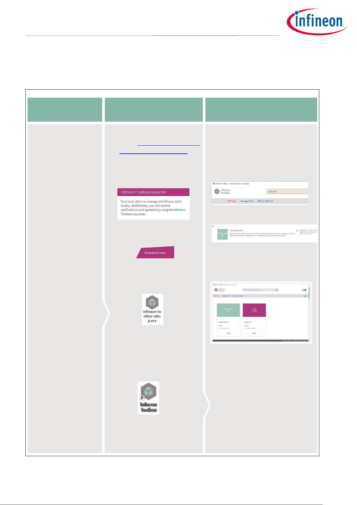
STEP 1
STEP 2
STEP 3
Box contents
•BGT24LTR11 Shield
(Software-
Controlled FMCW)
•Radar Baseboard
XMC4700
Infineon Toolbox
•Go to: Infineon Products and
Tools - Infineon Toolbox
•Click on “Infineon Toolbox
Launcher” link.
•Scroll down and click on the
“Download now”button.
•Run the “infineon-toolbox-
setup.exe” file.
•“Accept” the
license agreement.
•Finish installation. Create a
desktop shortcut.
Install Distance2GoL kit
•Open “Infineon Toolbox”.
•Click on the “Manage tools” tab.
•Search for “Distance2GoL Kit”.
•Click on “Install”.
•“Accept” the license agreement.
•Finish installation.
Figure 2 Steps 1 to 3 to get started with the Distance2GoL demo board

Application Note page 9 of 32 V1.0
2021-03-31
Distance2GoL (Software-Controlled FMCW) low-power radar shield using
BGT24LTR11 for range detection and human tracking
Getting started
STEP 4
STEP 5
STEP 6
Download SW/HW package
•Open “Infineon Toolbox”.
•Click on “Distance2GoL Kit”.
•Follow the instructions
mentioned on the left tab
“Getting Started”.
•Save the setup file and run it.
•Browse to the preferred
location to store the files.
Connect board
•Insert the micro-USB
cable into the Radar
Baseboard XMC4700
“Debug”port.
•Insert the USB connector
into the PC’s USB port.
If the device driver is not
recognized:
Right-click on “My Computer”
Manage Device Manager
Other devices Right-click
on “Unknown device”
Update Driver Software
Browse
Firmware_Software
XMC_Serial_Driver.
Firmware update
•Download and install
SEGGER J-Link USB driver for
Windows:
•Connect board as STEP 5
•Open Infineon Toolbox
Radar GUI Device Flash
Firmware.
•Select Device “Distance2GoL /
Sense2GoL Pulse” and select
“D2GL_SC_FMCW.hex”.
Firmware
•Click on “Flash Firmware”.
Figure 3 Steps 4 to 6 to get started with the Distance2GoL demo board
www.segger.com/download
s/jlink/#J-
LinkSoftwareAndDocument
ationPack
Optional
D2GL-HW-SW.exe
Optional

Application Note page 10 of 32 V1.0
2021-03-31
Distance2GoL (Software-Controlled FMCW) low-power radar shield using
BGT24LTR11 for range detection and human tracking
Getting started
STEP 7
STEP 8
STEP 9
View and edit source code
•Download and install the
DAVE™IDE tool:
•Go to Firmware_Software
DAVE project. Unzip the
DAVE™project files of your
choice.
•Run DAVE™ IDE.
•Import DAVE™ projects and
debug.
Radar GUI
•Disconnect micro-USB cable
from “Debug” port and
connect it to “Default” port.
•Open Radar GUI.
•Real-time data is now on
your screen.
MATLAB interface
•Go to: Firmware_Software
Communication Library
ComLib_Matlab_Interface
Examples GettingStarted.
Copy the path.
•Open MATLAB. Paste the path
in the top tab.
“extract_raw_data.m”file will
show up on the left tab.
•Connect board as STEP 8.
•Click on “Run”to see raw data.
Figure 4 Steps 7 to 9 to get started with the Distance2GoL demo board
2.1 Additional materials
The board comes with an additional downloadable package for customer support. This can be downloaded
through Step 4 in Figure 3. The package includes:
•Application Notes
•Software User Manual
•Altium PCB project
•Schematics
•Bill of Materials (BOM)
•Production data
•DAVE™ project and FW binary files
•Radar GUI XML settings files
•3D model files
•Power consumption calculator
https://infineoncommun
ity.com/dave-
download_ID645
Optional
Optional
Application Note page 11 of 32 V1.0
2021-03-31
Distance2GoL (Software-Controlled FMCW) low-power radar shield using
BGT24LTR11 for range detection and human tracking
System specifications
3System specifications
Table 1 gives the specifications of the Distance2GoL (Software-Controlled FMCW) radar system.
Table 1 Distance2GoL (Software-Controlled FMCW) module performance specifications
Parameter
Unit
Min.
Typ.
Max.
Comments
System performance
Speed
km/h
0
-
10
Distance
m
1
15
25
Human target
Power supply
Supply voltage
V
3.3
5
5.5
Supplied via the Baseboard
Supply current
mA
50
All blocks on (only the Shield)
Transmitter characteristics
Transmitter frequency
GHz
24.025
24.125
24.225
Effective isotropic radiated power
(EIRP)
dBm
+14
Conditions:
BGT POUT: +6 dBm
Loss (TXOUT to ant. input = 2
dB)
Simulated ant. gain = +10 dBi
Receiver characteristics
Receiver frequency
GHz
24.025
24.125
24.225
IF conversion gain –
(stage 1)
dB
30
Customizable by re-soldering
baseband section (Table 3)
IF conversion gain –
(stage 1 + stage 2)
dB
57
Customizable by re-soldering
baseband section (Table 3)
-3 dB bandwidth –
(stage 1 + stage 2)
kHz
7
15
Customizable by re-soldering
baseband section (Table 3)
Antenna characteristics (simulated)
Antenna type
1 x 4
Horizontal –3 dB beamwidth
Degrees
80
Elevation –3 dB beamwidth
Degrees
29
Horizontal sidelobe level
suppression
dB
13
Vertical sidelobe level suppression
dB
13
Note: The above specifications are indicative values based on typical datasheet parameters of
BGT24LTR11 and simulation of several other parameters (antenna characteristics and baseband
section) and can vary from module to module. The numbers above are not guaranteed indicators
for module performance for all operating conditions.

Application Note page 12 of 32 V1.0
2021-03-31
Distance2GoL (Software-Controlled FMCW) low-power radar shield using
BGT24LTR11 for range detection and human tracking
Hardware description: BGT24LTR11 Shield
4Hardware description: BGT24LTR11 Shield
This section presents a detailed overview of the BGT24LTR11 Shield hardware specifications, including the MMIC
considerations, power supply and board interfaces.
4.1 Overview
The radar Shield is shown in Figure 5. It contains the following sections:
•RF part –consists of the Infineon 24 GHz radar MMIC –BGT24LTR11 and includes micro-strip patch
antennas for the TX and RX sections
•Analog amplifier part –amplifies the in-phase and quadrature-phase signals from the MMIC for the
digital part
•EEPROM part –to store data such as board identifier information
BGT24LTR11
MMIC
PMOS switch
Operational amplifiers
(base band section)
Connectors
to Radar
Baseboard
External pin
headers
LDO
Voltage level
translator
66 mm
Arduino-compatible
connectors
Arduino-compatible
connectors
EEPROM
Metal
shielding
TX and RX
antennas
Figure 5 BGT24LTR11 Shield with main components and dimensions

Application Note page 13 of 32 V1.0
2021-03-31
Distance2GoL (Software-Controlled FMCW) low-power radar shield using
BGT24LTR11 for range detection and human tracking
Hardware description: BGT24LTR11 Shield
The Shield demonstrates the features of the BGT24LTR11 RF front-end chip and gives the user a customizable
radar solution. The board enables implementation of different baseband settings, VCO control, etc. to get
closer to a custom-fit solution for the use case. It also makes it possible to quickly gather sampled radar data
that can be used to develop radar signal processing algorithms on a PC or implement target detection
algorithms directly on the microcontroller using DAVE™.
4.2 Block diagram
Figure 6 shows the block diagram of the Distance2GoL system. It consists of the highly integrated 24 GHz
transceiver IC BGT24LTR11 with 1 TX and 1 RX antenna. The hardware consists of two main parts: one Software-
Controlled FMCW BGT24LTR11 Shield and one microcontroller unit with XMC4700.
In order to keep the output frequency within the industrial, scientific and medical (ISM) band and generate the
frequency ramp, the tuning voltage (V_TUNE) is software-controlled via a Digital-to-Analog Converter (DAC) in
the microcontroller unit. The DAC output (V_TUNE_IN) is smoothed by two RC low-pass filters and fed to the
V_TUNE input of the BGT24LTR11. The IF outputs (I/Q signals) are first bandpass filtered by two stages of op-
amps and then sampled by four synchronized Analog-to-Digital Converters (ADCs), which are built into the
XMC4700 MCU. The user can select the output of the first amplification stage (low-gain output) for sampling for
low-range applications. The op-amps are also duty-cycled for a low power consumption using control signals
(BB1_EN and BB2_EN).
An initial RF within the ISM band at the start-up of the radar system is ensured by utilizing the built-in voltage
source V_PTAT (Proportional-to-Absolute Temperature). After enabling VCC_PTAT, the output voltage is
sampled by an ADC and set by the DAC as V_TUNE. The Capture-and-Compare Unit (CCU) of the XMC4700
measures the divider output (DIV_OUT) of the BGT24LTR11 MMIC to supervise the current RF and (re)calibrate
the start and stop frequencies if required. During this process, VCC_PTAT is also enabled to set the correct
divider frequency.
For optimizing the power consumption of the system, the BGT24LTR11 MMIC is duty cycled, along with the
building blocks of divider and PTAT using control signals from the MCU (VCC_BGT_EN, VCC_DIV_EN and
VCC_PTAT_OUT).

Application Note page 14 of 32 V1.0
2021-03-31
Distance2GoL (Software-Controlled FMCW) low-power radar shield using
BGT24LTR11 for range detection and human tracking
Hardware description: BGT24LTR11 Shield
Figure 6 Block diagram –Distance2GoL
Application Note page 15 of 32 V1.0
2021-03-31
Distance2GoL (Software-Controlled FMCW) low-power radar shield using
BGT24LTR11 for range detection and human tracking
Hardware description: BGT24LTR11 Shield
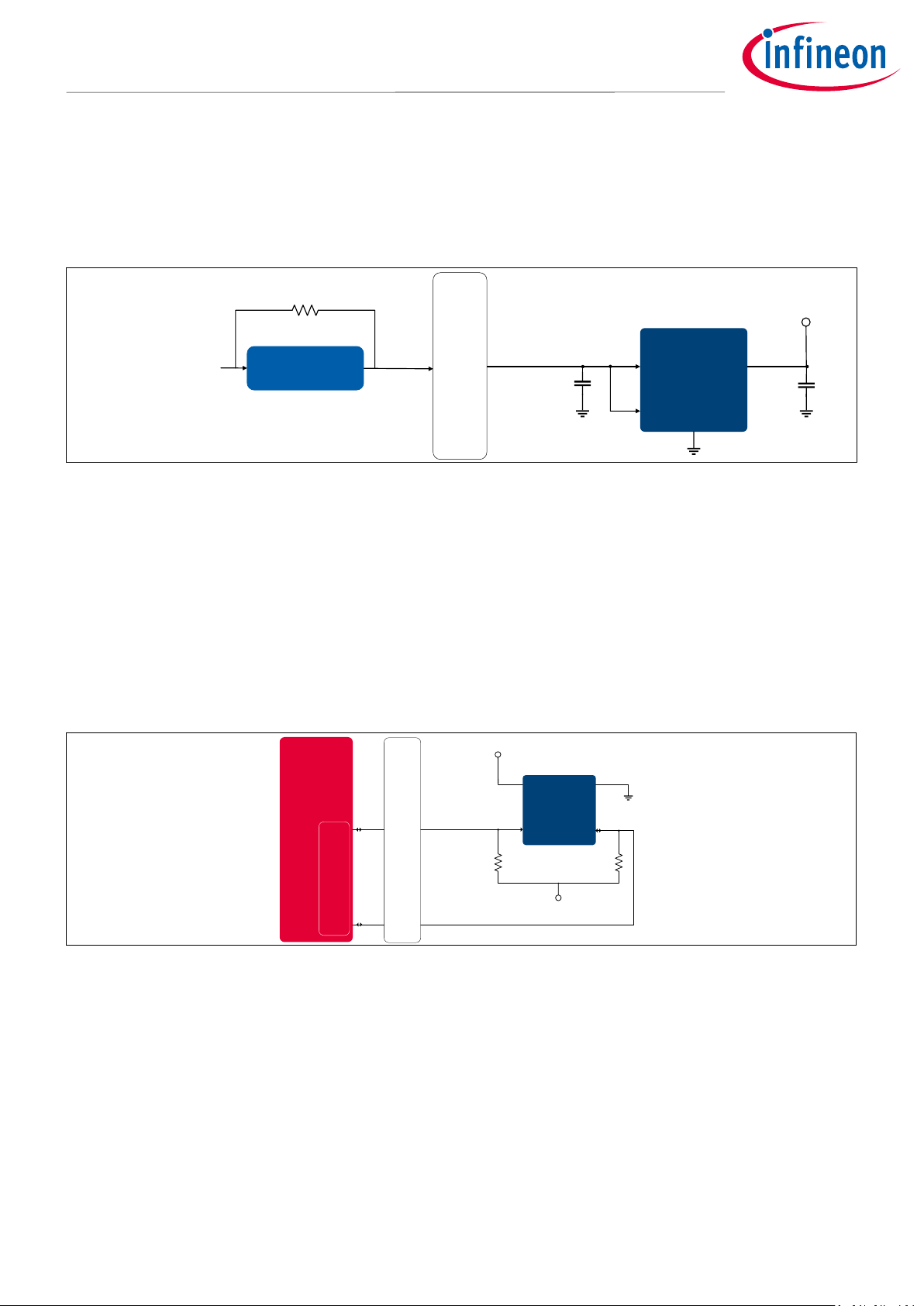
4.3 Power supply
The Radar Baseboard XMC4700 is powered via micro-USB connector, external 7 V power supply or LiPo battery.
It also provides the supply for the BGT24LTR11 Shield via the connectors. An LDO (U6) is used on the
BGT24LTR11 Shield to supply all the components. Figure 7 shows the power supply concept used in the system.
LDO
VCC = 3.3 V
VCC1 IN OUT
EN
4.7 µF 1 µF
C41 C42
Connectors b/w Base Board and
Radar Shield
Micro USB /
External supply /
LiPo battery
Rshunt
Current sensors VCC1
5 V
Figure 7 Block diagram –power supply concept
4.4 EEPROM
The BGT24LTR11 Shield contains an EEPROM (U7) to store data such as a board identifier. The Serial Data (SDA)
is a bi-directional pin that is used to transfer addresses and data into and out of the device. The Serial Clock
(SCL) is an input that is used to synchronize the data from and to the device.
When the Shield is plugged into the Radar Baseboard XMC4700, the sensor’s supplies are initially deactivated.
Only the EEPROM is powered. The MCU reads the content of the EEPROM’s memory to determine which Shield
is plugged into the interface. Only when the board has been correctly identified are the sensor’s supplies
activated.
EEPROM
VCC
VCC VSS
SCL
Connectors b/w Base Board and
Radar Shield
SDA
I2C_EEPROM.SCL
I2C_EEPROM.SDA VCC
R83 R84
USIC
XMC4700
Figure 8 EEPROM block diagram
4.5 RF front end Shield
Figure 9 shows the top view of the RF front end. The RF front end has a cover with absorber material to get the
best RF performance. The transmitter and receiver inputs of the BGT24LTR11 are single-ended. The TX output
and RX input are connected over a matching structure, a DC block and a feed-through via to the antennas on
the other side of the board. The isolation between the RX and TX ports is improved by adding a grounded
length of line at the ground pins next to the TX output pin, as shown in Figure 9.

Application Note page 16 of 32 V1.0
2021-03-31
Distance2GoL (Software-Controlled FMCW) low-power radar shield using
BGT24LTR11 for range detection and human tracking
Hardware description: BGT24LTR11 Shield
Radar front-end
shielding
DC blocks
Harmonics
filter
BGT24LTR11
Compensation
structures (stubs)
RX TX
Figure 9 RF front-end overview (top)
4.6 BGT24LTR11 – 24 GHz transceiver MMIC
The heart of the sensor module is the highly integrated BGT24LTR11 24 GHz transceiver IC. Figure 10 shows the
detailed block diagram of the MMIC. BGT24LTR11 is a radar MMIC for signal generation and reception,
operating in the 24.000 GHz to 24.250 GHz ISM band. It is based on a 24 GHz fundamental Voltage Controlled
Oscillator (VCO).
Figure 10 Block diagram –BGT24LTR11 MMIC
A built-in voltage source delivers a VCO PTAT tuning voltage. When connected to the VCO tuning pin, it
compensates for the inherent frequency drift of the VCO overtemperature, thus stabilizing the VCO within the
ISM band and eliminating the need for a PLL/microcontroller.
The receiver section uses a Low Noise Amplifier (LNA) in front of a quadrature homodyne down-conversion
mixer to provide excellent receiver sensitivity. Derived from the internal VCO signal, a RC Poly-Phase Filter (PPF)
generates quadrature LO signals for the quadrature mixer. I/Q IF outputs are available through single-ended
terminals.

Application Note page 17 of 32 V1.0
2021-03-31
Distance2GoL (Software-Controlled FMCW) low-power radar shield using
BGT24LTR11 for range detection and human tracking
Hardware description: BGT24LTR11 Shield
4.7 Antennas
The BGT24LTR11 Shield features a 4 x 1 array antenna for the transceiver and receiver sections. The antenna
has a gain of 9.6 dBi and an opening angle of 28.5 x 81.8 degrees. Figure 11 shows the simulated 2D and 3D
radiation pattern.
z
x
y
Figure 11 Simulated radiation pattern for 4x1 antennas
Application Note page 18 of 32 V1.0
2021-03-31
Distance2GoL (Software-Controlled FMCW) low-power radar shield using
BGT24LTR11 for range detection and human tracking
Hardware description: BGT24LTR11 Shield
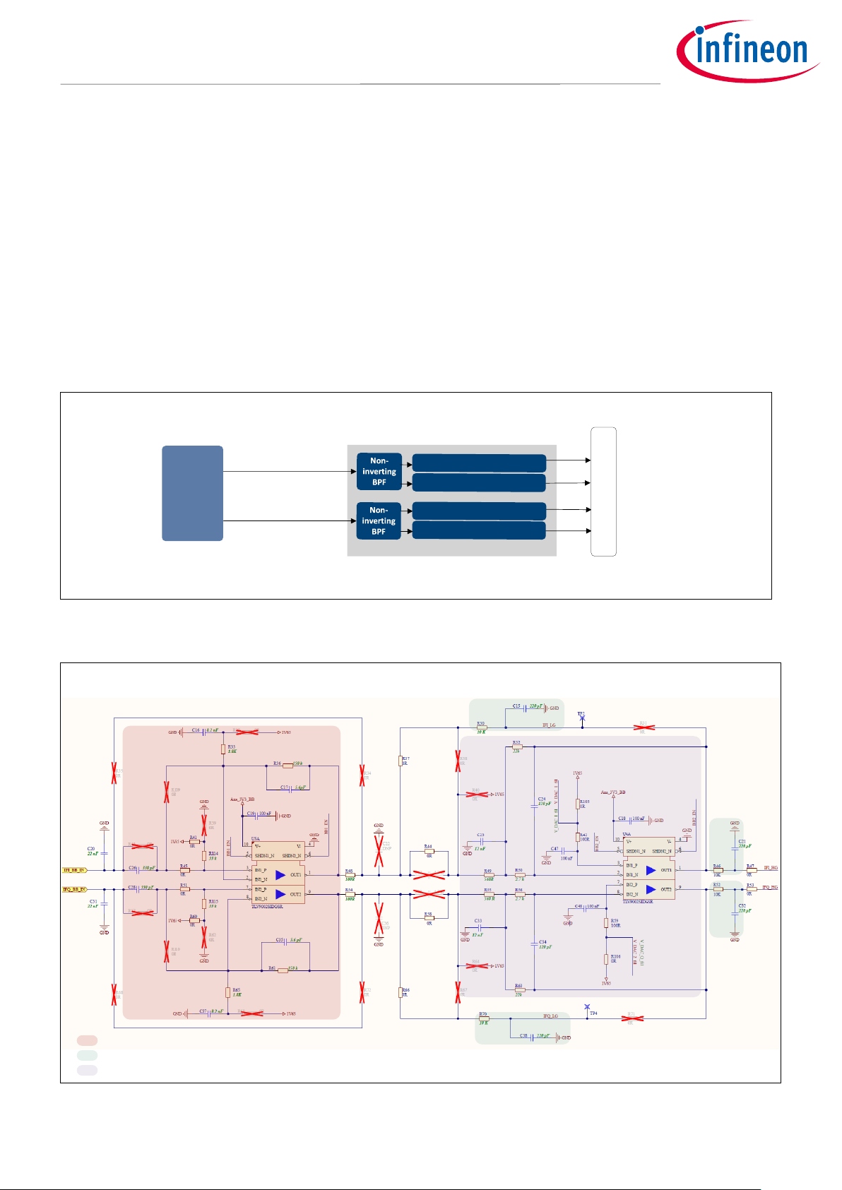
4.8 Analog baseband section
The BGT24LTR11 provides both in-phase and quadrature-phase Intermediate Frequency (IF) signals from its
receiver. Depending on the target in front of the radar antennas, the analog output signal from the BGT24LTR11
chipset can be very low in amplitude (µV to mV range). To process these low-amplitude signals, it is necessary
to amplify the IF signals.
The BGT24LTR11 Shield offers two stages of signal amplification using low-noise op-amps. As shown in Figure
12 and Figure 13, the I/Q outputs of the BGT are filtered and amplified in the first gain stage. The second gain
stage consists of a multiple-feedback active filter topology, which provides additional gain and bandpass
filtering to the output of the first gain stage. The low-gain and high-gain output signals are low-pass filtered to
avoid aliasing. A voltage divider is used to create the 1.65 V reference voltage. Both stages of op-amps are duty
cycled for low power consumption.
IFI_LG
IFI_HG
IFQ_LG
IFQ_HG
Base band section
IFI
IFQ
BGT24LTR11
Connector to
Radar Baseboard XMC4700
LP anti-aliasing filter
Multiple feedback LPF
LP anti-aliasing filter
Multiple feedback LPF
Figure 12 Baseband amplifier chain –block diagram
Non-inverting BPF
Multiple feedback LPF
LP anti-aliasing filter
Figure 13 Baseband amplifier chain –schematic

Application Note page 19 of 32 V1.0
2021-03-31
Distance2GoL (Software-Controlled FMCW) low-power radar shield using
BGT24LTR11 for range detection and human tracking
Hardware description: BGT24LTR11 Shield
The offset of the low-gain signal equals the static offset of the BGT output signals. Due to the DC block at the
beginning of the second stage, the offset of the high-gain signal matches the reference voltage of 1.65 V. As
shown in Figure 14, the first gain stage provides a gain of up to 30 dB (low-gain stage) and both the stages
together provide a gain of up to 57 dB (high-gain stage).
Figure 14 Baseband frequency response for low-gain and high-gain stages
Figure 14 shows the frequency response of the low- and high-gain stages. The BGT24LTR11 Shield allows the
user to select either the low-gain (first stage only) or high-gain (first stage + second stage) mode depending on
the target RCS and distance to be detected. The low-gain output is referenced to the individual mixer output
bias voltage (1.6 to 2.0 V), and the high-gain stage is AC coupled and referenced to VCC/2 = 1.65 V.
Table 2 lists the MCU pins (on the Radar Baseboard XMC4700) associated with each of the gain stages. Use the
graphical pin select tool in the DAVE™ software to select the appropriate pins for signal processing.
Table 2 Baseband amplifier to MCU pin connections
XMC4700 –port pin
Pin label
Pin function
P14.6 (VADC.G0CH6)
IF.I1
IFI –high gain
P14.7 (VADC.G0CH7) / P14.3 (VADC.G1CH3)
IF.Q1
IFQ –high gain
P14.14 (VADC.G1CH6) / P15.3 (VADC.G2CH3)
IF.I2
IFI –low gain
P14.15 (VADC.G1CH7) / P15.9 (VADC.G3CH1)
IF.Q2
IFQ –low gain
The gain and bandwidth of the IF stages can be manually configured by the user by changing the resistor and
capacitor values specified in Table 3.
Table 3 Baseband amplifier components and settings
IF stage
Designator
Gain
Configurable components –
I section
Configurable components
–Q section
Stage 1
(low gain)
U5A
30 dB
C16, R33, C17, R36
C37, R65, C35, R61

Application Note page 20 of 32 V1.0
2021-03-31
Distance2GoL (Software-Controlled FMCW) low-power radar shield using
BGT24LTR11 for range detection and human tracking
Hardware description: BGT24LTR11 Shield
IF stage
Designator
Gain
Configurable components –
I section
Configurable components
–Q section
Stage 1 + Stage 2
(high gain)
U5A + U4A
57 dB
All components as
mentioned for Stage 1 +
R49, R50, R32, C23, C24
All components as
mentioned for Stage 1 +
R55, R56, C34, R63, C33
4.8.1 IF section and FMCW ramp settings
The bandpass characteristics of the IF section are also determined from the FMCW ramp parameter settings.
Different ramp settings result in different IFs for targets at different distances. The baseband section is
designed to meet the required IF cut-offs. Table 4 gives an example of IFs produced by stationary targets at
particular distances corresponding to different sawtooth-type ramp parameters. These IFs are also called “beat
frequencies”. The beat frequencies calculated in the table do not include the Doppler shift.
The is calculated from the following formula:
Where
= target distance in meters (m)
= ramp bandwidth in Hertz (Hz)
= ramp time in seconds (s)
= speed of light in meters/second (m/s)
Table 4 IF vs. FMCW ramp parameters vs. target distance
Ramp duration
(Tr) (µs)
Ramp
bandwidth
(Δf) (MHz)
Beat frequency (Fb) (kHz)
Target at 50 cm (R)
Target at 10 m (R)
Target at 30 m (R)
1000
180
0.60
12.00
36.00
1000
200
0.67
13.33
40.00
1500
180
0.40
8.00
24.00
1500 (default)
200
0.44
9.00
26.70
2000
180
0.30
6.00
18.00
2000
220
0.33
6.70
20.00
Other manuals for BGT24LTR11
1
Table of contents
Other Infineon Transceiver manuals


