Infinite Transtector DCIPS2B-S-00-B11 User manual

Installation Manual
© 2020 Innite Electronics, Inc. Transtector is a registered trademark of Innite Electronics, Inc. | DCIPS2B-M Rev. 1
DCIPS2B-S-00-B11 Power Supply System

Installation Manual | DCIPS2B-S-00-B11 Power Supply System
23
+1 (208) 635-6400 | www.transtector.com +1 (208) 635-6400 | www.transtector.com
Copyright © 2020 TRANSTECTOR
All Rights Reserved
Restricted Rights Legend:
Use, duplication, or disclosure by the Government is subject to restrictions as set forth in
subparagraph © (1)(ii) of the Rights in Technical Data and Computer Software clause at DFARS
252.227-7013 or subparagraphs © (1) and (2) of Commercial Computer Software - Restricted
Rights at 48 CFR 52.227-19, as applicable.
For Contact Information, please go to www.transtector.com/contact-us/
Refer to the TRANSTECTOR License Agreement in this package before installing or using this
product.
Unless specically noted, all addresses, data characters and persons referenced herein, and all
examples involving names of companies and products, are ctitious examples and are designed
solely to illustrate the use of TRANSTECTOR products.
Product names, logos, brands, and other trademarks featured or referred to within this product
manual are the property of their respective trademark holders. These trademark holders are not
aliated with TRANSTECTOR or our products. They do not sponsor or endorse our products.
LIMITATIONS AND AUTHORIZATIONS FOR USE AND PERMITTED APPLICATIONS
TRANSTECTOR’s products are not designed, intended for use in, or authorized for use as
critical components in, human life support systems/equipment, equipment used in hazardous
environments, or equipment used in nuclear control equipment or systems. Any such use requires
the prior express written consent of an authorized executive ocer of TRANSTECTOR, which
consent may be withheld by TRANSTECTOR in its sole discretion. Users assume all risk and
liability for, and agree to indemnify and defend TRANSTECTOR from and against any claims for
personal injury (including death) or property damage resulting from any such use or application
which is made in the absence of such prior express written consent.
If you nd errors or problems with this documentation, please notify TRANSTECTOR.
TRANSTECTOR does not guarantee that this document is error-free. The information in this
document is subject to change without notice.
Contents
Chapter 1 About This Manual
1.1 Objectives.............................................................................................................................6
1.2 Audience...............................................................................................................................6
1.3 Document Key......................................................................................................................6
1.4 Product Support....................................................................................................................7
Chapter 2 System Description
2.1 Overview...............................................................................................................................8
2.2 System Parameters............................................................................................................11
2.3 System Components..........................................................................................................13
2.3.1 System Controller ...................................................................................................13
2.3.2 DC Distribution Unit................................................................................................13
2.3.3 Rectier Module......................................................................................................14
Chapter 3 System Safety
3.1 Safety Warnings and Guidelines ........................................................................................15
3.1.1 System Markings ....................................................................................................15
3.1.2 Safety Recommendations.......................................................................................15
3.1.3 Installation Warning ................................................................................................16
3.1.4 Restricted Access Area Warnings...........................................................................16
3.1.5 System Enclosure...................................................................................................16
3.1.6 Operating Temperature Warnings...........................................................................16
3.1.7 Electrical Safety Warnings......................................................................................16
3.1.8 Grounding...............................................................................................................18
3.1.9 Batteries..................................................................................................................18
3.1.9.1 Lead Acid Batteries.....................................................................................18
3.1.10 In Case of an Accident............................................................................................19
3.2 Caution ...............................................................................................................................19
3.2.1 Storage and Transportation ....................................................................................19
3.2.2 Disposal..................................................................................................................19
3.2.3 Handling Electrostatic Sensitive Devices................................................................19
3.2.4 Traceability..............................................................................................................19
3.2.5 Breakers..................................................................................................................20
3.2.6 Hot Surfaces...........................................................................................................20
Chapter 4 Installation Guide
4.1 Preparation.........................................................................................................................21
4.1.1 Installation Overview...............................................................................................21
4.1.2 Unpacking...............................................................................................................21
4.1.3 Tools........................................................................................................................22
4.1.4 Cable Size...............................................................................................................23
4.2 Rack Mounting....................................................................................................................24
4.3 Cable Entry.........................................................................................................................26
4.3.1 Remove Top Cover.................................................................................................26
4.3.2 Cable Entry Openings.............................................................................................27
REV DESCRIPTION CHK’d & APPR’d / DATE
1 Initial Release DWR / 09-15-20

Installation Manual | DCIPS2B-S-00-B11 Power Supply System
45
+1 (208) 635-6400 | www.transtector.com +1 (208) 635-6400 | www.transtector.com
FIGURES
Figure 2-1 Power System Overview..............................................................................................8
Figure 2-2 Principal of Operation...................................................................................................9
Figure 2-3 Power System With Extended Rear and Top Cover Kit.............................................10
Figure 2-4 Power System with Rear and Top Cover Kit..............................................................10
Figure 2-5 DCIPS2-3000 Rectier...............................................................................................14
Figure 4-1 System Mounting - Cabinet........................................................................................24
Figure 4-2 System Mounting - Open frame / relay rack...............................................................25
Figure 4-3 Remove Top Cover ....................................................................................................26
Figure 4-4 Remove Extended Cover Kit......................................................................................27
Figure 4-5 Cable Entry Options...................................................................................................27
Figure 4-6 Grounding Connection...............................................................................................28
Figure 4-7 Grounding Connection with Rear & Top Cover Kit.....................................................28
Figure 4-8 Grounding Connection with Extended Rear Cover Kit - Two Point............................29
Figure 4-9 Grounding Connection with Extended Rear Cover Kit - Single Point ........................29
Figure 4-10 AC Cable Connection (1-phase) ..............................................................................30
Figure 4-11 AC Cable Connection (3W+N+PE)...........................................................................31
Figure 4-12 AC Cable Connection in North American (3W+PE) .................................................31
Figure 4-13 DC Load Connection................................................................................................32
Figure 4-14 Battery Connection...................................................................................................33
Figure 4-16 ACX External Board.................................................................................................34
Figure 4-17 ACX Relay Board.....................................................................................................35
Figure 4-18 Alarm Connection.....................................................................................................36
Figure 4-19 2-block Symmetry Measurement (for illustration only).............................................37
Figure 4-20 4-Block Symmetry Measurement (for illustration only).............................................37
Figure 4-21 Temperature Sensor Connection .............................................................................38
Figure 4-22 RS232 Connection...................................................................................................39
Figure 4-23 Rectier Installation..................................................................................................39
Figure 7-1 Unlocking and Removing the Controller.....................................................................51
Figure 7-2 Replacing a Surge Protection Module........................................................................52
TABLES
Table 4-1 Recommended Electrical Cable Size ..........................................................................23
Table 5-1 Float/Boost Charge Voltages.......................................................................................43
Table 5-2 Commissioning Record................................................................................................45
Table 6-1 Connection Torque Setting Check...............................................................................46
4.4 Grounding Connection........................................................................................................28
4.5 AC Input Connection ..........................................................................................................29
4.6 DC Load Connection..........................................................................................................32
4.7 Battery Connection.............................................................................................................33
4.8 Alarm and Signal Connections...........................................................................................34
4.9 Symmetry Connection ........................................................................................................36
4.10 Temperature Sensor Connection........................................................................................37
4.11 Connecting an RS232 Communication Cable....................................................................38
4.12 Rectier Installation ............................................................................................................39
4.13 Reinstalling Top Cover........................................................................................................40
Chapter 5 Commissioning
5.1 Commissioning Overview...................................................................................................41
5.2 Tools and Test Equipment...................................................................................................41
5.2.1 Tools List.................................................................................................................41
5.2.2 Test Equipment.......................................................................................................41
5.3 Preparation.........................................................................................................................41
5.4 Commissioning procedure..................................................................................................42
5.5 Test of output voltage .........................................................................................................43
5.5.1 Float charge (U1)....................................................................................................43
5.5.2 Adjustment of Float Charge, U1..............................................................................43
5.5.3 Boost charging (U2) (if applicable)..........................................................................43
5.6 Battery supervision.............................................................................................................44
5.7 Battery test .........................................................................................................................44
5.8 Commissioning record........................................................................................................45
Chapter 6 Maintenance & Troubleshooting
6.1 Maintenance.......................................................................................................................46
6.1.1 Checking Terminal Connection...............................................................................46
6.1.2 Other Requirements................................................................................................46
6.2 Troubleshooting..................................................................................................................47
Chapter 7 Replacing Modules
7.1 Controller Replacement......................................................................................................51
7.2 Rectier Replacement ........................................................................................................51
7.3 Battery and Load Breakers Replacement...........................................................................52
7.4 Surge Protection Device Replacement...............................................................................52
Appendix A - Drawings
A.1 System Layout ......................................................................................................................53
A.2 Installation Details - Connections..........................................................................................54
A.3 Block Diagram.......................................................................................................................55
A.4 Detailed Dimensions.............................................................................................................56

Installation Manual | DCIPS2B-S-00-B11 Power Supply System
67
+1 (208) 635-6400 | www.transtector.com +1 (208) 635-6400 | www.transtector.com
1. About This Manual
This chapter contains an overview of the information that is presented in this Power
System Manual. This includes information on objectives, the intended audience, and the
organization of this manual. In addition, this chapter also denes the conventions used to
indicate warnings, cautions and noteworthy information.
1.1 Objectives
This manual describes the Power System, explains how to unpack and install the system,
how to perform the initial power-up and operational system check.
The information presented in this document is current as of the publication date.
1.2 Audience
This manual is to be used by installers and technicians who are preparing the site for a
new installation and installing the power system. This manual assumes that the technician
has an understanding of power systems in general and understands safety procedures for
working around AC and DC voltage.
The user of this document should be familiar with electronic circuitry and wiring practices
and have some expertise as an electronic, power, or electromechanical technician.
1.3 Document Key
This manual uses the following conventions:
WARNING This symbol indicates a situation that could cause bodily injury.
Always be aware of hazardous conditions when working in or around the
power system.
CAUTION This symbol indicates a situation that might result in equipment
damage. The reader should be aware that their actions could result in
equipment or data loss.
NEED MORE INFORMATION? This symbol is used to reference
information either in this manual or in another document.
NOTE This symbol means the reader should take note. Notes are helpful
suggestions or reminders.
Chapter 1 About This Manual
Table 1-1 Abbreviations
Abbreviation Description
ACX Advance Controller Card
FMD Fan-cooled Modular Power Converter
FMP Fan-cooled Modular Power Rectier
LVD Low voltage disconnection
MCB Miniature circuit breaker
PCC Prime Controller Card
PLD Partial load disconnection
SLI SLI Inverter
1.4 Product Support
Product support can be obtained using the following addresses and telephone numbers.
Phone: +1-208-635-6400
Web site: www.transtector.com
When contacting TRANSTECTOR, please be prepared to provide:
1. The product model number, spec number, S build number, and serial number
- see the equipment nameplate on the front panel
2. Your company’s name and address
3. Your name and title
4. The reason for the contact
5. If there is a problem with product operation:
• Is the problem intermittent or continuous?
• What revision is the rmware?
• What actions were being performed prior to the appearance of the problem?
• What actions have been taken since the problem occurred?
1.5 Disclaimer
TRANSTECTOR is not responsible for system problems that are the result of installation or
modication of the instructions provided in this manual.

Installation Manual | DCIPS2B-S-00-B11 Power Supply System
89
+1 (208) 635-6400 | www.transtector.com +1 (208) 635-6400 | www.transtector.com
2.1 Overview
This chapter contains an overview of the system and a short description of the units in the
system.
The DCIPS2B 2U power system is designed to meet the requirements of modern
telecommunications equipment. This power solution provides rectication, system
management and power distribution. The power system utilizes fan-cooled, hot-swappable
fan-cooled, hot-swappable rectier modules DCIPS2-3000; each with an output of up to
2900W.
The power system can be managed locally through messages and alarms displayed on
the LCD screen of system controller, or remotely using the PC-based PowCom™ software
package.
The power system contains 3 rectier positions and modules depending on your order, one
system controller, and distribution unit.
The DCIPS2B 2U system consists of:
1. System Controller
2. Rectier module
Chapter 2 System Description
3. Load and Battery Distribution
4. AC Surge Protection Device (Option)
5. AC Input Terminal Block
6. DC Connection Busbars
7. Alarm Interface Board
4
5
3
7
2
6
1
Figure 2-1 Power System Overview
The DCIPS2B 2U is capable of delivering up to 8.8kW steady state power to the combined
load and batteries. The maximum power available to the load is 10.4kW. The system is
based on hot-swappable 48V rectier modules which are working in parallel with automatic
load sharing.
The power system is normally congured with N+1 redundancy, with N as the number of
rectier modules necessary for feeding the load and charging the battery and 1 as the
redundant rectier module. In normal operation the rectier modules are used to feed the
load and simultaneously maintain the batteries in a fully charged state.
Once the mains input power is failed, the rectiers are shut down and the batteries feed
the load immediately. If the battery voltage drops below a preset level, the Low Voltage
Disconnection(LVD)circuitdisconnectsthebatteriesautomaticallytopreventover-discharge
of the battery to prolong battery life. When the mains input power is restored, the rectiers
will start up automatically to feed the load, close LVD circuit and recharge the batteries.
System performance is supervised and controlled by the controller, PCC orACXAdvanced.
The DC output voltage, alarm thresholds, LVD circuit operation, temperature compensated
battery charging can be set by the controller. Any malfunction will be indicated by LED, text
in the display and operation of dry contacts.
However, the system controller is not a single point of failure. In the event of controller
malfunction, basic tasks like feeding the load and charging batteries will be maintained by
the rectier modules directly at preset default values.
The alarm and threshold setting of the power system can be set either through the buttons
and operation menu on the local controller, or remotely through the PowCom™ supervision
software.
Battery Breaker
Battery
LVBD
Load Breakers
DC Distribution
AC Rectifier
Rectifier
Controller
Figure 2-2 Principal of Operation

Installation Manual | DCIPS2B-S-00-B11 Power Supply System
10 11
+1 (208) 635-6400 | www.transtector.com +1 (208) 635-6400 | www.transtector.com
To meet the requirements of dierent application, there are two kinds of Rear and Top Cover
Kit available:
• Rear and Top Cover Kit for cabinets
• Extended Rear and Top Cover Kit for open relay racks.
AC Cable Entry
Top Cover
AC Input Cover
Extended Rear Cover
DC Cable Entry
Figure 2-3 Power System With Extended Rear and Top Cover Kit
NOTE The cable entry on the rear of the shelf is factory supplied and opened. If you want
to route the cables from the bottom or side, remove the knockouts. For AC cable entry,
you have to install the supplied PG21.
AC Cable Entry
Top Cover
Rear Cover
Figure 2-4 Power System with Rear and Top Cover Kit
NOTE The Rear and Top Cover Kit and Extended Rear and Top Cover Kit are optional
components and just provided according to your order.
2.2 System Parameters
OUTPUT
Power (max) 5.4kW load + 3.5kW battery charge @ 230/400VAC nominal
8.7kW load + 1.9kW battery charge @ 120VAC nominal
Output Current (max) 100A load + 65A battery charge @ 230/400VAC nominal
70A load + 35A battery charge @ 120VAC nominal
Voltage 44-57.6VDC
INPUT
Voltage Range 100-120VAC, 1W+N+PE, 50/60Hz
200-240VAC, 2W+PE, 50/60Hz
208-240/360-416VAC, 3W+N+PE, 50/60Hz
Frequency 47-63Hz
Input Current 1-phase 50A @ 100-120VAC, 39A @ 200-240VAC
3-phase 13A per phase @ 230/400VAC
Power factor >0.98
Surge Protection Optional
DC DISTRIBUTION & BATTERY MANAGEMENT
Battery Breakers 1 or 3 x 80A, 100A or 125A
Symmetry Inputs Up to 6
Programmable LVD / PLD 125A (voltage) / 125A (voltage/time)
Load Breakers 5 x 18mm / 6 x 13mm, depending on number of battery breakers.
Ratings
(see datasheet for details) single pole - 4A, 6A, 10A, 16A, 20A, 25A, 32A, 40A, 50A, 63A
two pole - 80A, 100A; three pole - 125A, 150A
MONITORING AND CONTROL
Controller PCC or ACX Advanced
Local Interface 4 x 20’ LCD, 4-key menu, USB (ACX only) and RS232
Remote Interface Ethernet / Modem using PowCom™ software
Visual Indication Green LED - System On
Yellow LED - Message(s)
Red LED - Alarm(s)
Analog Inputs 12 x voltage inputs (range 0-100VDC) - 6 max. for symmetry
Alarm Outputs 4 x potential free relays (C, NC, NO)
Digital Inputs 2 x, Logic 0: U<10VDC, Logic 1: U>12VDC (ACX only)
Digital Outputs 2 x, open collector type (ACX only)
Temperature measurement 2 x Temperature probe (Battery, Ambient)
CONNECTIONS
Battery connections M8 lugs, +Ve common from bus bar
AC connections Max. 7AWG/10mm2, screw type connector
Load breaker connections -Ve termination direct to breakers, +Ve common from busbar
11AWG/4mm²
Alarm connections Max. 14AWG/1.5mm², screw type connector

Installation Manual | DCIPS2B-S-00-B11 Power Supply System
12 13
+1 (208) 635-6400 | www.transtector.com +1 (208) 635-6400 | www.transtector.com
MECHANICAL
Dimensions (WxHxD) 19” (483mm) x 3.5” (88mm) x 16.8” (428mm) std cover | 19.7”
(500mm) ext. cover
Weight of the system
(fully equipped) 47lbs (21.3kg)
Mounting Options 19” / Mid-mount
Cable Entry Rear Access (top/rear covers have to be removed to make some
connections)
STANDARD COMPLIANCE / ENVIRONMENTAL
EMC and Immunity EN 300 386 ; EN61000-6-3 (Emission) ; EN61000-6-2 (Immunity)
Safety IEC60950-1:2005 2 Ed. +A1:2009
Environment Storage: ETS300 019-2-1, Transport: ETS300 019-2-2, Operation
ETS300 019-2-3, Damp Heat: IEC60068-2-78
Operating Temperature -40°C to +65°C (derated above 55°C)
Storage Temperature -40°C to +85°C
RECTIFIER MODEL DCIPS2-3000
Eciency 95%
Input Current (max) <17.0A
Output Current
(53.5V oat)
54.2A
Output Power 1700W @ >180VAC
2900W @ 90-180VAC
Operating Temperature
(without derating) 55°C
Input Voltage
(Nominal 100-240VAC) 85-300VAC
Output Voltage 44-57.6VDC
Load sharing < 5% of nominal current
Dimensions (HxWxD) 1.6 (41) x 4.2 (107) x 14 (355) ”(mm)
Weight 4.6lbs / 2.1kg
Cooling Fan-cooled, speed controlled
Protection Short circuit, automatic current/power limiting,
input/output overvoltage, thermal
Alarms Fan failure, Short circuit/arcing protection,
High temperature/output voltage Low output voltage,
Input voltage out of range Low fan speed (warning)
Internal communication failure
LED Indication Green: AC normal operation
Yellow: Steady - Low fan speed, High temperature
Flashing - Communications failure
Red: Module alarm / shutdown
Audible noise <45dBA @ ≤25°C (50% load) | <60dBA (100% load)
2.3 System Components
With the exception of the rectier modules the DCIPS2B 2U system is delivered with all
components mounted according to the ordered conguration. The main components are
described below and in later chapters of this manual.
2.3.1 System Controller
The DCIPS2B power system is controlled by the ACX Advanced controller. The
description and operation of this controller is covered in a separate manual which is
available at: www.transtector.com
2.3.2 DC Distribution Unit
The distribution unit includes congurable load breakers, battery breakers, a shunt for
battery current measurement and fuse alarms for load and battery breakers.
The distribution unit has no special operation other than switching the load and battery
breakers on and o. All trip states of breakers are supervised by measuring the voltage
drop across each breaker.
Breakers that are not connected to any load will not cause a breaker alarm even if they
are left open.
A battery fuse alarm may not be triggered instantly when a battery breaker is o. The
alarm is triggered only when the voltage drop between the system voltage and the
battery voltage is more than 1.5V. The interval that the voltage drop increases to 1.5V
depends on the battery status.
Dueto asmallleakage current(2.5-3mA)through thealarmcircuit, thevoltagemeasured
with a Digital Volt Meter (DVM) on an open breaker output will be nearly equal to the
rectier output voltage.
The distribution module has common “+Ve” with load breakers in “-Ve” leg. For more
information see schematic drawing in Appendix A - Drawings.
2.3.2.1 Low Voltage Disconnect (LVD) and Dummy LVD
Generally, thesystemis equipped withlowvoltage battery disconnection,whichprevents
the batteries from deep discharging, thus prolonging the battery life. A disconnection
requires a detected mains failure at the supervision unit.
If disconnection occurs, the batteries will not supply power to the load until they have
been recharged to set voltage level, which can be adjusted by the user.
If disconnection occurs, the batteries will be reconnected when mains supply returns.
AdummyLVDcanalsobeinstalledintothepowersystemiftheLowVoltageDisconnection
function is not needed.

Installation Manual | DCIPS2B-S-00-B11 Power Supply System
14 15
+1 (208) 635-6400 | www.transtector.com +1 (208) 635-6400 | www.transtector.com
2.3.2.2 Partial Load Disconnection / Load Shedding (PLD)
Partial load disconnection can be congured to be voltage or time dependent, this is
selected when ordering the power system.
At a mains outage the controller will open the PLD contactor when the batteries have
discharged to a certain voltage or if the battery voltage has been under a certain voltage
for a predetermined time. The disconnection has to be set according to the present load
and battery manufacturer’s discharge tables or requirements.
2.3.3 Rectier Module
The fan-cooled rectier converts the AC input to -48VDC output for loads and batteries. It
is designed for parallel operation and plug-in installation in the power shelf and supplies
extremely stable DC power.
Each rectier incorporates an internal microprocessor that sends frequent updates to the
system controller and adjacent rectiers. This ensures accurately controlled load sharing
among rectiers and supplies status and identication information to the controller.
The rectier module features two LEDs for status indication, thermal protection with
power derating, and input over voltage disconnection with automatic reset. The rectier
module is hot-swappable and can be quickly removed and replaced without disrupting
the system or load.
Handles
Cooling Fans
Status LEDs
Figure 2-5 DCIPS2-3000 Rectier
Chapter 3 System Safety
3.1 Safety Warnings and Guidelines
Thefollowingwarningsandguidelinesshouldbefollowedbyproperlytrainedand authorized
personnel when installing, operating, commissioning or maintaining this equipment.
Neglecting the instructions may be dangerous to personnel and equipment.
3.1.1 System Markings
The following markings are found on the Power System:
Ground Symbol
DC Ground Symbol
Product Label - The product label contains the system part number, model number, system
ratings and safety approvals. The label is located inside the system.
Safety Label - The safety label is located inside the system.
3.1.2 Safety Recommendations
Any device that uses electricity requires proper guidelines to ensure safety.
• The Power System should only be installed or serviced by a qualied personnel.
• Always keep tools away from walkways and aisles. Tools present a tripping hazard
in conned areas.
• Keep the system area clear and dust-free during and after the installation.
• Always know the location of emergency shut-o switches in case of an accident.
• Always wear appropriate eye protection and use appropriate tools for working with
high voltage equipment.
• Do not perform any action that creates a potential hazard to other people in the
system area.
• Never work alone in potentially hazardous conditions.
• Always check for possible hazards before beginning work.
• Remove watches, rings and jewelry that may present a hazard while working on the
power system.

Installation Manual | DCIPS2B-S-00-B11 Power Supply System
16 17
+1 (208) 635-6400 | www.transtector.com +1 (208) 635-6400 | www.transtector.com
3.1.3 Installation Warning
Thefollowingsafetyguidelinesshouldbeobservedwhentransportingor moving the system:
• Before moving the Power System, read the system specications sheet to determine
whether the install site meets all the size, environmental, and power requirements.
• The system should only be moved by qualied personnel and equipment.
• The Power System should be properly mounted to the building structure at the install
location to prevent bodily injury.
• Installation of the equipment in the rack should be properly installed so that hazardous
conditions are not present due to uneven loading.
• When installing the system in a rack, allow adequate room to prevent blocking of the
vent openings on the power equipment and to allow for optimal air circulation and to
reduce the chance of system overheating.
3.1.4 Restricted Access Area Warnings
The Power System is designed for installation in locations with restricted access often
secured by a locking mechanism. It can therefore be accessed only by a trained service
person, who is fully aware of the restrictions applied to the location, or by an authority
responsible for the location.
3.1.5 System Enclosure
Appropriate measures need to be taken to avoid intrusion of any unwanted objects or insects
into conductive areas of the power system as there is a potential risk of system damage.
Disclaimer: TRANSTECTOR assumes no liability or responsibility for system failures
resulting from inappropriate enclosure around the system.
3.1.6 Operating Temperature Warnings
To prevent the Power System from overheating, an automatic shutdown mechanism has
been installed. It is not recommended to continually operate the Power System in an area
that exceeds the maximum recommended operating temperature.
3.1.7 Electrical Safety Warnings
The following are electrical safety recommendations for working near the Power System:
WARNING Observe low voltage safety precautions before attempting to work on the
systemwhenpowerisconnected.Potentiallylethalvoltagesarepresentwithinthesystem.
WARNING Caution must be exercised when handling system power cables. Damage to
the insulation or contact points of cables can cause contact with lethal voltages. For safety
reasons, cables should be connected to the power system before power is applied.
• Remove all metallic jewelry like watches or rings that may present a hazard while
working on the power system.
• Before connecting the AC input source to the power system, always verify voltage.
• Verify the AC source capacity. See system specications for AC information.
• All AC connections must conform to local codes and regulations, e.g. ANSI, CEC,
NEC, etc.
• When makingAC connections, allAC power and DC load distribution breakers should
be in the OFF position.
• All circuit breakers should meet the original design specications of the system. In
addition, equipment connected to the system should not overload the circuit breakers
as this may have a negative eect on overcurrent protection and supply wiring,
causing system or user harm.
• Verify the DC capacity before making connections. See system specications for DC
information.
• Potentiallylethalvoltagesarepresentwithinthesystem. Ensurethatallpowersupplies
are completely isolated by turning all power switches OFF, disconnecting all relevant
connectors and removing all relevant breakers before attempting any maintenance
work. Do not rely on switches alone to isolate the power supply. Batteries should
also be disconnected.
• Potentially lethal voltages are present within this system. Ensure that low voltage
safety requirements are implemented before attempting to work on the system with
power connected.
• Potentially lethal voltages can be induced if the equipment is not grounded (earthed)
correctly. Ensure that all ground connections are secure.

Installation Manual | DCIPS2B-S-00-B11 Power Supply System
18 19
+1 (208) 635-6400 | www.transtector.com +1 (208) 635-6400 | www.transtector.com
3.1.8 Grounding
WARNING Grounding connection must be performed before operating the system. Refer
to local codes, e.g.ANSI, CEC, NEC, T1-333, ETSI 300-386-TC specifying the connection
of power system to building ground. In case of any doubt regarding the grounding
connection, please contact a person responsible for the system.
WARNING The system should be hard-wired to the incoming earth ground. A solid high
current ground connection capable of sinking the maximum system current is required.
CAUTION Aconductor is connected between the ground point and the 0 VDC bus bar on
the PBDU distribution. This conductor is connected to its own earth bar and not shared
with other safety conductors.
3.1.9 Batteries
WARNING When installing or replacing batteries, there is risk of explosion if an incorrect
battery type is used.
3.1.9.1 Lead Acid Batteries
WARNING This equipment may use Lead Acid Batteries. When handling batteries,
follow the instructions included with the battery set, as the uids contained within these
batteries are known to be a health hazard. The disposal of lead acid batteries is subject
to legal requirements for hazardous waste disposal. Local guidelines should be followed
for disposal.
Ensure the following guidelines are observed when dealing with equipment that may contain
lead acid batteries:
• Any attempt to burn these batteries may result in an explosion and the generation of
toxic fumes.
• Should a lead acid battery suer damage, it must be moved into a well-ventilated
area. Contact with the corrosive uid must be avoided.
• Neutralize any acid corrosion with copious amounts of a solution of baking soda and
water, and then wipe o all traces of soda.
• If the lead acid battery is removed from the equipment, any exposed contact must be
insulated prior to disposal.
• Ensure that protective full-face shields, rubber gloves and aprons are worn and
insulated tools are used when working with the batteries. It is advised also to have
water available in case acid gets in contact with the eyes.
3.1.10 In Case of an Accident
In the event of an accident resulting in injury:
1. Use caution and check for hazards in the area.
2. Disconnect power to the system.
3. If possible, send someone to get medical aid. If not, check the condition of the victim
and call for help.
3.2 Caution
3.2.1 Storage and Transportation
CAUTION During storage and transportation, the units must remain in their original
packages in order to avoid mechanical damage, maintain tracability, and protect the units
against electrostatic discharge.
3.2.2 Disposal
CAUTION The product should not be disposed with other wastes at the end of its working
life so as to prevent possible harm to the environment or human health from uncontrolled
waste disposal.
3.2.3 Handling Electrostatic Sensitive Devices
CAUTION An electrostatic sensitive device is an electronic component that may be
permanently damaged by the discharge of electrostatic charges encountered in routine
handling, testing and transportation.
3.2.4 Traceability
CAUTION Units are labeled with permanently attached product identication labels.
The labels are designed to be indelible throughout the life span of the equipment, unless
mistreated. Make sure that the product identication labels are present on the equipment
and are not subjected to unusual wear or mistreatment.

Installation Manual | DCIPS2B-S-00-B11 Power Supply System
20 21
+1 (208) 635-6400 | www.transtector.com +1 (208) 635-6400 | www.transtector.com
3.2.5 Breakers
Maximum 45°C operating ambient:
1. UP to 32ACB maximum load must not exceed 80% of it’s rating.
2. 40A CB maximum load shall not exceed 30A.
3. 50-63A CB maximum load shall not exceed 35A.
Maximum 55°C operating ambient:
1. Up to 20A CB maximum load must not exceed 80% of it’s rating
2. 25A to 63A CB maximum load must not exceed 60% of it’s rating.
Maximum 65°C operating ambient:
1. Up to 20A CB maximum load must not exceed 80% of it’s rating
2. 25A to 63A CB maximum load must not exceed 50% of it’s rating.
CAUTION Breakers should always be replaced with the same type and rating in order to
avoid damage to system components.
3.2.6 Hot Surfaces
CAUTION Areas of the Power System may become hot. Take precautions and handle
with care to avoid bodily harm.
Chapter 4 Installation Guide
4.1 Preparation
4.1.1 Installation Overview
The following is the recommended sequence for the installation procedures. The sequence
may change according to job or actual conguration.
• Unpack and check that all the equipment and materials have been delivered.
• Obtain the recommended tools.
• Check the connecting cable size.
• Mount the power system subrack to a cabinet or an open frame.
• Remove the top cover and knockouts for cable entry (if Extended cover kit is ordered).
• Connect the earth grounding cable.
• Connect the AC input power.
• Connect the loads to the Distribution Unit as required.
• Connect the battery cables between power system and batteries.
• Connect the external alarm, symmetry cable and temperature sensor cable as required.
• Connect the RS232 communication cable (if RJ45-DB9 cable is ordered).
• Insert the rectiers into the rectier frame.
• Reinstall the top cover (If cover kit is ordered)
4.1.2 Unpacking
Check that the received equipment is in accordance with the packing list. Ensure that the
cabinet and the equipment have not been damaged during transportation.
Report any parts that are damaged, missing or incorrect. If possible, correct the problem
before continuing.
Installation Manual | DCIPS2B-S-00-B11 Power Supply System
22 23
+1 (208) 635-6400 | www.transtector.com +1 (208) 635-6400 | www.transtector.com
4.1.3 Tools
The following tools are required for a safe installation of the system:
• Anti-static hand strap.
• Socket wrench, insulated.
• Screwdriver set, at, insulated.
• Screwdriver set, torx, insulated.
• Screwdrivers, pozidrive (cross head), sizes 1, 2, and 3, insulated.
• Torque spanner (for battery connection), insulated.
WARNING Use only single-ended, fully insulated tools. Shafts of screwdrivers etc. should
be insulated.
CAUTION Installation in USA / Canada must conform with the requirements in
NEC/CEC.
CAUTION Care must be taken when installing this system. The units can be damaged
and can cause damage if not handled with care. Pay particular attention to the order in
which units are installed.
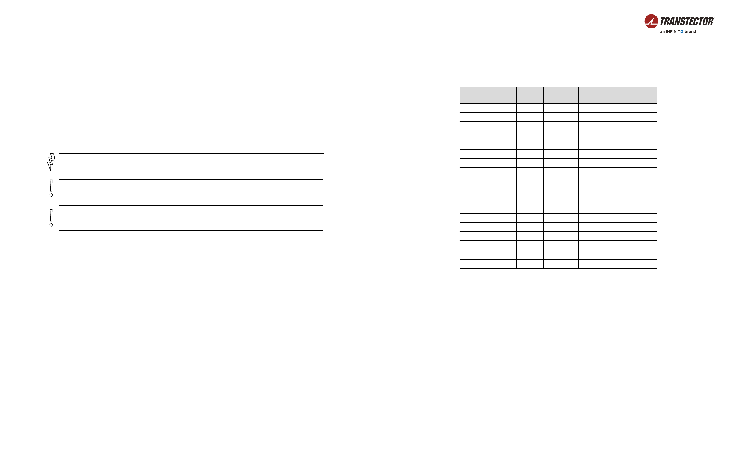
4.1.4 Cable Size
Please use the recommended cable size given below for the system installation.
Port Current
Max. Cable Size
Min.(mm²) Cable Size
Min.(AWG) Temperature
Rating
AC Input -L1 32A 10mm² 7 AWG 105°C
AC Input -L2 32A 10mm² 7 AWG 105°C
AC Input -L3 16A 10mm² 7 AWG 105°C
AC Input -N 32A 10mm² 7 AWG 105°C
AC Input -PE - 10mm² 7 AWG 105°C
Battery MCB 80A 20mm² 4 AWG 105°C
Battery MCB 100A 25mm² 3 AWG 105°C
Battery MCB 125A 35mm² 2 AWG 105°C
DC Load -MCB 63A 16mm² 5 AWG 105°C
DC Load -MCB 50A 14mm² 6 AWG 105°C
DC Load -MCB 40A 10mm² 7AWG 105°C
DC Load -MCB 32A 8mm² 8 AWG 105°C
DC Load -MCB 25A 8mm² 8 AWG 105°C
DC Load -MCB 20A 6mm² 9 AWG 105°C
DC Load -MCB 16A 4mm² 10 AWG 105°C
DC Load -MCB 10A 2.5mm² 14 AWG 105°C
DC Load -MCB 6A 2.5mm² 14 AWG 105°C
DC Load -MCB 4A 1.5mm² 15 AWG 105°C
Table 4-1 Recommended Electrical Cable Size
Circuit Breakers must not exceed the below loading based on maximum 55°C operating
ambient:
• For load breaker rated 5 to 32A, the maximum load must not exceed 80% of rating value.
• For load breaker rated up to 63A, the maximum load shall not exceed 40A if space is
provided between breakers. Maximum 30A is allowed if no space provided.
• For battery breaker rated up to 80A, the maximum load shall not exceed 80% of rating
value.
• For battery breaker rated 100 to 125A, the maximum load shall not exceed 75A.

Installation Manual | DCIPS2B-S-00-B11 Power Supply System
24 25
+1 (208) 635-6400 | www.transtector.com +1 (208) 635-6400 | www.transtector.com
4.2 Rack Mounting
There are two mounting brackets installed on the front left and right side of the power system
to enable you to securely fasten the sub-rack to a cabinet or an open frame.
NOTE For ease of mounting the power rack it is recommended to remove the rectiers.
NOTE When mounting the system to an open frame, the brackets should be moved to
the middle position.
To mount the subrack into a cabinet, follow the steps below:
1. Determine the installation position according to system measurement. Refer to the
Appendix A for details. Re-install the mounting bracket in another position if necessary.
Refer to the gure 4-1 below.
Two ways to install mounting
brackets in the front position
Figure 4-1 System Mounting - Cabinet
2. Place the system into the cabinet.
3. Fasten the system into the cabinet by using four M6 x 12mm screws and mounting
brackets on the front left and right side of the unit. Tighten the screws to 6 Nm.
To mount the system into an open frame, follow the steps below:
1. Determine the installation position according to system measurement. Refer to the
Appendix A for details.
2. Remove the mounting brackets on the front left and right side of the system.
3. Rex the mounting brackets to the middle left and right side of the system.
4. Place the system into the open frame.
5. Fasten the system to the open frame by using four M6 x 12mm screws and the mounting
brackets. Tighten the screws to 6 Nm.
Two ways to install mounting
brackets in the front position
Figure 4-2 System Mounting - Open frame / relay rack

Installation Manual | DCIPS2B-S-00-B11 Power Supply System
26 27
+1 (208) 635-6400 | www.transtector.com +1 (208) 635-6400 | www.transtector.com
4.3 Cable Entry
The plastic AC rear cover is the default conguration and should be removed for connecting
theAC cable. If the Rear and Top Cover Kit or Extended Rear and Top Cover Kit is installed,
the top cover and extended rear cover should be removed for connectingAC, DC and alarm
cables.
4.3.1 Remove Top Cover
If the Rear and Top Cover Kit is installed, follow the steps below to remove the top cover
and AC cover:
1. Remove plastic AC rear cover by loosing two screws.
2. Push the top cover backward and then lift it to remove the cover.
AC Cover
Top Cover
Figure 4-3 Remove Top Cover
If the Extended Rear and Top Cover Kit is installed, follow the steps below to remove the
extended rear cover and top cover:
1. RemovetheAC inputcoverassemblyandrearcoverassemblybylooseningtheretaining
screws.
2. Remove the support assembly of the Extended Cover Kit by unscrewing four screws
xed to power system.
3. Follow the steps of “Removing Top and AC Cover” to remove the plastic AC cover and
top cover.
Rear Cover Assembly
AC Input Cover
Assembly
Support Assembly
Figure 4-4 Remove Extended Cover Kit
4.3.2 Cable Entry Openings
The Extended Rear and Top Cover is designed with two knockouts and one circular opening
for AC cable entry plus and three larger openings for DC and alarm cable entry.
When connecting and routing the AC cable from the right hand side or the bottom, rst
remove the knockout, then install the supplied PG21 to x the AC cable.
Figure 4-5 below depicts three types of AC and DC cable entry.
AC cable entry from rear AC cable entry from bottomAC cable entry from side
DC cable entry from rear DC cable entry from bottomDC cable entry from rear
Figure 4-5 Cable Entry Options

Installation Manual | DCIPS2B-S-00-B11 Power Supply System
28 29
+1 (208) 635-6400 | www.transtector.com +1 (208) 635-6400 | www.transtector.com
4.4 Grounding Connection
Earth grounding connection is essential before connecting supply.
The positive DC busbar is connected to the grounding point in the rear of the system using
a copper bar. The grounding pole of the system is located in the rear right corner if no cover
installed.
1. Switch o all breakers on the distribution panel.
2. Connect an insulated cable with a cross-sectional area of 16mm² (5AWG) between the
earth connection point of the system and the Main Earth Terminal (MET).
3. Tighten the cable connection to a torque of 8 Nm.
Figure 4-6 Grounding Connection
If the Rear and Top Cover Kit is order and installed, the grounding pole on the rear cover is
suppled for convenient connection and cabling. Figure 4-7 below depicts how to connect
the earth grounding cable to the rear cover.
Figure 4-7 Grounding Connection with Rear & Top Cover Kit
Figure 4-8 Grounding Connection with Extended Rear Cover Kit - Two Point
Figure 4-9 Grounding Connection with Extended Rear Cover Kit - Single Point
4.5 AC Input Connection
WARNING Ensure that mains input is turned o before connecting. The grounding must
be connected to PE terminal as rst.
WARNING High leakage current. Ensure earth is connected before connecting mains
supply.
WARNING Only a qualied electrician may carry out the mains installation.
CAUTION Depending on deployment region with regards to lightning strikes and heavy
inductive energy, it is highly recommended to install AC Surge Protection Class C, if not
delivered with the system..

Installation Manual | DCIPS2B-S-00-B11 Power Supply System
30 31
+1 (208) 635-6400 | www.transtector.com +1 (208) 635-6400 | www.transtector.com
WARNING Used cable must be inserted into the terminal with as little insulation removed
as possible, so as to prevents any stranded conductor coming loose and touching any
other conductive parts. Tighten terminals securely with torque 1.5-1.8Nm.
1. Strip theAC input cable conductors to the correct length for connection to the terminals.
2. Route the AC input cable through the AC cable entry and connect the cable to the AC
terminals and tighten the screws to 1.5 - 1.8 Nm.
3. The mains input terminal blocks can be connected to:
• 1-phase 110VAC or 230VAC (Figure 4-10)
• 3-phase 110/190VAC or 230/400VAC (Figure 4-11).
LI L2 L3
NIN2 N3
PE
Figure 4-10 AC Cable Connection (1-phase)
Recommended mains breaker:
1-phase 110VAC or 1-phase230VAC: UL listed, Single pole 3 x 50AC-characteristics.
LI L2L3
NIN2N3
PE
Figure 4-11 AC Cable Connection (3W+N+PE)
Recommended mains breaker:
3-phase 230/400VAC: UL listed,Three pole 25AC-characteristics.
4. If the power system is to be connected to 208-240V North American 3-phase power
source, you have to rst connect terminal L1 with N3, L2 with N1 and L3 with N2
(3W+PE). Refer to Figure 4-12 for details.
LI L2L3
NIN2N3
PE
Figure 4-12 AC Cable Connection in North American (3W+PE)

Installation Manual | DCIPS2B-S-00-B11 Power Supply System
32 33
+1 (208) 635-6400 | www.transtector.com +1 (208) 635-6400 | www.transtector.com
4.6 DC Load Connection
Before connecting DC load cables, check that the cable rating is matched with selected the
MCB and/or load.
1. Check that all the load MCBs are in the OFF position.
2. Connect the negative (-) cable from the load to the relevant -48V bus bar at the rear of
the power rack. Use the M6 Hex screw and washer to x the load cable lug and tighten
to 8.0 Nm. The -48VDC bus bar has been connected to the relevant DC breakers.
Connect the positive (+) cable from the load to the relevant positive terminal on the bus
bar. Insert the stripped cable into the opening on top of the terminal and tighten the
screw to 3.0 Nm.
3. Connect the positive (+) cable from the load to the relevant positive terminal on the bus
bar. Use the M6 Hex screw and washer to x the cable lug and tighten to 8.0 Nm.
4. Check the load connection is right and load can be controlled by the corresponding load
breaker.
F6 F5 F4 FB2
F3 F2 F1 FB1
0V Return Bus
Figure 4-13 DC Load Connection
4.7 Battery Connection
The battery cables are not delivered with the system.
1. Check that all the battery MCBs are in the OFF position.
2. Connect the negative (-) cable of each battery string to the relevant -48V bus bar at
the rear of the power rack. Use the M8 Hex screw and washer to x the load cable lug
and tighten to 20 Nm. The -48VDC bus bar has been connected to the relevant battery
breakers (FB1, FB2). Refer to Appendix C for details.
3. Connect the positive (+) cable of each battery string to the relevant positive terminal on
the bus bar. Use the M8 Hex screw and washer to x the cable lug and tighten to 20 Nm.
4. Connect the other ends of the battery cables to the “-“and “+” terminals of the batteries.
Figure 4-14 Battery Connection

Installation Manual | DCIPS2B-S-00-B11 Power Supply System
34 35
+1 (208) 635-6400 | www.transtector.com +1 (208) 635-6400 | www.transtector.com
4.8 Alarm and Signal Connections
There are two kinds of alarm interface board for selection to meet the user’s requirement.
• ACX External Board: Select this if the ACX internal communication board is selected
and a maximum of 4 alarm relay outputs are required.
• ACX Relay Board: Select this if the ACX internal communication board is selected and
5 - 10 alarm relay outputs are required.
Figure 4-15 PCC External Board
XC3
3
2
1
Alarm 1 6
5
4
Alarm 2
XC6
3
2
1
Alarm 3
6
5
4
Alarm 4
XC5
2
1
Multi purpose 7-12
Multi purpose 1-6
XC2
+5V
0V
TEMP1(BATT)3
2
1
XC4
50 XC1
Digital In 2
+5V
Digital In 1 XC7
Digital out 2
+V
Digital out 1 XC8
+5V
0V
TEMP2(AMB) 6
5
4
4
3
6
5
8
7
10
9
12
11
GND
GND
Symmetry#1
Symmetry#2
Temperature
sensor
Red
Green
Blue
Red
Green
Blue
Red
Green
Blue
Temperature
sensor
Red
Green
Blue
Figure 4-16 ACX External Board
XC3
3
2
1
Alarm 1 6
5
4
Alarm 2
XC6
3
2
1
Alarm 3
6
5
4
Alarm 4
XC5
2
1
Multi purpose 7-12
Multi purpose 1-6
XC2
+5V
0V
TEMP1(BATT)3
2
1
XC4
50 XC1
Digital In 2
+5V
Digital In 1 XC7
Digital out 2
+VR
Digital out 1 XC8
+5V
0V
TEMP2(AMB) 6
5
4
4
3
6
5
8
7
10
9
12
11
1
2
3
4
5
6
1
2
3
4
5
6
1
2
3
4
5
6
K1
K2
K4
K3
K5
K6
XC10
XC9
XC11
GND
GND
Symmetry#1
Symmetry#2
Temperature
sensor
Red
Green
Blue
Red
Green
Blue
Red
Green
Blue
8
8XC13
XC12
Temperature
sensor
Red
Green
Blue
Figure 4-17 ACX Relay Board
The alarm interface board is located in the top right side of the system. To connect the alarm
cable to the alarm interface board, follow the steps below:
1. Pull out the alarm interface board support by unscrewing two retaining screws on the
rear of the power system (Figure 4-18, #1).
2. Remove the green plug from each connector (Figure 4-18, #2)
3. Determine whether to reference normally closed or normally open with reference to
common for each alarm contact.
4. Strip the wires back approximately 10mm. Stranded wire may be soldered or covered
with copper ferrule if desired.
5. Insert the wire into the openings of green plug and tighten screw to clamp wire (Figure
4-18, #3).
6. Re-insert the the green plug with the alarm cable into the alarm interface board (Figure
4-18, #4).
7. Replace the alarm interface board support and x it.

Installation Manual | DCIPS2B-S-00-B11 Power Supply System
36 37
+1 (208) 635-6400 | www.transtector.com +1 (208) 635-6400 | www.transtector.com
44
Figure 4-18 Alarm Connection
NOTE The alarm conguration will be dependent on your system conguration.
NEED MORE INFORMATION? For detailed information regarding Alarm connection see
Appendix A, Installation Drawing.
4.9 Symmetry Connection
The ACX controller can supervise 4-block symmetry measurements on 4 battery branches.
NOTE Symmetry cables are pre-connected to the system.
NOTE Multi Purpose inputs which are not used for symmetry measurement can be
recongured to user dened analog inputs.
1. Insert a suitably sized cable lug into one pole of the inter-block connection plate. Fasten
the lugs and plates to individual battery poles.
2. For 2-block battery symmetry measurement x one wire of the symmetry cable to the
cable lug in the mid-point of the battery string, see Figure 4-19.
Figure 4-19 2-block Symmetry Measurement (for illustration only)
For 4-block measurement x the 3 wires (red, green and blue) of the symmetry cable to
individual cable lugs. Color coding of the cables must be followed for proper symmetry
measurement, see Figure 4-20.
Figure 4-20 4-Block Symmetry Measurement (for illustration only)
NOTE The interblock Connection Kit is not delivered with the system.
4.10 Temperature Sensor Connection
NOTE The power system is usually delivered with pre-connected temperature
sensor cables. If not, use a three-pin plug and connect according to the Appendix A -
Installation Details.
Battery Temperature
Temperature sensor 1 measures the temperature of the battery bank while the controller
adjusts the oat charge voltage according to the temperature compensation factor set in the
controller. This factor must be set in the controller according to the battery manufacturer ‘s
recommendations.

Installation Manual | DCIPS2B-S-00-B11 Power Supply System
38 39
+1 (208) 635-6400 | www.transtector.com +1 (208) 635-6400 | www.transtector.com
Fasten the temperature sensor in the middle of the battery bank, Figure 4-21.
Temp. Sensor
Figure 4-21 Temperature Sensor Connection
NOTE The temperature compensation factor can be set only for temperature sensor 1.
Ambient Temperature
Temperature sensor 2 allows a second temperature reading, most commonly the ambient
temperature around the system. Place the sensor as required.
The temperature is displayed in the External Measurements menu in the ACX controller or
in PowCom™ software.
NOTE Temperature sensor 2 can be activated only in the systems with the ACX
controller installed.
4.11 Connecting an RS232 Communication Cable
The controller can communicate with an external device such as a network interface card
through an RS232 connection.
1. Remove the top cover of the controller.
2. Connect the RJ45 port of the RS232 communication cable to the RJ45 port marked with
RS232 on the internal communication board.
3. Pull out and x the DB-9 connector of the RS232 communication cable for application.
4. Re-install the top cover of controller.
Figure 4-22 RS232 Connection
4.12 Rectier Installation
NOTE Ensure that the rectier handle is in the OPEN position (forms 35-40° angle with
rectier body) before inserting the module into the slot.
Rectier module should be installed starting from the bottom left position in the rectier shelf.
1. Place the rectier module in the mounting slot with handle facing out.
2. Slide the rectier module into the slot until it contacts the interface connection at the rear
of the shelf, Figure 4-23 #1.
3. Fully insert the rectier by pushing the handle towards the shelf. The rectier handle will
rise up and lock the rectier into the position, Figure 4-23 #2.
4. Repeat steps 1 to 3 if more rectiers are to be installed.
2
1
Figure 4-23 Rectier Installation
Table of contents
Other Infinite Power Supply manuals


