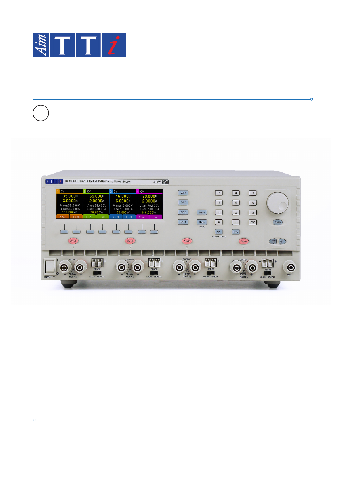
1 - Product Description
1 MX-Q & MX-QP Series 2 Instruction Manual
Product Description...................................................................................................................... 4
Power Capability...........................................................................................................................................................4
Available Ranges...........................................................................................................................................................4
Safety............................................................................................................................................. 5
Symbols.........................................................................................................................................................................5
Safety Notices...............................................................................................................................................................6
Installation..................................................................................................................................... 7
Mains Operating Voltage .............................................................................................................................................7
Mains Lead ...................................................................................................................................................................7
Mounting......................................................................................................................................................................7
Ventilation ....................................................................................................................................................................7
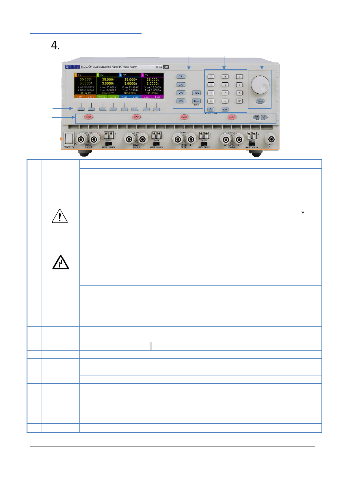
Instrument Overview..................................................................................................................... 8
Getting Started .............................................................................................................................10
Using this manual.......................................................................................................................................................10
Switching on ...............................................................................................................................................................10
Display.........................................................................................................................................................................11
Initial operation..........................................................................................................................................................12
Setting with Individual Output Screens.....................................................................................................................13
Setting Over-Voltage and Over-Current protection..................................................................................................14
Setting the Voltage/Current Range ...........................................................................................................................15
Store and Recall of Settings.......................................................................................................................................16
The System Menu Screen ..........................................................................................................................................16
Voltage Tracking .........................................................................................................................................................16
OVP /OCP TripLink ......................................................................................................................................................17
Display Symbols..........................................................................................................................................................17
Menu - Advanced Functions........................................................................................................18
Menu...........................................................................................................................................................................18
Setting Voltage Tracking.............................................................................................................................................18
Current Meter Averaging Setup ................................................................................................................................19