INFINITI FITNESS PG750 Quick reference guide
1
Assembly & Operating Instructions
PG750 Magnetic Bike
®

1
EXPLORATION DRAWING

1
DRAWING FOR ASSEMBLY

2
PARTS LIST AND TOOLS
No. Description Q'ty
A Computer 1PCS
A-1 Screw 4PCS
B Handlebar assembly 1SET
B-1 End cap 2PCS
B-2 Pulse sensor 2PCS
B-3 Screw 2PCS
B-4 Pulse cable 1PCS
B-5 Foma grip 1PCS
B-6 End cap for pulse cable 1PCS
C Computer post 1SET
C-1 Computer cable 1PCS
C-2 Screw 2PCS
D Mainframe 1SET
D-1 Flat washer 4PCS
D-3 Screw 4PCS
D-4 Computer cable, lower section 1PCS
D-5 Bearing 2PCS
D-6 Screw for RPM sensor 1PCS
D-7 RPM sensor 1SET
D-8 Flat washer 1PCS
D-9 C clip 1PCS
D-10 Right chain cover fornt 1PCS
D-11 Right chain cover 1PCS
D-12 Screw 10PCS
D-13 Crank cap 2PCS
D-14 Right Crank 1PCS
D-15 Right pedal 1PCS
D-16 Left pedal 1PCS
D-17 Lock-tie bolt 2PCS
D-18 Left crank 1PCS
D-19 Screw 5PCS
D-20 Left chain cover fornt 1PCS
D-21 Screw 6PCS
D-22 Left chain cover 1PCS
D-23 Wave washer 1PCS
D-24 Flat washer 10PCS
D-25 Adaptor 1PCS

3
No. Description Q'ty
D-26 DC socket with cable 1PCS
D-27 Idler spring 1PCS
D-28 Bottle holder 1PCS
D-29 Ring 2PCS
E Flywheel assembly 1SET
E-1 Nut 5PCS
E-2 Star washer 2PCS
E-3 Bearing 1PCS
E-4 Flat washer 1PCS
E-5 Bearing 1PCS
E-6 One-Way bearing set 1PCS
E-7 Flywheel 1PCS
E-8 Flywheel axle 1PCS
E-9 Bearing 1PCS
E-10 Small pully 1PCS
E-11 Bearing 1PCS
F Idler assembly 1SET
F-1 Wave washer 2PCS
F-2 Idler roller 1PCS
F-3 Hex bolt 1PCS
F-4 Flat washer 1PCS
F-5 Flat washer 1PCS
F-6 Nylon nut 1PCS
F-7 Flat washer 1PCS
F-8 Hex bolt 1PCS
G Shaft assembly
G-1 Bushing 1PCS
G-2 Drive pully 1PCS
G-3 Shaft 1PCS
G-4 Hex bolt 3PCS
G-5 Belt 1PCS
H Front stabilizer 1PCS
H-1 Leveling foot 4PCS
H-2 Foot stopper 4PCS
H-3 Foot 4PCS
H-4 Screw 2PCS
H-5 Roller 2PCS
H-6 Flat washer 2PCS
H-7 Nylon nut 2PCS

4
No. Description Q'ty
I Rear stabilizer assembly 1PCS
I-1 Rear stabilizer 1PCS
J Seat post assembly 1PCS
J-1 Sleeve 1PCS
J-2 Knob for seat post 1PCS
J-3 Screw 4PCS
J-4 Seat slider cap, Left 1PCS
J-5 Seat slider cap, Right 1PCS
J-6 Seat knob 1PCS
J-7 Flat washer 1PCS
J-8 Screw set 1PCS
J-9 End cap 2PCS
J-10 Seat post 1PCS
J-11 Saddle 1PCS
K-1 Handlebar clamp 1PCS
K-2 Handlebar clamp cover 1PCS
K-3 Flat washer 2PCS
K-4 Lock washer 2PCS
K-5 Screw 1PCS
K-6 T knob for handlebar 1PCS
K-7 Bushing 1PCS
K-8 Screw 8PCS
L Gear motor 1SET
L-1 Bolt 1PCS
L-2 Flat washer 2PCS
L-3 Hex bolt 2PCS
L-4 Lock washer 2PCS
L-5 Flat washer 2PCS
L-6 Bushing 2PCS
L-7 I-bolt 1PCS
L-8 Hex nut 2PCS
L-9 C clip 2PCS
L-10
Wave washer
1PCS

5
ASSEMBLY INSTRUCTIONS
Stage#1
8*
STEP 1
STEP 2
1. Put on front stabilizer (H) and rear stabilizer (I) to the mainframe assembly.
Be noted: the front stabilizer has transportation wheel. Use Screw (K-8)
to fix the stabilizers tightly.
2. Fix the right pedal (D-15) and left pedal (D-16) tightly to the right/left crank.

6
Stage#2
4*
STEP 3
1. Connect the upper and lower table together.
2. Fix the handlebar post to the main frame with Screws (D-3) and washer (D-1).

7
Stage#3
1*
1*
1*
1*
2*
2*
STEP 4
1. Assemble the handlebar (B) to the bracket on the handlebar post with handlebar clamp
(K-1), Cover for metal cover (K-2) flat washer (K-3), washer (K-4) and screw (K-5). Bushing
(K-7)
2. Fix the T-knob (K-6) to the plastic cover. Adjust the handlebar with your desired angle.
Fasten the T-knob. Tight the bottle holder (D-28) to the handlebar post with two screws
(C-2).
8
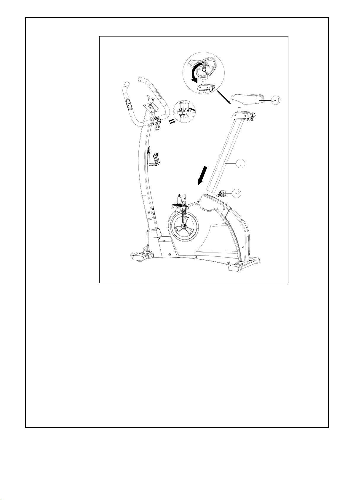
Stage#4
STEP 5
Fasten the saddle (J-11) to the seat post (J).
And fix the seat post to the main frame with seat
knob (J-2).

9
Stage#5
STEP 6
1. Connect the pulse cable coming out of the handlebar and the computer cable to
the computer (A). Place the computer to the computer mast and fasten with Screws
(A-1). Then the assembly is done.

10
Hardware Kit
NNNNNNNNNNNNNNNNNNNNNNNNNNNNN
NNNNNNNNNNNNNNNNNNNNNNNNNNNNNNNNNN
(MM)
NNNNN NTNNNNpNNknob
NMNN 5LNNNNN
NN5NANNNnNBoNNN
MNNPNN0NN0MMNNNN
NNNNNNNSpNinNN
NNNNNNNNNNN ScNNwNNiNNNNNNNN
BoxNSpNnnNNNNNNN
NNNNNNNBNNNinN
NNNNNN0MMNNNN
NNNNNNNMNNNNNcoNNNNNNN
ANNNnNNNyNNNN

11
INSTRUCTION MANUAL OF SM2703
BUTTON FUNCTION:
MODE/ENTER
In stop mode, the mode is to confirm all exercise data setting, and enter into program.
RESET
In stop mode, press the button back to main menu.
START/STOP
To start or stop exercise.
RECOVERY
To test hear rate recovery status.
UP
To select training mode and adjust function value up.
DOWN
To select training mode and adjust function value down.
TOTAL RESET
To power on the computer again.
DISPLAY EXERCISE DATA:
TIME Display range 0:00~99:99 ; Setting range 0:00~99:00
DISTANCE Display range 0.00~99.99 ; Setting range 0.00~99.90km
CALORIES Display range 0~9999 ; Setting range 0~9990
PULSE Display range P-30~230 ; Setting range 0-30~230
WATT Display range 0~999 ; Setting range 10~350
SPEED 0.0~99.9km
RPM 0~999
OPERATION PROCEDURE
1. Connect power supply and computer will power on with a long beep sound, LCD display all segments
(drawing A) for 2 seconds and enter into personal data setting mode (gender, age, height and weight) for
U1 U4. (drawing B C)
2. After user data set up, computer will display main menu (drawing D).
A B
C D
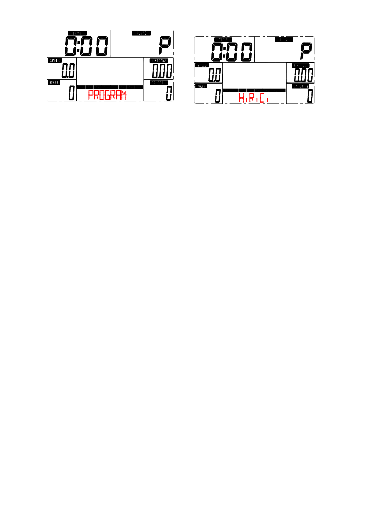
3. In main menu, first exercise program MANUAL will flash, user may press UP and DOWN button to
select MANUAL PROGRAM (12 profiles) (drawing E)PROGRAMUSER
12
PROGRAMHRCWATT.
圖5 圖6
4. Quick Start and Manual :
Before exercise in Manual mode, user my set up TIME, DISTANCE, CALORIES and PULSE
target.
After power on, user may press START/STOP button to start exercise in MANUAL immediately
without any setting.
Level can be adjusted during exercise by press UP or DOWN.
5. PROGRAM:
Before exercise in Program mode, user may set up TIME target.
Press UP and DOWN to select Program with 12 profiles and press ENTER/MODE to confirm.
Level can be adjusted during exercise by press UP or DOWN.
6. H.R.C.:
Before exercise, computer will ask for user AGE first to calculate TARGET pulse. User may still
press UP and DOWN to change target pulse from 30 to 230.
7. USER PROGRAM:
User may press UP, DOWN and then press MODE to create his own profile. (from column 1 to
column 20) User may hold on pressing MODE button for 2 seconds to quit profile setting.
8. WATT :
The preset watt value 120 is flashing on screen in WATT setting mode. User may use UP, DOWN
button to set target value from 10 to 350. Press MODE button for confirm.
9. RECOVERY :
After exercising for a period of time, keep holding on handgrips and press “RECOVERY”
button. All function display will stop except “TIME” starts counting down from 00:60 to 00:00.
Screen will display your heart rate recovery status with the F1,F2….to F6. F1 is the best, F6
F6 is the worst. User may keep exercising to improve the heart rate recovery status.
(Press the RECOVERY button again to return the main display.)
NOTE:
1. This computer require 9V, 500mA adaptor.
2. When user stop pedaling for 4 minutes, computer will enter into power save mode, all setting and
exercise data will stored until user start exercise again.
3. When computer act abnormal, please plug out the adaptor and plug in again.
Table of contents
Other INFINITI FITNESS Exercise Bike manuals


