manuals.online logo
Brands
  1. Home
  2. •
  3. Brands
  4. •
  5. Infinity
  6. •
  7. Amplifier
  8. •
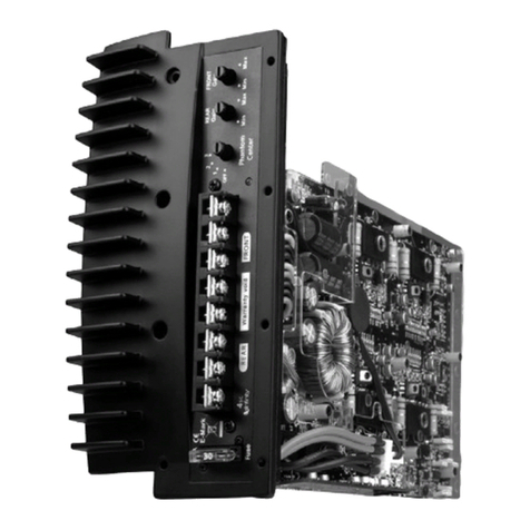
  9. Infinity KAPPA FIVE User manual

Infinity KAPPA FIVE User manual

Kappa Five
5 CHANNEL POWER AMPLIFIER
SERVICE MANUAL
Infinity Systems Incorporated
250 Crossways Park Dr.
Woodbury, New York 11797
Rev16/2010
Released 2009
Discontinued XXXX
- CONTENTS -
SPECIFICATIONS ………………………………………..1
PACKAGING………..………………………………..…....2
CONTROL/INSTALLATION INSTRUCTIONS….……....3
CONTROL/INSTALLATION DRAWINGS……….………4
BASIC TROUBLESHOOTING……………………………5
EXPLODED VIEW/PARTS LIST…….….….…………....6
DISASSEMBLY INSTRUCTIONS………………………..7
AMPLIFIER BLOCK DIAGRAM…………………….……8
ELECTRICAL PARTS LIST ..……….……….…….…….9
P.C.B. DRAWINGS….………………………..…….……15
IC/TRANSISTOR PINOUTS..………………..….….…..29
SCHEMATICS……………..……………….………..…...37
Kappa Five Specifications
Output Power: 50W RMS x 4 channels @ 4 ohms ≤1% THD + N
(14.4V supply) & 200W RMS x 1 channel @ 4 ohms; ≤1% THD + N
75W RMS x 4 channels @ 2 ohms; ≤1% THD + N
& 300W RMS x 1 channel @ 2 ohms; ≤1% THD + N
Bridged (3 channel) 150W RMS x 2 & 200W RMS x 1 @ 4 ohms ≤1% THD + N
Total Peak Power 1200W
Signal-to-noise ratio: 85dBA (reference 1W into 4 ohms)
100dBA (reference rated power into 4 ohms)
Frequency response: 10Hz – 75kHz & 20Hz – 320Hz (–3dB)
THD+N 1KHz LPF=22KHz ≤0.05% (rated power @ 4 ohms)
Output Regulation 0.03dB @ 4 ohms
Input Impedance >20K ohms
Maximum input signal: 6.0V
Maximum sensitivity: 200mV
Bass Boost @ 50Hz 0-12dB
Channel Separation ≥50dB
DC Offset <30mV
Idle Current @ 4 ohms 2.0A
Max Current Draw ≤80A
Remote Operating Voltages ON 5V OFF 4V
Turn On Delay Time (sec) 2 - 3
Circuit Protection Temperature (75C), Short circuit, over/under voltage
Operating voltage range (8-16V)
Dimensions: 14 x 7 x 1.7” (360 x 179 x 44mm)
Fuses: (2) x 40A
Infinity Systems continually strives to update and improve existing products, as well as create new ones. The
specifications and details in this and related JBL publications are therefore subject to change without notice.
1
KAPPAFIVE
2
KAPPAFIVE
Installation Warnings and Tips:
• Disconnect the negative (–) lead from your vehicle’s
battery.
• At the installation sites, locate and make a note of all
fuel lines, hydraulic brake lines,vacuum lines and
electrical wiring. Use extreme caution when cutting
or drilling in and around these areas.
• Choose a safe mounting location away from moisture.
• Make sure there is sufficient air circulation at the
mounting location for the amplifier to cool itself.
• Mount the amplifier, using the supplied hardware.
Specifications
• 50W RMS x 4 channels & 200W RMS x 1 channels
@ 4 ohms <1% THD + N*
• 75W RMS x 4 channels & 300W RMS x 1 channels
@ 2 ohms <1% THD + N*
• Total peak power: 1200W
• Frequency response: 10 to 75kHz & 20 to 320Hz (–3dB)
• Maximum input signal: 6V*
• Maximum sensitivity: 200mV*
• THD + N: 0.05%
• Signal-to-noise ratio: 85dBA (reference to 1 watt)
• Signal-to-noise ratio: 100dBA (reference to rated power)
*CEA-2006A-compliant
0Speaker Output Connectors
• Connect the speakers to these terminals, observing
proper polarity. Gold screws indicate +,and silver
screws indicate – .
• Five-channel operation: Connect the front left
speaker to the Front L+ and L– terminals and
the front right speaker to the Front R+ and R–
terminals.Repeat for the rear speakers, using
the Rear L+ and L– terminals,and the Rear R+
and R– terminals.Connect the subwoofer to the
Sub+ and Sub– terminals.
• Four-channel operation: Connect the stereo speakers
to the Front terminals, as above.The single speaker,
into which the amplifier’s rear channels will be
bridged, must be connected to the Rear terminals
marked “B.” Connect the subwoofer to the Sub+ and
Sub– terminals.
• Three-channel (bridged) operation: Connect one
speaker to the Front terminals marked“B.” Connect
the other speaker to the Rear terminals marked “B.”
Connect the subwoofer to the Sub+ and Sub–
terminals.
• Minimum speaker impedance for stereo operation is
2 ohms. Minimum speaker impedance for bridged
operation is 4 ohms. Minimum subwoofer impedance
is 2 ohms.
1Fuses
• Replace only with the same type and rating.
2Power Input Connectors
• +12V: Connect to the positive terminal of the vehicle’s
battery. 4 AWG wire is recommended. Install an
appropriate fuse holder and fuse (80A minimum) within
18' of the battery. Make sure the wire is not damaged
or pinched during installation. Install protective
grommets when routing wires through the firewall
or other sheet metal.
• GND: Connect to the vehicle’s chassis. Refer to
the illustration below.
4 AWG Adapter
• For power wire longer than 4' (1.2m), 4 AWG wire is
recommended. Use the adapter to make the connection
according to the illustration below.
3Protect LED
• Illuminated under any of the following fault
conditions: battery over/under voltage, short
circuit in speaker wires,amplifier is too hot,
amplifier’s output circuit has failed (DC voltage
present in the amplifier’s output).
4Power On LEDs
• Illuminated when the amplifier is on.
5Subwoofer Low-Pass Filter
Frequency Control
• 12dB/Octave low-pass filter, variable from
32Hz to 320Hz.
• See Jfor the adjustment procedure.
6Subwoofer Input-Level Control
• Used to match the SUB input of the amplifier to the
output of the source unit.
• See Jfor the adjustment procedure.
7Rear Input-Level Control
• Used to match the rear input level of the
amplifier to the output level of the source unit.
• See Jfor the adjustment procedure.
8Front Input-Level Control
• Used to match the input level of the amplifier to
the output level of the source unit. See Jfor the
adjustment procedure.
9Front Crossover-Frequency Control
• 12dB/Octave crossover, variable from 32Hz to 320Hz.
ARear Crossover-Frequency Control
• 12dB/Octave crossover, variable from 32Hz to 320Hz.
See Jfor the adjustment procedure.
BDBO: Variable Subsonic High-Pass
Filter With Variable Boost (Q)
• For woofers in tuned (vented) enclosures, set
the frequency control to a value 10Hz below the
enclosure’s resonance (tuned) frequency.
• For woofers in sealed boxes, set the frequency control
to any value you prefer between 30Hz and 50Hz.
• Set the Boost control according to your preference,
being careful not to apply enough boost to damage
your woofer(s).
ABoost (Q) control provides up to 12dB of boost,
slightly above the high-pass filter’s frequency.
See Bfor appropriate settings.
BHigh-Pass Filter Frequency control, variable
between 10Hz and 80Hz.See Bfor appropriate
settings.
CRear Crossover-Filter Selector
• LP: Select for subwoofer(s) or to provide a low-pass
filter for separate mid-bass speakers.The subsonic
filter will provide a high-pass filter for separate
mid-bass speakers.
• FLAT: Select for full-range speakers when
no subwoofer will be used in the system.
• HP: Select for midrange speakers or full-range
speakers when a subwoofer is used in the system.
DFront Crossover-Filter Selector
• LP: Select for subwoofer(s).
• FLAT: Select for full-range speakers when no
subwoofer will be used in the system.
• HP: Select for midrange speakers or full-range
speakers when a subwoofer is used in the system.
EInput Selection Switch
• If you are using RCA-type inputs and the source unit
has a subwoofer output, and you have connected it to
the SUB input, set this switch to the EXT position.
Otherwise, set it in the INT position.
FSubwoofer Input Connector (RCA)
• Connect to subwoofer RCA-type outputs from the
source unit or signal processor.
GRear Input Connectors (RCA)
• Connect to rear RCA outputs from the source unit,
or signal processor.
HFront Input Connectors (RCA)
• Connect to front RCA outputs from the source unit
or signal processor.
IRear Input Signal Selection Switch
• If your source unit has only front RCA-type outputs
and they are connected to the amplifier’s Front input
connectors, move this switch to the FRONT setting.
If your source unit has 4 RCA-type outputs, leave it
in the 4CH position.
JSetting Gain (Input Level)
ATurn all Gain controls counterclockwise to
6V (minimum).
BWith a dynamic music track playing, turn the head
unit’s volume control to the 3/4 position.
CTurn Front Gain control clockwise until the music is
so loud that it no longer sounds clear (distortion is
present in the output).
DTurn Front Gain control counterclockwise gradually,
just until the music sounds clear, once again.
EFront Gain is now adjusted correctly.
FAdjust Rear- and Sub-Gain controls so that the level
of the rear speakers is proportionate to the level of
the front speakers, according to your preference.
KSetting the Crossover
ACrossover setting for 5" or larger full-range speakers
when no subwoofer is included in the system.
BCrossover setting for full-range speakers when
a subwoofer is included in the system.
CCrossover setting for subwoofers.
Note: Acceptable frequency ranges indicated in gray.
Factory Bolt Ring Connector
Ground Wire
Note: Remove any paint
below ring connector.
Star Washer
This product is designed for mobile applications and is not intended
for connection to the mains.
A valid serial number is required for warranty coverage.
Features, specifications and appearance are subject to change
without notice.
3a
3
KAPPAFIVE
¡
1
2
B
5
6
7
8
EIF G H
123456qw890QWERT
TYUIOOPLKJHGFDSA
ZXCVBBEILKJ
HGFDACVBNM!!!!
!!!!7890
A
B
L
BB
BB
F
R
O
N
T
R
E
A
R
RRSUBL
34
9 A
C
D
K
ABC
ABCDEF
J
3x
4x 1x
1x
3a
4
KAPPAFIVE
Amplifier Troubleshooting Guide
1. Status LED on Amplifier not Lit - Head Unit (Source) Turned ON
Verify: A. Remote turn-on wire from source to amplifier has proper voltage
B. Power (B+) connections at amplifier, terminal blocks, and battery are secure
C. Ground (GND) connections at amplifier and vehicle chassis are secure
D. Battery B+ fuse (if used) is OK
E. Amplifier fuse is OK
F. B+ at battery and B+ at amplifier has proper voltage
2. Status LED’s Lit, No Output from Speakers in Normal Operating Condition
Verify: A. RCA cables from amplifier to source are securely connected
B. Volume adjustment on amplifier is correctly adjusted
C. Source is ON and playing
3. Engine Noise From Speaker(s)
Turn source OFF, Disconnect RCA cables at amplifier. If noise stops, check equipment & cables leading
to amplifier.
Verify: A. RCA cables are of good quality with no breakage to internal shields
B. RCA cables from source to amplifier are not run alongside any power cables
4. Amplifier Output Distorted Music
Verify: A. Source output music to amplifier is not distorted
B. Source output sensitivity is correctly adjusted
5. Amplifier Shuts Down, Green LED’s are Lit - Amplifier is in Thermal Protection Mode
Verify: A. Amplifier is mounted with adequate air circulation around heatsinks or vents
B. Amplifier is not mounted under carpet or sealed enclosure
C. Speakers meet correct impedance for application (mono or stereo hookup)
6. Amplifier Does Not Turn ON, and Red LED is Lit Amplifier (and not Connected to a Shorted Speaker)
Verify: A. Speaker crossover (if used) is not defective
5
KAPPAFIVE
6
KAPPAFIVE
KAPPA FIVE DISASSEMBLY INSTRUCTIONS
NOTE keep track and separate any and all screws; they are dissimilar.
For examination:
1) Remove the two screws at opposite ends on the bottom of the heatsink.
2) Remove the end panel on the Input side only, four Phillips screws.
3) Slide both pieces of silver trim off the heatsink.
4) Remove the top cover; it will be attached with a cable so unplug the connector.
For most component repairs on the MAIN PCB, the entire PCB must be removed from the heatsink.
Note the 4 channel output MOSFETS (IRF6645) are an exception; skip to steps 1-5 below.
5) Remove the Output end panel, five Phillips screws.
6) Remove the terminal screws to the Power connections, and top row only of the speaker
terminals.
7) Remove the remaining four Phillips screws on the bottom of the heatsink. There are two nuts
which may spin on the machine screws; look at the top of the PCB.
8) Remove all Phillips screws holding the Aluminum transistor clamps on; remove the clamps.
Two screws holding two additional TO-220 devices should be removed.
9) Remove the Amplifier PCB; six Philips screws. The PCB will then pull straight up and off the
MAIN PCB.
10) Slide the complete PCB out of the heatsink channel.
Access to the (8) output MOSFETS Q3A, Q4A, Q5A, Q6A, Q2, Q8, Q13, Q14
1) Follow steps #1-4 above.
2) Remove the two centermost screws on the bottom of the heatsink.
3) Follow step #9 above to remove the Amplifier PCB
4) Remove the gray heatsink from the PCB by grasping and pulling it straight out – it is only held on by
friction from the white heatsink compound.
5) The (8) output MOSFETS are underneath the rectangular insulator on the PCB.
7
KAPPAFIVE
1
1
2
2
3
3
4
4
5
5
6
6
D D
C C
B B
A A
1 2
L1
LPF
1
23
G
S
D
1
23
G
S
D
+VCC
-VCC
IRS20955S
Gate Driver
Daughter-Board
PWM
Modulator
and Level
shltter
Integrator
2
1
4
3
A
32Hz 80Hz 320 Hz
32Hz 320 Hz
10Hz 60k Hz
60KHz
3
21
A5
67
84
B
1 3
2
2
14710
rca inA
1
2
3
4
5
6
INS in
A
1 2
LPF
1
23
G
S
D
1
23
G
S
D
+VCC
-VCC
IR2010
Gate Driver
Daughter-Board
PWM
Modulator
and Level
shltter
Integrator
1 2
32Hz 80Hz 320 Hz
3
21
OP-2P
A
5
67
84
OP-2P
B
2
14710
rca inA
1 3
2
25Hz
320 Hz
180 Hz +1 2dB
BASS BOOST
LP FREQ
LOP PASS
HPPASS
FULL
3
21
OP-2P
A
2
14710
RCA-8CH
A
FL/FR/RL/RR
SUB
DWG NO:
PAR T NO:
PAR T NAME:
PRODUCT MODE:
SCALE:
UNIT: MM
SIZE: A2
REV:
DRAWBY:
CHECKED BY:
APPROVED BY:
DATA:
DATA:
DATA:
Kappa Five
HuiLian Li
方框图
8
KAPPAFIVE
KAPPA FIVE Electrical Parts List
Part Number Qty Reference Designator
Main PCB
Resistors
0702-0106-03 Resistor 10 1.5 10.5MM H16.5MM 1 R123P
0703-2000-01 Resistor 1/4W 0Ω±1% 3 J23 J2 J18
0704-4220-02 Resistor 1W 22Ω±5% 3 RR1 R180P R183P
07031185XK03 Resistor 1/8W 1.85K ±1% 1 R153PP
0704-64R7-02 Resistor 2W 4.7Ω±5% 3 R125E R126 R153P
0704-6222-02 Resistor 2W 2.2K ±5% 2 R118E R119E
0706-A160-02 Resistor 10W 16Ω±5% 23*13*13MM 1 R1A
0701-2000-02 Resistor SMD 0Ω1/8W ±5% 0805 9 R132A R132B R132C R132D L21 L22 L25 L26
L28
0701-2100-02 Resistor SMD 10Ω1/8W ±5% 0805 1 RR
0701-A220-02 Resistor SMD 22Ω1W ±5% 2512 7 RR2 RR3 RR4 R126P R126PB R110PB R110P
0701-2220-02 Resistor SMD 22Ω1/8W ±5% 0805 6 R130G R128E R129E R130E R129G R127E
0701-2101-02 Resistor SMD 100Ω1/8W ±5% 0805 8 R170P R171P R172P R173P R174P R175P
R176P R177P
0701-2221-02 Resistor SMD 220Ω1/8W ±5% 0805 3 R121 R53 R158PP
0701-2102-02 Resistor SMD 1KΩ1/8W ±5% 0805 20
R115E R411 R111A RA105P RA104P R104P
R105P R111C R111B R111D R126B R120 R104D
R104A R113 R104B R213 R413 R104C R313
0701-2222-02 Resistor SMD 2.2KΩ1/8W ±5% 0805 4 R58 R116E R117E R121S
0701-2272-02 Resistor SMD 2.7KΩ1/8W ±5% 0805 3 R52 R111P R123S
0701-2332-02 Resistor SMD 3.3KΩ1/8W ±5% 0805 2 R7 R8
0701-2392-02 Resistor SMD 3.9KΩ±5% R0805 3 R218E R219E RA33
0701-2472-02 Resistor SMD 4.7KΩ1/8W ±5% 0805 1 R3
0701-2512-02 Resistor SMD 5.1KΩ1/8W ±5% 0805 1 R151G
0701-2562-02 Resistor SMD 5.6KΩ1/8W ±5% 0805 2 R507G R502G
0701-2682-02 Resistor SMD 6.8KΩ1/8W ±5% 0805 6 R105E R129A R129B R129C R129D R158P
0701-2103-02 Resistor SMD 10KΩ1/8W ±5% 0805 30
R705 R706 R707 R708 R52A R105A R105B
R105C R105D R107A R107B R107C R107D R114
R123G R124F R125A R125B R125C R125D
R126C R128G R131E R138E R158PA R187P
R188P R311 R412 R501G
0701-2133-02 Resistor SMD 1/8W 13KΩ±5% 0805 1 R314
0701-2153-02 Resistor SMD 15KΩ1/8W ±5% 0805 5 R51 R158PD R161PA R508G RA279E
0701215K8002 Resistor SMD 15.8K 1/8W ±1% 0805 1 R126D
0701-2203-04 Resistor SMD 20KΩ1/8W ±5% 0805 3 RA34 R312 R123F
0701-2223-02 Resistor SMD 22KΩ1/8W ±5% 0805 20
R108 R208 R308 R408 R701 R101 R103E R110B
R114A R114B R114C R114D R127G R139E R201
R301 R315 R401 R501 R601
0701-2303-02 Resistor SMD 30KΩ1/8W ±5% 0805 2 R126A R126G
0701-2393-02 Resistor SMD 39KΩ±5% 0805 3 R507 R607 RA278
0701-2433-02 Resistor SMD 43K 1/8W ±5% 0805 1 R137E
0701-2473-02 Resistor SMD 47KΩ1/8W ±5% 0805 35
R102 R103 R105 R106 R110A R110C R110D
R133A R133C R134A R134C R202 R203 R205
R206 R302 R303 R305 R306 R402 R403 R405
R406 R502 R503 R505 R506 R509S R602 R603
R605 R606 R709S R809S R609S
0701-2563-02 Resistor SMD 56KΩ1/8W ±5% 0805 13 R109 R110 R209 R210 R309 R310 R409 R410
R160P R161P R162P R163P R164PP
0701-2623-02 Resistor SMD 62KΩ1/8W ±5% 0805 2 R205E R207E
0701-2823-04 Resistor SMD 82KΩ1/8W ±1% 0805 1 RA179E
0701-A472-02 Resistor SMD 4.7KΩ1W ±5% 2512 4 R4 R5 R6 R9
0701-2273-02 Resistor SMD 27KΩ1/8W ±5% 0805 3 R136E R702 R703
0701-A221-02 Resistor SMD 220Ω1W ±5% 2512 1 R132E
0701-A103-02 Resistor SMD 10K 1W ±5% 2512 1 R149P
0701-2104-02 Resistor SMD 100KΩ1/8W ±5% 0805 10 R103A R103B R103C R103D R135E R135ES
R510S R610S R710S R810S
Description
9
KAPPAFIVE
Part Number Qty Reference Designator
Description
Main PCB
Capacitors
06D341047400 Capacitor 104/100V ±5% 5MM 2 C125E C126E
06D374717400 Capacitor 470pF/100V ±5% 5.5mm 1 C122E
06D232227001 Capacitor 222/100 ±20% 5mm 2 C128L C33
06D231047000 Capacitor 0.1uF/100V ±20% 5MM 3 CC8 C128P C128W
06D322227200 Capacitor 222/100V ±5% 5MM 1 C117E
06D321027200 Capacitor 102/100V ±5% 5MM 2 C150P C152P
06D341037400 Capacitor 103/100V ±5% 5MM 4 CC2 CC44 CC5 CC3
06D1C104C700 Capacitor 104/250V ±10%,CBB,,10MM,1 C14
06D1C105G701 Capacitor 105/160V ±10%,CBB,11.5*8.5*15.5MM,10.5MM, 2 C12 C115E
06D2C106G70
0
Capacitor 106/160V 20MM 105℃±20% 2 C123E C124E
06D2C3357700 Capacitor 3.3UF/100V ±20% 105℃20.5mm 1 C121E
06D3C1059700 Capacitor 105/63V ±5% 5MM MAX:10.5MM*10.5MM*6.0MM 4 C111P C113P C116E C119E
06D212256104 Capacitor 2.2uF/50V ±20% 4*7 105℃3 C173P CC4 C143
06D212273100 Capacitor 220UF/16V ±20% 6.3*7 2 CA123P CA124P
06D212275101 Capacitor 220UF/35V ±20% 8*14 105℃5mm 1 C142P
06D212274001 Capacitor 220UF/25V ±20% 8*16 105℃5mm 6 C601 C501 C401 C201 C101 C301
06D151073100 Capacitor 100UF/16V ±10% 6*5 105℃1 C142PD
06D211074111 Capacitor 100uF/25V ±20% 6.3*11 105℃2.5MM 8 C112E C114E C153P C155P C157P CA153P
CA248E CC11
06D211064000 Capacitor 10UF/25V ±20% 4*7 105℃2.5MM 28
C107 C108 C207 C208 C307 C308 C407 C408
C702 C703 C503 C203 C202 C502 C403 C402
C303 C302 C102 C103 C602 C603 C106D C106C
C106A C106B C127E C110
06D213366102 Capacitor 33UF/50V ±20% 5*11 105℃5MM 1 C502G
06D214765167 Capacitor 47UF/35V ±20% 6.3*7 105℃5MM 3 C154P C11 C9
06D213384013 Capacitor 3300UF/25V ±20% Φ13*28MM 105℃≤28MM 3 C137P C139P C138P
06D214784016 Capacitor 4700UF/25V ±20% Φ16*28MM 105℃≤28MM 1 C136P
06D213389025 Capacitor 3300UF/63V ±20% Φ25*28MM 105℃≤28MM 2 C172P C171P
06D213385018 Capacitor 3300UF/35V ±20% Φ18*28MM 105℃≤28MM 2 C163P C162P
06D203364000 Capacitor 33uF/25V 6.3*7 ±20% 105℃2 C105E C109
06D214764102 Capacitor 47uF/25V ±20% 5*11 105℃5MM 1 C142G
06S121017000 Capacitor SMD 100PF/100V 0805 X7R ±10% 7 C001 C002 C003 C004 C005 C006 C309
06S321026000 Capacitor SMD 1000pF/50V 0805 NPO ±5% 4 C105A C105B C105C C105D
06S121047001 Capacitor SMD 104/100V ±10% X7R 0805 TDK 40
C1 C3 C5 C7 C8 C10 C18 C19 C20 C24 C25 C26
C27 C28 C29 C30 C120P C125P C129PB
C130PB C131PB C132PB C140P C167G C167P
C168G C169P C170P C509S C609S C709S
C809S CA3 CA7 CA125P CA126P CA126PA
C113E C104E C166PS
06S13104C001 Capacitor SMD 104/250V ±10% X7R 1206 TDK 1 C127P
06S321006000 Capacitor SMD 10pF/50V 0805 NPO ±5% 7 C704 C504 C604 C404 C304 C104 C204
06S123326000 Capacitor SMD 332/50V ±10% X7R 0805 6 C104A C104B C104C C104D C104F C108P
06S122246002 Capacitor SMD 224/50V ±10% X7R 0805 TDK 7 CC10 CC9 CC7 CC6 CC1 C105P CA8
06S124727000 Capacitor SMD 472/100V 0805 X7R ±10% 6 C1A C3A C21 C22 C23 C34
06S124736000 Capacitor SMD 0.047uF/50V 0805 X7R ±10% 2 C2A C4A
06S322206000 Capacitor SMD 22pF/50V 0805 NPO ±5% 14 C506 C505 C605 C606 C406 C405 C306 C206
C106 C105 C205 C305 C116A C116C
06S132256000 Capacitor SMD 2.2uF/50V 1206 X7R ±10% 3 C6A C501G C100
Semiconductors
04ZL-5404-06 Diode ASC SPA 1N5404 DO-201AD 3A 400V 52MM 1 D1
03P1-A940-02 Transistor 2SA940 PNP TO-220 1 Q202
03N1-2073-02 Transistor 2SC2073 NPN TO-220 1 Q201
03N1-P31C-02 Transistor TIP31C TO-220 NPN 1 QA1
03T1-K117-01 FET 2SK117BL TO-92 N channel 5 Q107E Q100A Q100B Q100C Q100D
03N1-669A-07 Transistor 2SD669A NPN TO-126 1 QA109E
03T2-7805-01 Regulator 78L05 TO-92 5V/100MA 2 U107 U102E
0100-9L05-03 Regulator 79L05 TO-92 5V/100MA 2 U108 U103E
01NS-M317-04 Regulator VREG ADJ 1.2-37V 1.5 AMP TO-220 LM317 1 U102P
03D1-38N2-02 Mos Fet IRFB 38N20D TO-220 4 Q100E Q101E Q102E Q103E
10
KAPPAFIVE
Part Number Qty Reference Designator
Description
Main PCB
03T1-Z48V-02 Mos Fet IRFZ 48V TO-220 8 Q113P Q114P Q116P Q117P Q118P Q119P
Q120P Q115P
04WY-12BV101 Zener Diode SMD 12V DO-213AA 0.5W 5 ZA102P D502S D602S D702S D802S
04WY-15BV111 Zener Diode SMD 15V SOD-123 0.5W 3 ZD102P ZD103P ZDA1
04WY-56AV101 Zener Diode SMD 5.6V DO-213AA 0.5W 1 ZD201E
04ZL-4007-02 Diode SMD FM4007 DO-214AC 1 D110E
04PT-4148-11 Diode SMD 1N4148 SOD-123 20
D2 D3 D5 D101E D102E D104 D104E D105
D101P D105E D106E D107E D111E D116P
D501S D601S D701S D801S D112E D4
04ZL-2512-00 Diode SMD MUR120 1A 2512 12 D101A D101B D101C D101D D102A D102B
D102C D102D D108E D109E D103S D121P
03P1-5401-04 Transistor SMD MMBT5401LT1 PNP SOT-23 3 Q106E Q502G Q102PA
03N1-5551-04 Transistor SMD MMBT5551LT1 NPN SOT-23 10 Q104PD Q10 Q103 Q104E Q105E QA209E
Q103PD Q123P Q501G Q10G
03N1-1815-04 Transistor SMD 2SC1815 SOT-23 NPN 4 Q103S Q102P Q103G Q103P
03P1-2907-04 Transistor SMD BT2907 SOT-23 PNP 1 Q210
01JR-4560-08 Dual Op-amp SMD 4560 SOP-8 JRC 7 U103A U501 U201 U101 U103 U105 U106
01ST-L074-08 Quad Op-amp SMD TL074 SOP-14 1 U102
03N1-XN15-03 Dual Transistor SMD XNO1215 NPN SC-74J 4 U502S U602S U702S U802S
0100-NE55-08 Timer SMD NE555 SOP-8 2 U1 U502
0100-IRF7-08 Mos Fet SMD IRF7341 SOP-8 4 U501S U601S U701S U801S
2202-1602-05 Dual Diode DIP UF1602CT AKA 16/200V TO-220 2 D117P D118P
2202-20RG-05 Dual Diode DIP MUR1620RG KAK 16A/200V TO-220 ON SEMI 2 D119P D120P
Miscellaneous
1001-2002-10 Inductor DIP 20uH Φ25*26MM T106-2 1 L101E
1001-4001-10 Inductor DIP 40uH Φ31*28MM T130-2 Φ1.6 1 L100E
1004-0005-10 Inductor W5 RH 3.5*8*0.8-2 8 L14 L15 L16 L17 L18 L19 L20 R1
1004-0004-10 Inductor DIP 3.5MM/L=5MM 0Ω7.5MM 2 L24 L23
1501-0809-0A pin holder DIP 8P PITCH2.54MM 2 J2A J1A
1501-1209-08 pin holder DIP 12P PITCH2.54MM 2 CON3A CON2A
1501-0409-04 pin holder DIP 4P PITCH2.54MM 2 J3A J4A
1505-0609-01 pin holder DIP 2*6P PITCH2.54MM*2.54MM 1 CON1A
1401-0008-00 Fuse Holder DIP 2PIN BXS2-09 1 for F101P
1601-403G-01 Fuse DIP 40A/32V UL Littelfuse 4 F101P
1380-0209-00 Temperature switch DIP80℃±5℃TO-220 2PCS 1 TH351
1500-1012-B1 Terminal 10P JSZ10-26A SPEAKER TERMINAL 1 J1
1501-0300-04 Terminal DIP JS23A-25A 3PIN POWER TERMINAL 1 J102P
1332-0206-00 Switch SK-22H07AG6 SW2P2T-SD INT/EXT 4CHAN/2CHAN 2 SW100E SW100R
24D1-0055191 Grounding cable 1015#18AWG L=55MM 4.2 3 EA1 EA2 EA3
1404-0020-04 QUAD RCA AV4-8.4-38 QUAD JACK MAIN INPUTS 1 RCA1
3000-KAPP-02 Transformer Φ37 5.5:10.5(Φ0.8*8P:Φ0.8*4P) 1 T100P
3000-KAPP-03 Transformer Φ37 4.5:16.5:6(Φ0.8*8P:Φ0.8*4P:Φ1.0*1P) 1 T101P
1001-4501-10 Inductor Φ0.9*4P K6A Φ16*6 45UH 2 L108 L107
1001-3003-10 Inductor Φ0.8*3P K6A Φ13*6 30UH 2 LL1 LL3
1001-3004-10 Inductor Φ0.65*4P K6A Φ13*6 30UH 3 L106 L104 L105
2901-0000-00 Relay 12A/120VAC 12VDC 20.5*16.5*20.2MM 1 J1E
1001-1301-10 Inductor Φ28*12MM(Φ1.0*6P)*2+1.0*1P K5A 13UH 7.5UH 1 L101
1501-0300-05 Terminal 3P JSZ3-83 180 1
1404-0027-02 DUAL RCA AV2-8.4-38 DUAL JACK SUB INPUTS 1 SUB
2102-0058-05 FFC 5Pin 2.0 UL1517 28AWG L=65MM 1 CON201A
1400-0011-08 RJ45 RJ45-10P8C 8PIN IMS INPUT 1 RJ45
Control/Preamp/PWM PCB
Resistors
0701-2000-02 Resistor SMD 0Ω1/8W ±5% 0805 1 R201E
0701-34R7-04 Resistor SMD 4.7Ω1/10W ±5% 1206 3 R43 R42 R21
0701-2100-02 Resistor SMD 10Ω1/8W ±5% 0805 2 R23 R23A
0701-2101-02 Resistor SMD 100Ω1/8W ±5% 0805 1 R39
0701-2221-02 Resistor SMD 220Ω1/8W ±5% 0805 1 R112E
11
KAPPAFIVE
Part Number Qty Reference Designator
Description
Control/Preamp/PWM PCB
0701-2331-02 Resistor SMD 330Ω1/8W ±5% 0805 3 R46 R206E R215E
0701-2681-02 Resistor SMD 680Ω1/8W ±5% 0805 7 R101E R101A R101B R101D R101C R32 R32A
0701-2182-02 Resistor SMD 1.8KΩ1/8W ±5% 0805 1 R114E
0701-2222-02 Resistor SMD 2.2KΩ1/8W ±5% 0805 2 R27 R28
0701-2472-03 Resistor SMD 4.7KΩ1/8W ±1% 0805 11 R108E R109E R22 R38 R60 R106A R106B
R106C R106D R106E R204E
0701-2512-02 Resistor SMD 5.1KΩ1/8W ±5% 0805 1 R217E
0701-2752-02 Resistor SMD 7.5KΩ1/8W ±5% 0805 8 R108B R108C R108D R109B R108A R109A
R109C R109D
0701-2822-02 Resistor SMD 8.2KΩ1/8W ±5% 0805 4 R105A R105B R105C R105D
07012909XK03 Resistor SMD 9.09KΩ1/8W 0805 ±1% 16
R100B R104B R103B R102B R104A R103A
R102A R100A R104D R104C R103D R103C
R102D R102C R100D R100C
0701-2103-03 Resistor SMD 10K 1/8W ±1% 0805 5 R41 R115E R116E R202E R40
0701-2123-02 Resistor SMD 12KΩ1/8W ±5% 0805 1 R47
0701-2183-03 Resistor SMD 18KΩ1/8W ±1% 0805 1 R113E
0701-2273-03 Resistor SMD 27KΩ1/8W ±1% 0805 1 R210E
0701-2363-02 Resistor SMD 36K 1/8W ±5% 0805 1 R103E
0701-2433-02 Resistor SMD 43K 1/8W ±5% 0805 2 R211E R216E
0701-2473-02 Resistor SMD 47KΩ1/8W ±5% 0805 1 R205
0701-2105-02 Resistor SMD 1MΩ1/8W ±5% 0805 1 R220E
0701-2202-02 Resistor SMD R0805 2KΩ1/8W ±5% 4 R208E R209E R212E R214E
0701-1102-02 Resistor SMD 1KΩ1/10W ±5% 0603 2 R40L R41L
0701-1222-02 Resistor SMD 2.2KΩ1/10W ±5% 0603 1 R29
0701-1302-02 Resistor SMD 3KΩ1/10W ±5% 0603 1 R24L
0701-1442-03 Resistor 4.42KΩ1/10W ±1% 0603 SMD 1 R35
0701-1562-02 Resistor SMD 5.6KΩ1/10W ±5% 0603 1 R26
0701-1103-02 Resistor SMD 10KΩ1/10W ±5% 0603 5 R33 R10 R23L R22L RR
0701-1153-02 Resistor SMD 15KΩ1/10W ±5% 0603 2 R19 R25
0701-1183-02 Resistor SMD 18KΩ1/10W ±5% 0603 1 R14
0701-1223-02 Resistor SMD 22KΩ1/10W ±5% 0603 1 R37
0701-1473-02 Resistor SMD 47KΩ1/10W ±5% 0603 1 R30
0701-1104-02 Resistor SMD 100KΩ1/10W ±5% 0603 6 R13 R36 R107A R107B R107C R107D
0701-1472-02 Resistor SMD 4.7KΩ1/10W ±5% 0603 1 R21L
0701-2102-02 Resistor SMD 1KΩ1/8W ±5% 0805 3 R100E R102E R203E
0701-2104-02 Resistor SMD 100KΩ1/8W ±5% 0805 1 R24
1204-2041-04 Variable Resistor B200K/B2K L=20 R1=B200K/R2=B2K ±15% SUB HP FREQ 1 VR103E
1204-2031-33 Variable Resistor B20K L=20 ±10% REAR, FRONT LEVEL 2 VR100C VR100A
1203-2031-17 Variable Resistor B20K L=20 ±10% SUB LEVEL 1 VR102E
1203-5011-03 Variable Resistor B500ΩL=20 ±10% BOOST 1 VR101E
1204-5031-37 Variable Resistor C50K L=20 ±10% REAR, FRONT FREQ 2 VR101C VR101A
1204-5031-36 Variable Resistor C50K L=20 ±10% LP FREQ 1 VR100E
Capacitors
06D214763104 Capacitor 47uF/16V ±20% 4*7 105℃1 C201E
06D321027200 Capacitor 102/100V ±5% 5MM 1 C26
06D341047400 Capacitor 104/100V ±5% 5MM 4 C105A C105B C105C C105D
06D344727400 Capacitor 472/100V ±5% 5MM 2 C36 C37
06D341847000 Capacitor 184/100V ±5% 5MM 1 C107E
06D942747400 Capacitor 274/100V ±2% 5MM 1 C109E
06D344737400 Capacitor 473/100V ±5% 5MM 4 C104A C104B C104C C104D
06D346837400 Capacitor 683/100V ±5% 5MM 1 C110E
06D348249400 Capacitor 824/63V ±5% 1 C108E
06D211064000 Capacitor 10UF/25V ±20% 4*7 105℃2.5MM 8 C21 C22 C101A C101B C101C C101D C101E
C205E
06D201066102 Capacitor 10UF/50V ф5*11MM ±20% 85℃2.5MM 1 C210E
06D214764000 Capacitor 47UF/25V ±20% 5*8 105℃2.5MM 4 C201A C201B C201C C201D
06S111046002 Capacitor SMD 104/50V ±10% X7R 0603 7 C5 C12 C16 C17 C19 C21L C22L
06S252263055 Capacitor SMD 22uF/16V 5*5.4 ±20% 105℃1 C25
06S254764065 Capacitor SMD 47uF/25V 6.3*5.4 ±20% 105℃2 C23 C24
06S324706000 Capacitor SMD 47PF/50V 0805 NPO ±5% 9 C102B C103B C102E C102A C103A C103D
C103C C102D C102C
12
KAPPAFIVE
Part Number Qty Reference Designator
Description
Control/Preamp/PWM PCB
06S121017000 Capacitor SMD 100PF/100V 0805 X7R ±10% 6 C26L C52 C202A C202B C202C C202D
06S121047000 Capacitor SMD 104/100V 0805 X7R ±10% 3 C20 C22S C43
06S138244001 Capacitor SMD 824PF/25V ±10% X7R 1206 TDK 2 C20L C31
06S132256000 Capacitor SMD 2.2uF/50V 1206 X7R ±10% 1 C44
06S134754000 Capacitor SMD 4.7UF/25V X7R ±10% 1206 3 C32 C33 C34
06S131063000 Capacitor SMD 10UF/16V ±10% X5R 1206 4 C49 C48 C6 C7
06S251074067 Capacitor SMD 100uF/25V 6.3*7.7 ±20% 105℃2 C30 C27
06S322206000 Capacitor SMD 22pF/50V 0805 NPO ±5% 2 C202E C106E
06S254746045 Capacitor SMD 0.47uF/50V 4*5.4 ±20% 105℃1 C27L
Semiconductors
03T1-F102-01 FET MPF102 TO-92 1 Q201E
01ST-L074-08 Quad Op-amp SMD TL074 SOP-14 3 U101A U101C U201E
04PT-4148-12 Diode SMD RLS4148 LL-34 11 D6 D7 D201E D204E D205E D206E D1 D8 D11
D12 D13
04WY-52C5-11 Zener Diode SMD 5V1 1/2W BZT52C5V1 SOD-123 1 Z1
04ZL-2512-00 Diode SMD MUR120 1A 2512 1 D7L
04WY-39AV101 Zener Diode SMD 3.9V DO-213AA 0.5W 1 ZD1
03P1-5401-04 Transistor SMD MMBT5401LT1 PNP SOT-23 6 Q2 Q5 Q6 Q7 Q8 Q13
03N1-5551-04 Transistor SMD MMBT5551LT1 NPN SOT-23 4 Q9 Q10 Q11 Q12
03P1-1015-04 Transistor SMD 2SA1015 SOT-23 PNP 1 Q1
03N1-1815-04 Transistor SMD 2SC1815 SOT-23 NPN 1 Q3
0100-74AH-00 Inverter 74AHC1G04 SOT-235 1 U3
0100-2010-00 IC IR2010S SOL-16 High and Low Side Driver 1 U1E
01TC-WH04-00 Triple Inverter TC7WH04F 1 U8
01TI-L494-09 PWM SMD TL494C SO-16 1 U1
01JR-4560-08 Dual Op-amp SMD 4560 SOP-8 JRC 7 U2 U100C U100D U100E U100A U100B U101E
Miscellaneous
1501-0809-09 PIN DIP 8P 180,6.0*2.54*3.0MM 2 J1B J2B
1501-0409-03 PIN DIP 4P 180,6.0*2.54*3.0MM 2 J3B J4B
1333-0211-00 Switch DIP SS-23D,16*6.5*21 MM,7MM 2P3T HPF/FULL/LPF 2 SW100A SW100C
1501-0309-05 Bend Pin DIP PITCH 2.54mm 3PIN 90 1 J2E
1501-0409-02 Bend Pin DIP PITCH 2.54mm 4PIN 90 2 J2F J5B
1502-0709-01 PIN DIP PITCH 2.54MM 1*7PIN 90 2 J3BA J3BB
24T1-125X089 Jumper DIP Φ0.8*12.5MM 1
Amplifier PCB
Resistors
0701-21R0-02 Resistor SMD 1Ω1/8W ±5% 0805 4 R52 R69 R31 R32
0701-2100-02 Resistor SMD 10Ω1/8W ±5% 0805 12 R16 R27A R28A R29A R30A R48 R49 R63 R67
R68 R15 R46
0701-2103-02 Resistor SMD 10KΩ1/8W ±5% 0805 9 R21 R22 R25 R60 R26 R36 R38 R41 R59
0701-3103-02 Resistor SMD 10KΩ1/4W ±5% 1206 4 R3 R4 R17 R57
0701-24R7-02 Resistor SMD 4.7Ω1/8W ±5% 0805 8 R118A R13 R14 R42 R62 R117A R117B R118B
0701-2471-02 Resistor SMD 470Ω1/8W ±5% 0805 4 R121B R121C R121D R121A
0701-2102-02 Resistor SMD 1KΩ1/8W ±5% 0805 9 R112A R112B R112C R112D R128A R128B
R128C R128D RP1
0701-3102-02 Resistor SMD 1KΩ1/4W ±5% 1206 4 R113A R113B R113C R113D
0701-2202-02 Resistor SMD R0805 2KΩ1/8W ±5% 1 R33
0701-2222-02 Resistor SMD 2.2KΩ1/8W ±5% 0805 1 RA149P
0701-2272-02 Resistor SMD 2.7KΩ1/8W ±5% 0805 4 R7 R8 R34 R56
0701-2332-02 Resistor SMD 3.3KΩ1/8W ±5% 0805 4 R11 R12 R53 R70
0701-2822-02 Resistor SMD 8.2KΩ1/8W ±5% 0805 12 R1 R2 R5 R6 R9 R10 R18 R24 R23 R54 R55 R58
0701-2433-02 Resistor SMD 43K 1/8W ±5% 0805 4 R40 R44 R45 R61
0701-2473-02 Resistor SMD 47KΩ1/8W ±5% 0805 8 R19 R20 R47 R64 R120A R120B R120C R120D
0701-2104-02 Resistor SMD 100KΩ1/8W ±5% 0805 3 R35 R37 R39
0701-2222-04 Resistor SMD 2.2K 1/4W ±5% 1206 4 R123A R123B R123C R123D
0708-4100-02 Resistor 1W 10Ω±5% 线绕 4 R122A R122B R122C R122D
13
KAPPAFIVE
Part Number Qty Reference Designator
Description
Amplifier PCB
Capacitors
06S321026000 Capacitor SMD 1000pF/50V 0805 NPO ±5% 8 C110A C110B C111A C111B C110C C110D
C111C C111D
06S121047001 Capacitor SMD 104/100V ±10% X7R 0805 TDK 16 C17 C18 C20 C27 C30 C37 C39 C6 C31 C41 C19
C1A C2A C3A C4A C5
06S13104C001 Capacitor SMD 104/250V ±10% X7R 1206 TDK 8 C13 C14 C15 C16 C28 C29 C38 C40
06S121017000 Capacitor SMD 100PF/100V 0805 X7R ±10% 4 C11 C25 C12 C35
06S432263000 Capacitor SMD 22uF/16V 1206 Y5V +80%/-20% 4 C7 C8 C24 C34
06S132256000 Capacitor SMD 2.2uF/50V 1206 X7R ±10% 13 K5 C1 C2 C9 C10 C22 C32 C33 C42 C108A
C108B C108C C108D
06S251064045 Capacitor SMD 10uF/25V 4*5.4 ±20% 105℃4 C3 C4 C26 C36
06S124736000 Capacitor SMD 0.047uF/50V 0805 X7R ±10% 2 C23 C21
06D344747000 Capacitor 474/100V ±5% 5MM 1 C1B
06D1C104C700 Capacitor 104/250V ±10%,CBB, Brown, 10MM 4 C114A C114B C114C C114D
06D1C105G701 Capacitor 105/160V ±10%,CBB, 11.5*8.5*15.5MM, 10.5MM,
Brown 4 C113A C113B C113C C113D
06D33221L000 Capacitor 221P/500V ±5% 4 C100A C100B C100C C100D
Semiconductors
03P1-5401-04 Transistor SMD MMBT5401LT1 PNP SOT-23 1 Q1
03N1-5551-04 Transistor SMD MMBT5551LT1 NPN SOT-23 1 Q7
04PT-4148-12 Diode SMD RLS4148 LL-34 9 D2 D5 D6 D8 D9 D10 D13 D14 D1
04ZL-2512-00 Diode SMD MUR120 1A 2512 4 D3 D4 D11 D12
03D1-6645-00 MOSFET IRF6645 8 Q3A Q4A Q5A Q6A Q2 Q8 Q13 Q14
0100-2095-00 IC IRS20955S Digital Audio Driver 4 U1 U3 U2 U4
01JR-4560-08 Dual Op-amp SMD 4560 SOP-8 JRC 2 U102A U102B
Miscellaneous
1001-1009-10 Inductor 10UH,ф15MM12MM :998AMF-101 4 L100A L100B L100C L100D
1004-0005-10 Inductor W5 RH 3.5*8*0.8-2 1 L1
1501-1209-07 Pin DIP 12P 180 6.0*14*4.0MM 2 CON2 CON4
1505-0209-00 Pin DIP 2*6P 180,6.0*14*4.0MM 1 CON1
LED Board
2009-0001-00 LED SMD 3.2*2.4*2.4 2 LED1 LED3
200A-0001-00 LED SMD 3.2*2.4*2.4 1 LED2
06S121046000 Capacitor SMD 0.1uF/50V 0805 X7R ±10% 2 C1 C2
2102-0057-05 FCC DIP 5Pin 2.0 UL1571 28AWG L=95MM 3MM 1 PR001
14
KAPPAFIVE
15
KAPPAFIVE
16
KAPPAFIVE
17
KAPPAFIVE
18
KAPPAFIVE
19
KAPPAFIVE

Other manuals for KAPPA FIVE

1

Other Infinity Amplifier manuals

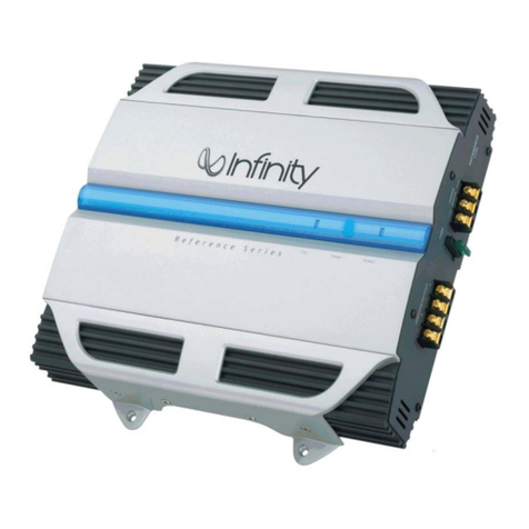
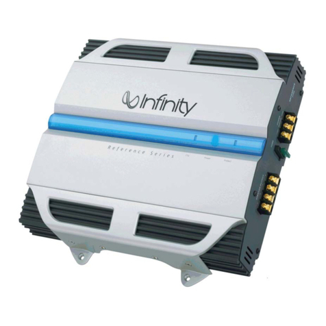
Infinity reference series User manual

Infinity

Infinity reference series User manual

Infinity RS KAPPA PS-8 User manual

Infinity

Infinity RS KAPPA PS-8 User manual

Infinity 1211a User manual

Infinity

Infinity 1211a User manual

Infinity Kappa 255A User manual

Infinity

Infinity Kappa 255A User manual

Infinity K600 User manual

Infinity

Infinity K600 User manual

Infinity kappa series User manual

Infinity

Infinity kappa series User manual

Infinity Kappa Center User manual

Infinity

Infinity Kappa Center User manual

Infinity Kappa 102a User manual

Infinity

Infinity Kappa 102a User manual

Infinity 7540a User manual

Infinity

Infinity 7540a User manual

Infinity Reference 1300A User manual

Infinity

Infinity Reference 1300A User manual

Infinity 7521A User manual

Infinity

Infinity 7521A User manual

Infinity 475a User manual

Infinity

Infinity 475a User manual

Infinity Kappa 202a User manual

Infinity

Infinity Kappa 202a User manual

Infinity 7520a User manual

Infinity

Infinity 7520a User manual

Infinity REF-704a User manual

Infinity

Infinity REF-704a User manual

Infinity 5760a User manual

Infinity

Infinity 5760a User manual

Infinity Basslink 4SC User manual

Infinity

Infinity Basslink 4SC User manual

Infinity 611A User manual

Infinity

Infinity 611A User manual

Infinity DPA 275 Programming manual

Infinity

Infinity DPA 275 Programming manual

Infinity 5760a User manual

Infinity

Infinity 5760a User manual

Infinity 310a User manual

Infinity

Infinity 310a User manual

Infinity 311a User manual

Infinity

Infinity 311a User manual

Infinity Beta Powersource Digital 300 Programming manual

Infinity

Infinity Beta Powersource Digital 300 Programming manual

Infinity Kappa 54a 4-Ch User manual

Infinity

Infinity Kappa 54a 4-Ch User manual

Popular Amplifier manuals by other brands

Steren AMP-025 instruction manual

Steren

Steren AMP-025 instruction manual

Yamaha DSP-A1000 Service manual

Yamaha

Yamaha DSP-A1000 Service manual

Shinybow USA SB-5654 instruction manual

Shinybow USA

Shinybow USA SB-5654 instruction manual

DS18 CANDY-XXL1B user manual

DS18

DS18 CANDY-XXL1B user manual

THORLABS BPA100 user guide

THORLABS

THORLABS BPA100 user guide

Precision Power PCX 250 owner's manual

Precision Power

Precision Power PCX 250 owner's manual

Ground Zero HYDROGEN GZHA 1.1200DXII owner's manual

Ground Zero

Ground Zero HYDROGEN GZHA 1.1200DXII owner's manual

Sony XM-SD61X operating instructions

Sony

Sony XM-SD61X operating instructions

Marantz SC-7S1 user guide

Marantz

Marantz SC-7S1 user guide

RTI AMR-350 user manual

RTI

RTI AMR-350 user manual

Monacor PA-4120 instruction manual

Monacor

Monacor PA-4120 instruction manual

Schumacher DSR101 user manual

Schumacher

Schumacher DSR101 user manual

Cloud 46 INTEGRATED Setup and installation guide

Cloud

Cloud 46 INTEGRATED Setup and installation guide

Musway MX Series manual

Musway

Musway MX Series manual

Crown DCi 8 600DA Operation manual

Crown

Crown DCi 8 600DA Operation manual

Two Notes VM-202 user manual

Two Notes

Two Notes VM-202 user manual

Audio enhancement CA-30 Quick start manual

Audio enhancement

Audio enhancement CA-30 Quick start manual

NAIM NAC S1 owner's manual

NAIM

NAIM NAC S1 owner's manual

manuals.online logo
manuals.online logoBrands
  • About & Mission
  • Contact us
  • Privacy Policy
  • Terms and Conditions

Copyright 2025 Manuals.Online. All Rights Reserved.