Infinity Modulus II Infinity User manual

MODULUS®II
HOME THEATER SYSTEM
Infinity Systems, Inc.
250 Crossways Park Dr.
Woodbury, New York 11797 Rev2 3/2005
S
ervice Manual

ACOUSTIC & ELECTRICAL SPECIFICATIONS:
• Nominal Impedance 8Ω
• Max Amp Power 125 watts*
• Frequency Response 80Hz – 20kHz (±3dB)
• Sensitivity 88dB (2.83V @ 1 meter)
• Crossover Frequency 2500Hz, 12dB/Octave
SYSTEM COMPONENTS:
• Cabinet MCC-1II (Not for Sale)
•Grille (for Charcoal) 244-040-00253B
(for Platinum) 244-040-00253W
• Low-Frequency Transducer Dual 4" (102mm) CMMD,
™
magnetically shielded
10PR80BZR-DW01
DC Resistance 3.3 ohms ±10%
• High-Frequency Transducer 3/4" (19mm) CMMD,
™
magnetically shielded
60DA20AD-DT01
DC Resistance 3.0 ohms ±10%
• Crossover Network 013-7500-00752
AURAL SWEEP TEST SPECIFICATIONS:
• System Aural Sweep Test 6.0V Input 80Hz to 20kHz
• L.F. Aural Sweep Test 5.0V Input 80Hz to 3kHz
• H.F. Aural Sweep Test 2.83V Input 2kHz to 20kHz
PHYSICAL SPECIFICATIONS:
• Dimensions 6-1/4" x 20-3/4" x 4-1/2"
(H x W x D) (159mm x 527mm x 114mm)
• Weight 8.3 lb (3.8kg) Each
WARRANTY:
• Refer to Warranty Statement packed with each product.
* The maximum recommended amplifier power rating will ensure
proper system headroom to allow for occasional peaks. We do not
recommend sustained operation at these maximum power levels.
MCC-1II
Infinity Systems, 250 Crossways Park Drive, Woodbury, New York 11797
6/04
The MCC-1
II
center is part of the
Modulus
II
Home Theater System.
373-000-00128
GIFT BOX 402-000-01774 (PLATINUM)
431-000-00957
(POLYFOAM SET TOP/BOTTOM)
PLASTIC BAG
431-000-00957
(POLYFOAM SET TOP/BOTTOM)
PLASTIC BAG
PLASTIC BAG
400-000-04383 (INNER CARTON)
431-000-00958
(POLYFOAM SET TOP/BOTTOM)
431-000-01014 (EPE)
431-000-00958
(POLYFOAM SET TOP/BOTTOM)
431-000-00956
(POLYFOAM SET TOP/BOTTOM)
431-000-00956
(POLYFOAM SET TOP/BOTTOM)
221-000-00344 (PVC COVER)
402-000-01845 (GIFT BOX)
BATTERY
398-ABS-00312
(TESTING DISK)
398-PVC-00263
(PVC SHEET)
033-000-00101 (ABS MICROPHONE)
406-000-00921 (OWNER’S MANUAL) & 405-000-00328 (WARRANTY CARD)
POSITIONED ON THE TOP OF INNER CARTON
398-FE-00264
(BUBBLE LEVEL AND
METAL PLATE)
402-000-01772 (CHARCOAL)
C2
2.7uf
100V
.110
H.F.
.187
50mm WHT
50mm BLU
L2
0.65mH
L1
2.4mH
C1
9.1uf
100V
.110
L.F.1
L.F.2
R1
3.3ohm
7W
INPUT
+
–
.205
60mm WHT
.110
60mm WHT
60mm GRN
GRN
YEL
TWEETER
60DA20AD-DT01
NETWORK
013-7500-00752
WOOFER
10PR80BZR-DW01
WOOFER
10PR80BZR-DW01
GRN
WHT
GRN
WHT
RED
BLK
.205
60mm GRN
PACKAGING MCC-1II WIRING DIAGRAM
MCC-1II SCHEMATIC
Technical Manual
MCC-1II
Rev2 03/05
406-000-05091 Owner's manual International Version
402-000-05164(PLATINUM
INTERNATIONAL VERSION)

1
10
15
16
11
2
17
18
14
3
5
8
4
4
6
7
12
13
MCC-1
II
Cabinet ± Not for Sale
MCC-1II
EXPLODED VIEW
Infinity Systems, 250 Crossways Park Drive, Woodbury, New York 11797
6/04
ITEM
NO. DESCRIPTION QTY. PART NO.
1. Front Grille (platinum) 1 244-040-00253W
(charcoal) 1 244-040-00253B
2. Left Aluminum Plate 1 Not For Sale
3. Grommet (platinum) 7327-010-00112W
(charcoal) 7 327-010-00112B
4. Screw 11 352-AM04020D603
5. Baffle 1 Not For Sale
6. Woofer 2 10PR80BZR-DW01
7. Screw 8 351-LM04006A565
8. Left Front Pad 1320-RUB-00182
ITEM
NO. DESCRIPTION QTY. PART NO.
9. Rear Cabinet (platinum) 1 Not for Sale
(charcoal) 1 Not for Sale
10. Tweeter 1 60DA20AD-DT01
11. Crossover 1 013-7500-00752
12. Left Terminal 1 215-000-00792
13. Right Terminal 1 215-000-00793
14. Back Rubber Pad 1 320-RUB-00183
15. Screw 2 352-CM03010D593
16. Screw 4 352-FM04014D602
17. Right Aluminum Plate 1Not For Sale
18. Right Rubber Pad 1 320-RUB-00189
Technical Manual
MCC-1II
TO SERVICE THE MCC-1II
1. Remove the grille.
2. Remove the (7) exposed rubber grille retainers; this can be accomplished by carefully pulling them out of their cavities with long-nosed pliers or
similar tool.
3. Remove the (7) Phillips screws underneath, that are now exposed.
4. Remove the (4) additional screws in their respective cavities at the rear of the housing.
5. Carefully lift the front baffle, with drivers attached, off the cabinet.
Rev2 03/05

ACOUSTIC & ELECTRICAL SPECIFICATIONS:
• Nominal Impedance 8Ω
• Max Amp Power 125 watts*
• Frequency Response 100Hz – 20kHz (±3dB)
• Sensitivity 86dB (2.83V @ 1 meter)
• Crossover Frequency 2500Hz, 12dB/Octave
SYSTEM COMPONENTS:
• Cabinet MS-1II (Not for Sale)
•Grille (for Charcoal) 244-040-00254G
(for Platinum) 244-040-00254W
• Low-Frequency Transducer 4" (102mm) CMMD,
™
magnetically shielded
10PR80BZR-DW01
DC Resistance 3.3 ohms ±10%
• High-Frequency Transducer 3/4" (19mm) CMMD,
™
magnetically shielded
60DA20AD-DT01
DC Resistance 3.0 ohms ±10%
• Crossover Network 0B-1500-00751
AURAL SWEEP TEST SPECIFICATIONS:
• System Aural Sweep Test 6.0V Input 100Hz to 20kHz
• L.F. Aural Sweep Test 5.0V Input 100Hz to 3kHz
• H.F. Aural Sweep Test 2.83V Input 2kHz to 20kHz
PHYSICAL SPECIFICATIONS:
• Dimensions – Shelf Position 11" x 5-1/2" x 4-1/2"
(H x W x D) (279mm x 140mm x 114mm)
Wall Position 9-3/4" x 5-1/2" x 5-3/4"
(248mm x 140mm x 146mm)
• Weight 5.1 lb (2.3kg) Each
(4 pcs. in the Modulus Home
Theater System)
(1 pc. in the Modulus MS-1II
Single Pack)
WARRANTY:
• Refer to Warranty Statement packed with each product.
* The maximum recommended amplifier power rating will ensure
proper system headroom to allow for occasional peaks. We do not
recommend sustained operation at these maximum power levels.
MS-1II
Infinity Systems, 250 Crossways Park Drive, Woodbury, New York 11797
6/04
The MS-1
II
satellites are part of the
Modulus
II
Home Theater System.
373-000-00128
GIFT BOX 402-000-01774 (PLATINUM)
431-000-00957
(POLYFOAM SET TOP/BOTTOM)
PLASTIC BAG
431-000-00957
(POLYFOAM SET TOP/BOTTOM)
PLASTIC BAG
PLASTIC BAG
400-000-04383 (INNER CARTON)
431-000-00958
(POLYFOAM SET TOP/BOTTOM)
431-000-01014 (EPE)
431-000-00958
(POLYFOAM SET TOP/BOTTOM)
431-000-00956
(POLYFOAM SET TOP/BOTTOM)
431-000-00956
(POLYFOAM SET TOP/BOTTOM)
221-000-00344 (PVC COVER)
402-000-01845 (GIFT BOX)
BATTERY
398-ABS-00312
(TESTING DISK)
398-PVC-00263
(PVC SHEET)
033-000-00101 (ABS MICROPHONE)
406-000-00921 (OWNER’S MANUAL) & 405-000-00328 (WARRANTY CARD)
POSITIONED ON THE TOP OF INNER CARTON
398-FE-00264
(BUBBLE LEVEL AND
METAL PLATE)
402-000-01772 (CHARCOAL)
C2
1.8uf
100V
.110
H.F.
.187
100mm WHT
100mm BLU
L2
0.40mH
L1
1.2mH C1
12uf
100V
.110
L.F.
R1
2.7ohm
7W
INPUT
+
—
.205
120mm WHT
120mm GRN
RED
YEL
TWEETER
60DA20AD-DT01
NETWORK
0B-1500-00751 WOOFER
10PR80BZR-DW01
RED
YEL
RED
RED/BLK
PACKAGING MS-1II WIRING DIAGRAM
MS-1II SCHEMATIC
Technical Manual
MS-1II
Rev2 03/05
402-000-05164(PLATINUM
INTERNATIONAL VERSION)
406-000-05091 Owner's manual International Version

1
2367
16
17
18
20
21
22
24
26
810 11 12
13
14
9
25
27
28
23
19
4 5 MS-1
II
Cabinet – Not for Sale
MS-1II
EXPLODED VIEW
Infinity Systems, 250 Crossways Park Drive, Woodbury, New York 11797
6/04
ITEM
NO. DESCRIPTION QTY. PART NO.
1. Front Grille (platinum) 1 244-040-00254W
(charcoal) 1 244-040-00254G
2. Aluminum Face Plate 1 Not For Sale
3. Grommet (platinum) 4 327-010-00112W
(charcoal) 4 327-010-00112B
4. Screw 6 352-AM04020D603
5. Baffle 1 Not For Sale
6. Woofer 1 10PR80BZR-DW01
7. Screw 4 351-LM04006A565
8. Tweeter 1 60DA20AD-DT01
9. Screw 2 352-CM03010D593
10. Screw 4 352-FM04014P602
11. Crossover 1 0B-1500-00751
12. Screw Cap 1 354-HM05418
13. Skidproof Sheet 1 355-L0507239
14. Washer Sheet 1 355-P0510240
ITEM
NO. DESCRIPTION QTY. PART NO.
15. Rear Cabinet (platinum) 1 Not for Sale
(charcoal) 1 Not for Sale
16. Left Terminal 1 215-000-00792
17. Right Terminal 1 215-000-00793
18. Bracket Ball 1 325-AL-00187
19. Aluminum Plate (platinum) 1 320-AL-00184-0WA
(charcoal) 1 320-AL-00184-0W
20. Aluminum Base 1 320-AL-00185
21. Back Foot Base 1 320-RUB-00186
22. Rubber Strip 1 398-RUB-00249
23. Bracket Holder 1 320-AL-00416
24. Screw 1 351-KM04012A578
25. Wrench Box 1 398-ABS-00250
26. Wrench 1 399-FE-00618
27. Screw 1 351-AM03005A015
28. Iron Plate 1 399-FE-00619
Technical Manual
MS-1II
TO SERVICE THE MS-1II
1. Remove the grille.
2. Remove the (4) exposed rubber grille retainers; this can be accomplished by carefully pulling them out of their cavities with long-nosed pliers or
similar tool.
3. Remove the (4) Phillips screws underneath, that are now exposed.
4. Remove the (2) additional screws in their respective cavities at the rear of the housing; push the wall bracket to one side for access with a
screwdriver bit.
5. Carefully lift the front baffle, with drivers attached, off the cabinet. Caution – do not pull on the corner of the metal baffle shield, or you may
dislodge it from the front baffle.
Rev2 03/05
320-AL-00187

1
4
10
11
9
13
14
3
8
12
6
7
3
5
3
2
MSW-II Subwoofer
EXPLODED VIEW
ITEM
NO. DESCRIPTION QTY. PART NO.
1. GRILLE (CHARCOAL) 1 244-120-00268-0YA
(PLATINUM) 244-120-00268G
2. GRILLE CUP (Charcoal) 4 327-RUB-00112B
(Platinum) 327-RUB-00112W
3. WOOFER/AMPLIFIER/BAFFLE 25 352-FM04020D605
SCREWS
4. FRONT BAFFLE (Charcoal) 1 243-120-00399B
(Platinum) 1 243-120-00399W
5. 12" WOOFER C.M.M.D.,SHIELDED, 1 30PR14BW-DW01
DCR = 3.5Ω±10%
6. MSW-II SUBWOOFER CABINET 1 Not for Sale
(CHARCOAL OR PLATINUM)
ITEM
NO. DESCRIPTION QTY. PART NO.
7. AMPLIFIER ASSEMBLY 1 Not for Sale
8. FOOT (Charcoal) 4 320-ABS-00193B
(Platinum) 4 320-ABS-00193W
9. FOOT PAD (Charcoal) 4 320-RUB-00192B
(Platinum) 4 320-RUB-00192W
10. PORT TUBE 1 249-ABS-00158
11. FOOT SCREW 4 352-HM05025D606
12. WIRING HARNESS (AMP-LEVEL POT)1 165-50400HH4
13. LEVEL CONTROL PCB 1 015-AA000-00113
14. LEVEL CONTROL SCREWS 3 352-CM03509D439
MSW-II Subwoofer
8
MSW-II

MODULUS® II HOME THEATER SYSTEM
SERVICE MANUAL
Infinity Systems, Inc.
250 Crossways Park Dr.
Woodbury,New York11797 Rev23/2005
MODULUSII SUB

- CONTENTSMODULUSII SUB -
BASIC SPECIFICATIONS …………………………………….…….……………..
DETAILED MSW-IISPECIFICATIONS ……………………………………….…..
CONTROLS AND CONNECTIONS…………………………………….…..………..
OPERATION….……………………………………………………………………..….
AMPLIFIER EXPLODEDVIEW………………………………………..……………..
EXTERNAL/MECHANICAL PARTSLIST…………….………………....……
MSW-IITEST PROCEDURE………………………………………..………………..
ELECTRICALPARTSLIST……………….……………………………………….
PCBDRAWINGS……………….…………..…………………………………..….…
SEMICONDUCTOR PINOUTS……………………………………………….……..
SCHEMATICS ……………………………………………………………………...
MODULUS IIPACKING………………………………………………………………
Basic Specifications
Modulus MSW-II Powered Subwoofer
Frequency Range: 27Hz – 100Hz (±3dB)
Amplifier Output: 300 watts RMS, 600 watts peak
Low-Frequency Driver: 12" C.M.M.D.,magnetically shielded
Crossover Frequency: 100 Hz (12 dB per octave)
Dimensions (H x W x D): 16-1/2" x 14-1/2" x 18-1/8"
(419mm x 368mm x 460mm)
Weight: 44 lb (20 kg)
Infinity continually strives to update and improve existing products, as well as create new ones. The specifications
and construction details in this and related Infinity publications are therefore subject to change without notice.
MSW-II

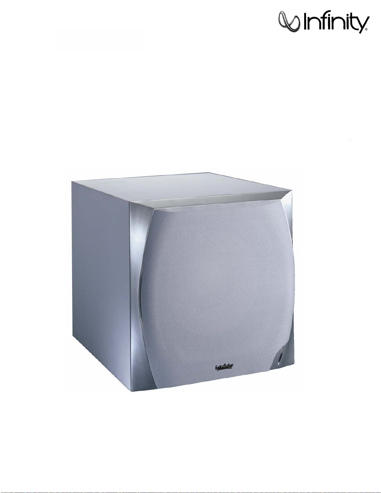
Modulus subwoofer MSW- II 300W Powered Sub/ Plate Amp
LINE VOLTAGE Yes/No Hi/Lo Line Nom. Unit Notes
US 120vac/60Hz Yes 108-132 120 Vrms Normal Operation
EU 230vac/50-60Hz Yes 207-264 230 Vrms Normal operation, MOMS required
Parameter Specification Unit QA Test
Limits Conditions Notes
Amp Section
Type (Class AB, D, other) D ---
Load Impedance (speaker) 4 Ohms Nominal Z-curve required
Rated Output Power 300 Watts Regulated 120 V line
THD@ Rated Power 1 % 22k filter, 50Hz 300W
THD @ 1 Watt 0.2 % 22k filter, 50Hz
DC Offset undefined mV-DC < 20 @ Speaker Outputs
Damping factor 20 N/A > 15 measured at 50 Hz
Input Sensitivity
Line/Hi Level Input Phase N/A
Line Input 400 mVrms 300 W @ 50Hz 1 input driven
Signal to Noise
SNR-A-Weighted 100 dBA relative to rated power A-Weighting filter
SNR-unweighted 70 dBr relative to rated power 22k filter
SNR rel. 1W-unweighted 60 dBr relative to 1W Output 22k filter
Residual Noise Floor 2 mVrms Volume @max, using RMS reading DMM/VOM (or A/P)
Residual Noise Floor 1
mVrms(max)
Volume @max, w/ A/P Swept Bandpass Measurement (Line freq.+ harmonics)
Input Impedance Line Input 5 k ohms Nominal
Active Filters
Low Pass (fixed or variable) FIXED --
Frequency 100 Hz
Slope 24 dB/Octave
Q Butterworth Damping
Subsonic filter (HPF) fixed --
Frequency 20 - 35 Hz
Slope 12 dB/Octave
Q 0.5 - 2.5 Damping
Friend Circuit FIXED --
Frequency 62.7 Hz Hz notch filter
Slope 12 dB/Octave
Q 2.5 Damping
Special filter RABOS --
Switches
Main Power On/Off Switch YES --
Type push-button -- Located on amp plate
RABOS on/off YES --
Type mini toggle --
Polarity Switch YES -- "Off": 0°; "On": 180°
Type mini toggle -- Locate at amp plate
Low Pass on/off YES
Type mini toggle -- Locate at amp plate
Limite
r
(yes/no) YES compressor and limiter
THD at Max. Output Power less than 2 % Maximum Output Power Maximum THD as a result of limiting.
Output Volume Control
Volume Control Pot YES -- harness for pot and LED to be remotely mounted
Taper (lin/log) log A taoer --
@ minimum setting no output
Input/Output Configuration
Line In (L,C,R,AC3,Mono) Stereo -- RCA phono jack, gold plated
LFE In YES -- Shared with "R" Line In jack
Hi Level Out YES --
Signal Sensing (ATO)
Auto-Turn-On (yes/no) YES --
ATO Input Test Frequency 100 Hz
ATO Input Threshold 2 mV typ. LPF "On", BOS "Off"
ATO Low Pass cutoff 400 Hz 450 ATO-LPF for noise immunity LPF "On", BOS "Off"
ATO Turn-on time 1 ms 10 Amp connected and AC on, then input signal applied ( 1 W output )
Auto Mute / Turn-OFF Time 10 minutes 5 < t < 15 Time before muting, after signal is removed
MSW-II

Power on Features
Power on Delay time greater than 2 sec. AC Power Applied
Power on LED YES -- Bi-color LED located adjacent to volume control knob
Normal On/Off green / red color ATO mode only
ATO -- color "Active": green; "Standby": red
Transients/Pops
ATO Transient 5 mV-peak @ Speaker Outputs
Turn-on Transient 30 mV-peak @ Speaker Outputs AC Line cycled from OFF to ON
Turn-off Transient 30 mV-peak @ Speaker Outputs AC Line cycled from ON to OFF
Efficiency
Stand-by Input Power 12 Watts typ. @ nom. line voltage
AC Power Cons.@1W 13 Watts typ. @ nom. line voltage
Power Cons.@rated power 375 Watts typ. @ nom. line voltage Input power measured is REAL Watts, not VA
Efficiency 70 % typ. @ nom. line voltage
Protection
Short Circuit Protection YES -- Direct short at output
Thermal Protection YES -- threshold ~ 65 deg. C at panel
DC Offset Protection YES -- DC present at Speaker Out leadRelay for driver/fire protection
Line Fuse Rating ( 120 V ) 3.15 Amps Type ADL or MDL Panel mount fuse holder
MSW-II

MODULUS II HOMETHEATER SYSTEM
S
UBWOOFER
C
ONTROLS
Rear Panel
Front Panel
ª
LR
POWER
ON OFF
ON OFF
180°0°
Freq.
Level INPUT
R.A.B.O.S.™
Controls
R.A.B.O.S.
PHASE
LOW PASS
LFE
Width
™¡
∞
§
¶
£
¢
•
FUSE
T5A L/250V AC 120V~60Hz
75 Watts
Modulus MSW-II
This unit is designed to become quite warm,
during normal operation. NRTL/C
CSA22-2 NO. 1
UL 1492
¡R.A.B.O.S.On/Off Switch
™Center-FrequencyAdjustment
£BandwidthAdjustment
¢R.A.B.O.S.Level
∞Phase Switch
§Low-Pass Filter Selector
¶Line-Level Inputs
•Power Switch
ªSubwoofer Level Control
A Few Suggestions
We recommend that you do not operate your speakers or
subwoofer with the bass,treble and loudness controls set to
full boost.This will place undue strain on your electronics and
speakers and could damage them.
The volume control setting on your processor/preamp or receiver
is not a specific indication of the overall loudness level of the
speakers.The only important consideration is the loudness level
at which the system can be played,regardless of where the
volume control is set.
Always turn down the volume control setting on your processor/
preamp or receiver when changing a cassette or CD,or switching
inputs toAM or FM operation.Excessively loud transients (clicks
or popping sounds) can damage the satellite speakers and
possibly the subwoofer.
Important!
Whenever changing cables,pulling plugs,etc.,ALWAYSTURN OFF
ALL EQUIPMENT,including the subwoofer.This prevents transients
from entering the speakers and prevents electrical energy from
reaching you.Keep all connections out of the reach of children.
Room Adaptive Bass
Optimization System
(R.A.B.O.S.) Controls
MSW-II

MODULUS II HOMETHEATER SYSTEM
If your receiver/processor has subwoofer
outputs for the left and right channels:
• Set Low-Pass Filter §to“On.”
RECEIVER/PROCESSOR
LR
POWER
ON OFF
ON OFF
180°0°
Freq.
Level INPUT
R.A.B.O.S.™
Controls
R.A.B.O.S.
PHASE
LOW PASS
LFE
Width
™¡
∞
§
¶
£
¢
•
FUSE
T5A L/250V AC 120V~60Hz
75 Watts
Modulus MSW-II
This unit is designed to become quite warm,
during normal operation. NRTL/C
CSA22-2 NO. 1
UL 1492
S
UBWOOFER
C
ONNECTIONS
If you have a Dolby* Digital or DTS®receiver/processor
with a low-frequency-effects (LFE) output:
•Set Low-Pass Filter §to“Off”.
SUBWOOFER OR
LFE OUTPUT
LR
POWER
ON OFF
ON OFF
180°0°
Freq.
Level INPUT
R.A.B.O.S.™
Controls
R.A.B.O.S.
PHASE
LOW PASS
LFE
Width
™¡
∞
§
¶
£
¢
•
FUSE
T5A L/250V AC 120V~60Hz
75 Watts
Modulus MSW-II
This unit is designed to become quite warm,
during normal operation. NRTL/C
CSA22-2 NO. 1
UL 1492
MSW-II

MODULUS II HOMETHEATER SYSTEM
Surround Modes
When using the Modulus II system in a Dolby Pro Logic* home
theater system,make sure the receiver’s center channel mode is
set to“Normal.”When using the Modulus II system in a Dolby
Digital or DTS home theater system,make sure the receiver’s
speaker modes are set to“Small.”
Some Dolby Digital-equipped receivers/processors offer different
setup options for each source or surround mode: e.g.,CD-stereo,
videotape,Dolby,Pro Logic.In each case,follow your equipment’s
instructions to ensure that the subwoofer output is turned on and
that the speakers are set to“Small”in each mode.
Power On
Plug your Modulus II subwoofer’sAC cord into a wall outlet.Do not
use the outlets on the back of the receiver.
Initially set the subwoofer’s Level Control ªto the“O”position.
Turn on your sub with the Power Button •on the rear panel.
Auto On/Standby
With the Power Button •in the ON position,the Level Control
ªon the front panel will remain backlit in red or green to
indicate the On/Standby mode of the subwoofer.
RED = STANDBY (No signal detected,Amp Off)
GREEN = ON (Signal detected,Amp On)
The subwoofer will automatically enter the Standby mode after
approximately 10 minutes when no signal is detected from your
system.The subwoofer will then power ON instantly when a signal
is detected.During periods of normal use the Power Button •
can be left on.You may turn off the Power Button •during
extended periods of nonoperation:e.g.,when you are away on
vacation.
Adjust Level
Turn on your entire audio system and start a CD or movie sound-
track at a moderate level.Turn your subwoofer’s Level Control ª
up to the“5”position (half way).If no sound emanates from the
subwoofer,check theAC-line cord and input cables.Are the
connectors on the cables making proper contact? Is theAC plug
connected to a“live”receptacle? Has the Power Button •been
pressed to the“On”position? (Note:The Level Control ªon the
front panel will turn green when the power is on.) Once you have
confirmed that the subwoofer is active,proceed by playing a
sound source.Use a selection that has ample bass information.
Set the overall volume control of the preamplifier or stereo to a
comfortable level.Adjust the subwoofer’s Level Control ªuntil
you obtain a pleasing blend of bass.Bass response should not
overpower the room but rather be adjusted so there is a
harmonious blend across the entire musical range.Many users
have a tendency to set the subwoofer volume too loud,adhering
to the belief that a subwoofer is there to produce lots of bass.
This is not entirely true.A subwoofer is there to enhance bass,
extending the response of the entire system so the bass can be
felt as well as heard.However,overall balance must be maintained
or the music will not sound natural.An experienced listener
will set the volume of the subwoofer so its impact on bass
response is always there but is never obtrusive.
Phase Control
The Phase Switch ∞determines whether the subwoofer
speaker’s piston-like action moves in and out with the main
speakers,0˚,or opposite the main speakers,180˚.Proper phase
adjustment depends on several variables such as room size,
subwoofer placement and listener position.Adjust the phase
switch to maximize bass output at the listening position.
Final Positioning
After correctly connecting the Modulus II system and verifying
that both the subwoofer and all satellite speakers are playing,it
is time to optimize the system for your particular listening room.
Earlier,you placed the subwoofer in its general location.Finding
the exact location for optimum performance sometimes only
involves moving the speakers up to a few inches in any direction.
We urge you,therefore,to experiment with placement,if possible,
until your speakers deliver their full potential.
O
PERATION
MSW-II

MSW-II
MSW-II Subwoofer
amplifier exploded view

INFINITY MODULUSII 300W 230V
PART NO. DESCRIPTION QTY REFERENCE
051-A00444C01
PCB ASS'Y OF CVSUB50 230V 1
051-A00448A
PCB ASS'Y OF MSW-II 230V 1
051-A00448B
PCB ASS'Y OF CVSUB50/230V EMC 1
123-11k4drh bobbin K4DRH 16*28.5*9 1
123-11k4dt bobbin F4DT 31*16*19 1
150-r1107002 power transformer TT0930303600 1
152-v60202a05 line cord VDE 6FT 2PIN 1
153-v213515 ac outlet&sock et (IEC JK 2P W/FUSE) 1
154-v25006t0 fuse 2.5A 250V 20mm TIME LAG VDE 1
162-10102009 WIRE UL/CSA 1617#32 100mm RED 3
162-50159003 wire 150mm AWG240 1P108
163-11009 wire 100mm 8
163-11809 wire tie 180mm*3.6 2
165-50701xx01 wire ass'y 700mm UL2464#22 1P101
166-5070a4bd speaker wire 700mm#18 UL1015 1
180-prf1003a Switch ROCK RF-1003 1
193-0s4211 INSULATOR(INSULATION SPACER)42*11 1
193-201612tr INSULATOR T0-220 16mm*12mm 1
193-201815t2 INSULATOR 2
PREAMP / INPUT PCB ASS'Y 230V
PART NO. DESCRIPTION QTY REFERENCE
109-ltsc103j0 Thermister TSC05103J 1R237
110-12621j15 resistor 620O1/2W ±5% 15mm 1R238
110-20152j20 resistor 1.5K 2W ±5% CF 20mm KINK 1R208
113-500rlj10 resistor 0.1O5W ±5% 2R224,225
115-h103a203 variable resistor RV16A01-20-15K-A10K-3E 2R158,R177
115-h103c201 variable resistor RV16A01-20-15K-C10K-3E 1R163
116-142003f26 metal film resistor 200K 1/4W±1% MF 26mm TAP 1R209
116-201211f20 metal film resistor 1.21K 2W±1% 20mm 1R104
129-a104j633 disc capacitor 0.1U 63V±5% MSC TAP 1C118
135-4228m35 electrolytic2200UF35V ±20% 2C170,171
135-4688m80 electrolytic6800U 80V ±20% 2C168,C169
162-10149001 wire ass'y 140mm AWG28 1P107
162-50150002 wire ass'y 150mm AWG26 BLCK 1P102
162-50150003 wire ass'y 150mm AWG26 BLCK 2P103,P104
171-udhss124d Relay 5A 24V UDH-SS124D 1K101
174-0rcb202vag RCA JACK RCA-209 1JK102
175-1c02p01 Wire connector&base 2 PIN PITCH=2.5mm 3P106,108,101
175-1c04v01 Wire connector&base 4 PIN PITCH=2.5mm 1P101
175-1c06v01 Wire connector&base 6 PIN PITCH=2.5mm 1P105
175-1d02v01 Wire connector&base2PIN PITCH=3.96mm 1P112
175-1d05v01 Wire connector&base 3.96mm 1P113
180-t000ts81 TACT switch L101 T2 3SW102,SW103,SW104
190-06m4558d I.C. OPA 4558D 2U101,U103
190-161m324n *I.C.LM324N 2U106,U107
190-16t1072n I.C. [email protected] 1U105
190-16t1074cn I.C TL074CN ST 2U102,U104
192-153mpf102 I.C FAIRCHILD MPF102 1Q107
192-991d669a transistor HI-SINCERITY HSD669A(192011d669a) 1Q116
192-992b649t transistor HSB649T 1Q118
197-00db103g diode 1A 200V DF02M DB103G 1D124
197-00kbu1003 diode 10A 200V KBU1003 1D123
197-101n4002 diode IN4002 1D114

MOTHER PCB ASS'Y 230V (+input pcb, caps,res,dio..)
PART NO. DESCRIPTION QTY REFERENCE
110-14152j26 resistor 105K 1/4W±5% CF 26mm TAP 1R150
110-16101j26 resistor 100O1/6W±5% CF 26mm TAP 4R112,R113,R151,R152
110-16102j26 resistor 1K 1/6W±5% CF 26mm TAP 4R210,R239,R264,R140,R196
110-16103j26 resistor 10K 1/6W±5% CF 26mm TAP 20 R227,229,230,231,232,233,260,261,263,118,126,129
133,136,146,149,199,196,216,191
110-16105j26 resistor 1M 1/6W±5% CF 26mm TAP 2R145,R181
110-16106j26 resistor 10M 1/6W±5% CF 26mm TAP 1R186
110-16151j26 resistor 150O1/6W±5% CF 26mm TAP 1R139
110-16153j26 resistor 15k 1/6W±5% CF 26mm TAP 2R247,R249
110-16154j26 resistor 150k 1/6W±5% CF 26mm TAP 1R138
110-16182j26 resistor 1.8k 1/6W±5% CF 26mm TAP 1 R248
110-16183j26 resistor 18k 1/6W±5% CF 26mm TAP 1 R147
110-16203j26 resistor 20k 1/6W±5% CF 26mm TAP 1 R200
110-16221j26 resistor 220O1/6W±5% CF 26mm TAP 2R119,R120
110-16222j26 resistor 2.2K 1/6W±5% CF 26mm TAP 2R242,R245
110-16223j26 resistor 22K 1/6W±5% CF 26mm TAP 5R218,R220,R223,R141,R148
110-16274j26 resistor 270K 1/6W±5% CF 26mm TAP 1 R240
110-16333j26 resistor33K 1/6W±5% CF 26mm TAP 1 R211
110-16391j26 resistor390O1/6W CF 26mm TAP 2R243,R246
110-16432j26 resistor4.3K 1/6W±5% CF 26mm TAP 1 R254
110-16472j26 resistor4.7K 1/6W±5% CF 26mm TAP 6R217,R219,R222,R144,R213,R250
110-16473j26 resistor47K 1/6W±5% CF 26mm TAP 2R221,R137
110-16474j26 resistor470K 1/6W±5% CF 26mm TAP 1 R143
110-164r7j26 resistor4.7O1/6W±5% CF 26mm TAP 1 R153
110-16683j26 resistor68k 1/6W±5% CF 26mm TAP 1 R212
112-14101j26 fuse resistor 1/4W 100ohm 5% 2R241,R244
116-141r00j26x metal film resistor 1.00O1/4W±5% MO 26mm TAP 2R256,R255
116-161000f26 metal film resistor 100O1/6W±1% MF 26mm TAP 1 R154
116-161001f26 metal film resistor 1K 1/6W±1% MF 26mm TAP 3R180,187,194
116-161002f26 metal film resistor 10K 1/6W±1% MF 26mm TAP 12 R130,131,132,159,160,166,171,173,178,192,234,235
116-161502f26 metal film resistor 15.0K 1/6W±1% MF 26mm TAP 1 R188
116-161103f26 metal film resistor 110K±1% MF 1/6W 26mm TAP 1 R174
116-161210f26 metal film resistor 121O1/6W±1% MF 26mm TAP 1 R252
116-161301f26 metal film resistor 1.30K 1/6W MF 26mm TAP 3R226,R228,R236
116-161504f26 metal film resistor 1.5M 1/6W±1% MF 26mm TAP 1 R142
116-161622f26 metal film resistor 16.2k 1/6W MF 26mm TAP 1 R188
116-161742f26 metal film resistor 17.4k 1/6W±1% MF 26mm TAP 4R124,R125,R127,R128
116-161822f26 metal film resistor 18.2k 1/6W±1% MF 26mm TAP 1 R214
116-162001f26 metal film resistor 2.00k 1/6W±1% MF 26mm TAP 2R215,R202
116-162052f26 metal film resistor 20.5k 1/6W±1% MF 26mm TAP 2R197,R198
116-162211f26 metal film resistor 2.21k 1/6W±1% MF 26mm TAP 1R172
116-162212f26 metal film resistor 22.1k 1/6W±1% MF 26mm TAP 3R193,R204,R206
116-162492f26 metal film resistor 24.9k 1/6W±1% MF 26mm TAP 2R257,R258
116-162671f26 metal film resistor 2.67k 1/6W±1% MF 26mm TAP 1R155
116-163323f26 metal film resistor 332k 1/6W±1% MF 26mm TAP 1R195
116-163400f26 metal film resistor 340O1/6W±1% MF 26mm TAP 2R164,R169
116-163571f26 metal film resistor 3.57K 1/6W±1% MF 26mm TAP 1R157
116-163923f26 metal film resistor 392K 1/6W±1% MF 26mm TAP 1R201
116-164320f26 metal film resistor 432O1/6W±1% MF 26mm TAP 1R265
116-164751f26 metal film resistor 4.75K 1/6W±1% MF 26mm TAP 2R109,R110
116-164752f26 metal film resistor 4.75K 1/6W±1% MF 26mm TAP 2R121,R122
116-164992f26 metal film resistor 49.9K 1/6W±1% MF 26mm TAP 1R135
116-165231f26 metal film resistor 5.23K 1/6W±10% MF 2R205,R207
116-165232f26 metal film resistor 52.3K 1/6WMF 26mm TAP 1R190

MOTHER PCB ASS'Y 230V (+input pcb, caps,res,dio..)
PART NO. DESCRIPTION QTY REFERENCE
116-165400f26 metal film resistor 540O1/6W MF 26mm TAP 1R175
116-166041f26 metal film resistor 6.04K 1/6W MF 26mm TAP 2R165,R170
116-166800f26 metal film resistor 680O1/6W±1% MF 26mm TAP 1R176
116-166813f26 metal film resistor 681K 1/6W±1% MF 26mm TAP 1R262
116-168250f26 metal film resistor 825O1/6W±1% MF 26mm TAP 2R161,R167
116-168661f26 metal film resistor 8.66K 1/6W±1% MF 26mm TAP 1R134
116-169311f26 metal film resistor 9.31K 1/6W±1% MF 26mm TAP 2R189,R179
129-a102j633 metaline cap 0.001uF 63V ±5% MSC TAP 1C148
129-a103j633 metaline cap 10NF 63V 1C183
129-a104j633 metaline cap 0.1U 63V ±5% MSC TAP 6C116,C137,C138,C139,C143,C118
129-a223j633 metaline cap 0.022U 63V ±5% MSC TAP 1C150
129-a224j633 metaline cap 0.22uF 63V ±5% MSC TAP 2C121,C122
129-a473j633 metaline cap 0.047U 63V ±5% MSC TAP 3C117,C119,C149
130-2b102k503 disc capacitor 1000P 50V ±10% TAP 3C165,C181,C182
130-2b221k503 disc capacitor 220P 50V ±10% TAP 3C107,C108,C128
130-3f104z503 disc capacitor 0.1U 50V +80/-20% TAP 15 C163,164,112,114,124,125,130,133,135,
144,145,146,147,153,154
130-3f473m503 disc capacitor 0.047U 50V ±20% TAP 1C180
130-ch101j503 disc capacitor 100P 50V ±5% TAP 2C159,C160
130-s1101k53 disc capacitor 100P 50V SL ±10% TAP 2C110,C120
130-s1470k503 disc capacitor 47P 50V ±10% TAP 1C127
135-3105m50 electrolytic cap 1U 50V ±20% TAP 1C126
135-3106m50 electrolytic cap 10uF 50V ±20% TAP 4C109,C111,C123,C129
135-3107m16 electrolytic cap 100uF 16V ±20% TAP 7C166,C167,C113,C115,C132,C134,C136
135-3107m25 electrolytic cap 100U 25V ±20% TAP 1C152
135-3226m50 electrolytic cap 22U 50V ±20% TAP 3C161,C162,C151
135-3227m10 electrolytic cap 220U 10V ±20% TAP 2C156,C157
139-3227m16 low leakage ec 220uF 16V±20% TAP 2C155,C131
140-rx103ka03 multi-layer capacitor 10nF 100V X7R 10% 1C174
140-rx473kb03 multi-layer capacitor 47nF 200V X7R ±10% TAP 2C172,C173
161-006050 JUMPER WIRE 5mm 78
190-161431c1p1 IC TL431CLP 1D115
192-027c1815gr transistor 2SC1815GR TAP 7Q101,Q102,Q103,Q110,Q112,Q114,Q117
192-028a1015gr transistor 2SA1015GR TAP 3Q111,Q113,Q115
192-1572n5551 transistor FSC 2N5551 TAP 1Q109
192-1582n5401 transistor FSC 2N5401 AI-PNP 350V 500mA TO-92 1Q108
197-031n4148 diode 100mA 75V SIGNAL IN4148 ROHM TAP 14 D118,119,120,121,125,126,105,106,
108,109,110,111,112,113,117
199-15000565 zener diode 5.6V 1/2W 52mm TAP 1D116
199-15000825 zener diode 8.2V 1/2W 52mm TAP 1D130
199-15001505 zener diode 15V 1/2W 52mm TAP 1D122
199-15002005 zener diode 20V 1/2W 52mm TAP 1D129

CLASS D-AMP PCB ASS'Y 230V
PART NO. DESCRIPTION QTY REFERENCE
112-10180j00 fuse resistor FMF 1W 18O5% 1
122-13151k0190 CHOKE SA-500-280(PT16018*151MAA) 1L1
122-14300k4 Ferrite core LD1215*300KU±10% 1L2
128-e106ma01-s Non-Polar EC. 10uF 100W 20% 2C16,C17
130-s1681kb03 disc capacitor SL 680PF 200V 1
132-104kb50 mylar capacitor 0.1U±10% 250V LS-10.mm MD 1C20
132-105kb50 mylar capacitor 1UF 250V±10% LS-10.mm MD 1C40
156-h010005 tube 5mm ?1 1C40
156-h010020 tube 1 ?*20mm 1C40
163-11009 WERE TIE 100mm 2
175-9f40hr2 wire connector 40PIN PITCH=2.54mm HR2*40 0,2
192-232irf9640 transistor FET IRF9640 IR P-CH TO220 2Q10,Q10B
192-233f640n transistor FET IRF640n INTERNATIONAL 1Q11
118-12061001j SMD resistor 1.00K 1206 5% 1R2
118-12061002j SMD resistor 10.0K 1206 5% 6R25,29,30,30B,7,9
118-120610r0j SMD resistor 10.0O1206 5% 4R20,20B,22,23
118-12062002j SMD resistor 20.0K 1206 5% 1R26
118-12062201j SMD resistor 2.20K 1206 5% 19
R6,13,16,31,33,34,35,36,37,38,39,40,
41,42,43,44,45,46,32
118-12062204j SMD resistor 2.20M 1206 5% 1R4
118-12062701j SMD resistor 2.70K 1206 5% 1R10
118-12063000j SMD resistor 300.0O1206 5% 1R24
118-12063301j SMD resistor 3.30K 1206 5% 5R1,14,15,27,28,
118-12063902j SMD resistor 39.0K 1206 5% 1R3
118-12064700j SMD resistor 470O1206 5% 3R8,11,21
118-12064701j SMD resistor 4.70K 1206 5% 2R5,12
141-c0101k50 SMD cakpacitor 100pF 50V 10% 1206 NPO 1C4
141-c0220k50 SMD cakpacitor22pF 50V 10% 1206 SMT NPO 1C5
141-c0561k50 SMD cakpacitor 560pF 50V 10% 1206 NPO 1C6
141-c5104m50 SMD cakpacitor 1206 Y5V 0.1uF 50V±20% 8C2,3,7,8,9,10,11,15
141-c7223K50 SMD cakpacitor 0.022uF 50V 10% 1206 X7R 1C13
141-d7104ka0 SMD cakpacitor 0.1uF 100V 10% 1210 X7R 4C12,14,18,19,
190-16t1072dts SMD I.C.TL072CDT SGS THOMSON 1IC1
192-09124126qs SMD transistor 2SC2412K-T146Q/R ROHM 2Q1,4
192-09139066rs SMD transistor 2SC3906K-T146Q/R ROHM 2Q2,8
192-091sc4672 SMD transistor 2SC4672K(MPT3) ROHM 1Q5B
192-09210376qs SMD transistor 2Sa1037K-T146Q/R ROHM 2Q7,9
192-09215146rs SMD transistor 2Sa1037K-T146R ROHM 1Q3
192-1582n5401 SMD transistor FSC 2n5401 AI-PNP 350V500mA TO-92 1Q6B
197-03rls4148s SMD diode RLS4148-TE11 ROHM 8D1,2,3,4,5,5B,6,20
199-15000563s zener diode5.6V 5% PHILIPS 2Z1,2
199-150001203s zener diode121V 5% PHILIPS 4Z3,4,5,6,
EMC PCB ASS'Y 230V 051-A00448B
PART NO. DESCRIPTION QTY REFERENCE
104-a00448b00v EMC PCB OF CVSUB50/230 0,25
122-14103m4200 choke coil RT251510*103N 10mH 1
122-14501m0650 choke coil 0.5mH ?0.65 1
132-684kb70 mylar capacitor 0.68uF 10% 275V 1
162-10100023 WIRE UL/CSA 1617# 22 100mm BLK 1
162-10100023 WIRE UL/CSA 1617 #22 100mm BLK 1
162-10102009 WIRE UL/CSA 1617 #22 100mm RED 1

Modulus MSW-II TEST PROCEDURE
The operation of the Modulus MSW-II subwoofer, and the proper settings for the Room Adaptive Bass Optimization System,
or R.A.B.O.S., is thoroughly covered in the Owner’s guide, part# 406-000-00921.
For service purposes, the R.A.B.O.S. system is canceled when all three front panel controls (F) (L) (W) are turned fully CW
(Clockwise), or if the R.A.B.O.S. On/Off switch is OFF. The only other control of concern is the Main Level Control on the
front panel, which operates like a traditional potentiometer.
Equipment needed:
• Function/signal generator/sweep generator
• Integrated Amplifier
• Multimeter
• RCA cables; Speaker cables
General Unit Function (UUT = Unit Under Test)
Switch/Controls:
MAIN LEVEL control full clockwise (0)
LOW PASS FILTER switch OFF
R.A.B.O.S. On/Off switch OFF
PHASE button - either position
(3) R.A.B.O.S. controls – do not matter
1) From the signal generator, connect one line level (RCA) cable to the Input jacks (L/R) on the UUT. Use a Y-
cable from a mono source if necessary to connect to both inputs.
2) Turn on generator; adjust to 150mV, 50 Hz.
3) Plug AC power cord in UUT, turn power switch ON.
4) Red LED should ON (in the Level wheel at the front of the UUT). Turn up LEVEL control to full
counterclockwise (10).
5) Green LED should ON; Bass response should be heard and felt from port tube opening.
6) Turn LEVEL control full clockwise (0). Turn power switch OFF.
Sweep Function
1) Follow steps 1-3 above, using a sweep generator as a signal source – adjust the generator to 100mV, 50 Hz.
2) Sweep generator from 20Hz to 300Hz. Listen for any rattles, clicks, buzzes or any other noises. If any unusual
noises are heard, test woofer according to the instructions below.
Driver Function
1) Remove woofer from the enclosure; (see exploded view on page 8).
2) Check DC resistance of woofer; it should be 3.5Ω±10%,
3) Connect a pair of speaker cables to woofer terminals. Cables should be connected to an integrated amplifier
fed by a signal generator. Turn on generator and adjust so that speaker level output is 6.0V.
4) Sweep generator from 20Hz to 1kHz. Listen to driver for any rubbing, buzzing, or other unusual noises.
MSW-II

Print
layout
230V
version
Other manuals for Modulus II Infinity
1
Other Infinity Home Theater System manuals

Infinity
Infinity II User manual

Infinity
Infinity Oreus HCS User manual

Infinity
Infinity Modulus II Infinity User manual

Infinity
Infinity Total Solutions TSS-1100 User manual

Infinity
Infinity Infinity Modulus User manual

Infinity
Infinity HTS-20 User manual

Infinity
Infinity Minuette L-MPS Theater Pac User manual

Infinity
Infinity ALPHA User manual

Infinity
Infinity Infinity Modulus User manual

Infinity
Infinity HCS-1 User manual