INFLUX MEASUREMENTS FIRESURE FIREGROOVE Owner's manual

IOM FS Iss 9; April 2012; ECR1269 Page 1 of 8
1a Bennett House, The Dean, Alresford, Hampshire, UK. SO24 9BQ.
Tel: +44 (0)1962 736736 Fax: +44 (0)1962 736737 Email: sales@influxmeasurements.com
A GUIDE TO THE INSTALLATION, OPERATION AND MAINTENANCE OF
FIRESURE
FLOWMETERS IN AUTOMATIC SPRINKLER INSTALLATIONS
Contents: Page
1 Specification and Principle of Operation
1.1 I
NTRODUCTION
.......................................................................................................................................2
1.2 C
ONSTRUCTION AND
S
PECIFICATION
......................................................................................................2
1.3 P
RINCIPLE OF
O
PERATION
.......................................................................................................................2
2 Installation
2.1 P
IPE
L
INE
C
ONFIGURATION
.....................................................................................................................3
2.2 M
AIN
O
RIFICE
C
ARRIER
P
REPARATION
...................................................................................................4
2.3 C
ONNECTING THE
B
YPASS
I
NDICATOR
...................................................................................................5
2.4 I
NSTALLATION
I
N
-L
INE
...........................................................................................................................6
3 Operation
3.1 F
LOW
T
EST
R
ANGES
...............................................................................................................................7
3.2 F
LOW
T
ESTING AND
R
EADING
................................................................................................................7
3.3 F
AULT
C
HECKING
...................................................................................................................................7
4 Maintenance
4.1 C
HANGING
G
LASS
I
NDICATOR
................................................................................................................8
4.2 R
ECOMMENDED
S
PARES
........................................................................................................................8
LPS 1045.1
Cert No.
464a/01
-
10
M e a s u r e m e n t s L t d
F
IRESURE
F
LOWMETER
T
YPES
–
A
PPROVED BY
LPCB
T
YPE
-
F
IREGROOVE
T
YPE
-
F
IREFLANGE
T
YPE
-
F
IREFLANGE
Quality Systems Certificate No. 464
Assessed to ISO 9001:2008
MANAGEMENT
SYSTEMS
IOM FS Iss 9; April 2012; ECR1269 Page 2 of 8
1 Specification and Principle of Operation
Firegroove and Fireflange Type
1.1 Introduction
The Firesure flowmeter is a direct reading flowmeter, approved for use under the LPCB rules for automatic
sprinkler installations.
These meters have been approved for installation with gauge glass in the vertical position. There must be at least
five diameters of straight pipe upstream and downstream of the orifice plate. The isolating valve on the pressure
tappings must be kept closed when the meter is not being used. A spare gauge glass must be provided and
located in the cabinet containing the stock of replacement sprinklers.
1.2 Construction and Specification
Main Orifice Carrier - 316 stainless steel flow orifice mounted in a polyester coated mild steel carrier
Bypass Flow Indicator - Nickel-plated copper tubing and brass connections
Stainless steel filter element, restrictor rodding and float indicator
Boroscilicate glass indicator tube
Viton and polyurethane seals
Max Operating Pressure - 16 bar
Max Operating Temperature - 90°C maximum
Connection - Fireflange - Wafer style bolted between flanges
Firegroove – Cut groove pipe ends using approved pipe couplings
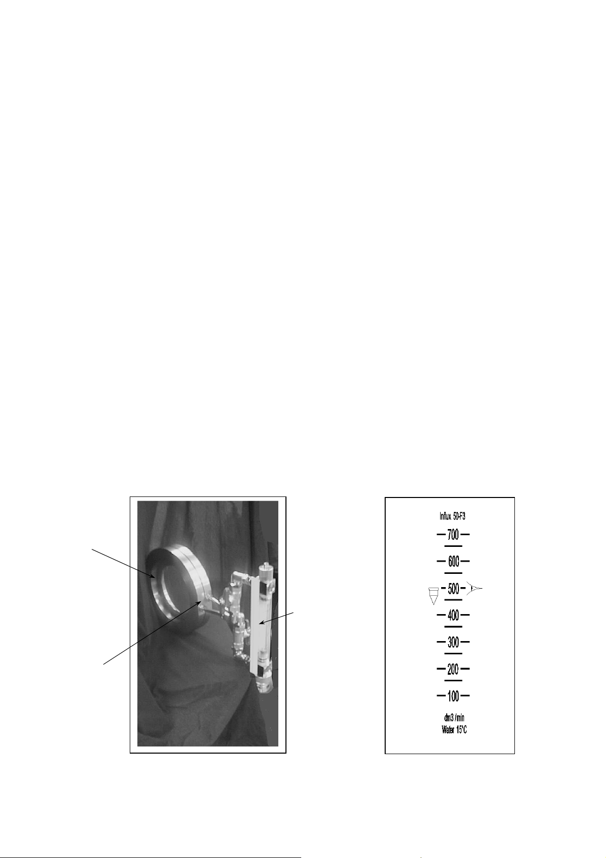
1.3 Principle of Operation
Water flow through the main orifice, creates a pressure difference between the two pressure tapping ports. These
pressure ports are connected across the bypass flow indicator, causing a small bypass flow through the indicator,
directly related to the flow through the main orifice. An indicating float positioned within the glass tube can be
read against scale markings, which show the flow rate delivery of the installation.
Main Orifice
Carrier
Pressure
Tapping Ports
Bypass Flow
Indicator

IOM FS Iss 9; April 2012; ECR1269 Page 3 of 8
2 Installation
2.1 Pipe Line Configuration
464a/01, 464a/06 F3/1, F3/6 50 250 BS1387
464a/02, 464a/07 F3/2, F3/7 80 400 BS1387
464a/03, 464a/08 F3/3, F38 100 500 BS1387
464a/04, 464a/09 F3/4, F3/9 150 750 BS1387
464a/05, 464a/10 F3/5, F3/10 200 1000 BS3600
LPCB Ref. No. Type Nom. Size mm A mm Pipe Spec.
Recommended pipeline configuration for automatic sprinkler installation of Firesure Flowmeter.
40mm
A
A
90mm
Firegroove
Fireflange
From Pump
Return
Optional Full Bore
Isolation Valve
Control
Valve
Sizes 50-150 Size 200
100mm
Firegroove

IOM FS Iss 9; April 2012; ECR1269 Page 4 of 8
2.2 Main Orifice Carrier Preparation
a) For Horizontal Pipe Work Mounting – Connect joggled connection pipes as shown
or
b) For Vertical Pipe Work Mounting – Connect joggled connection pipes as shown
c) Rotate Pipes to Position Shown in a) or b)
Check pipes for horizontal alignment.
Ensure that the pipes spacing matches the rear bypass indicator connections.
Tighten pressure tapping nuts.
Flow Direction
Up
Flow
Direction
Left to
Right
Flow
Direction
Right to Left
Flow Direction
Down
White
Red
White
Red
White
White
Red
Red
Tighten

IOM FS Iss 9; April 2012; ECR1269 Page 5 of 8
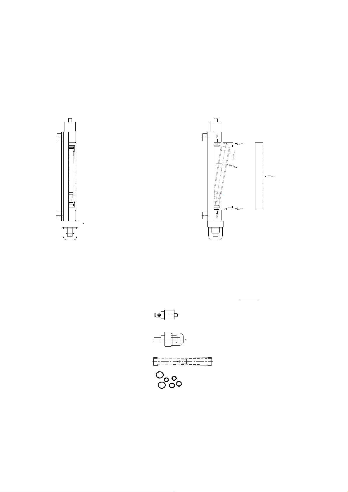
2.3 Connecting the Bypass Indicator
Rear view of indicator piping as
supplied suitable for connection to
main orifice carrier for horizontal
flow right to left or vertical flow
upward.
Rear view of indicator adjusted and
suitable for connection to main
orifice carrier for horizontal flow left
to right or vertical flow downwards.
To adjust loosen nuts, rotate arms to
position shown and retighten nuts.
Connect Bypass unit to main orifice
carrier ensuring that ‘white’ marked
pressure point connects with ‘white’
handled tap and ‘red’ pressure point
connects with ‘red’ handled tap.
Tighten connecting nuts, keeping
indicator vertical.
Remove red plastic stop and
retaining rod from top block.
Remove retaining screw and
assemble restrictor and bleed
assembly to indicator top block
with retaining screw in place.
White
Red
White
Red
nut

IOM FS Iss 9; April 2012; ECR1269 Page 6 of 8
2.4 Installation In-Line
a) Ensure direction arrow is consistent with viewed direction of flow and position Fireflange between pipeline
flanges concentrically. Concentricity can be achieved by ensuring the carrier outside diameter is central to
the fixing bolts.
b) Firegroove type should be fitted with approved couplings suitable for groove cut joints.
c) When fitting Fireflange type, ensure that any sealing gaskets do not obstruct the pipe line or carrier bore.
Size/model Min ID Gasket Permissible
50 53mm
80 79mm
100 103mm
150 155mm
200 204mm
Red
White

IOM FS Iss 9; April 2012; ECR1269 Page 7 of 8
3 Operation
3.1 Flow Test Ranges
The Firesure flowmeter is designed to test that the automatic sprinkler installation meets the required flow rate
needs. Each size of flowmeter meets a particular duty as shown below.
Size Flow Range
50 150-700
80 300-1600
100 500-3500
150 900-7900
200 2000-15000
3.2 Flow Testing and Reading
3.3 Fault Checking
Observation Possible Causes Remedy
No Flow Indication. Bypass taps closed.
Restrictor clogged.
Connections reversed to flow.
Open Taps.
Press & release restrictor button or
remove and visually check
restrictor.
Check procedure.
Flow Indication Low. Restrictor clogged.
Filter heavily clogged.
Air trapped in bypass.
Orifice carrier reverse installed
As above.
Remove and clean filter.
Bleed air from bypass.
Check flow direction against
carrier label arrow.
Open
1. With bypass taps in closed position direct flow through
meter pipe line.
2. Open bypass indicator taps.
3. Bleed air from bypass by opening bleed assembly one
revolution.
4. Close bleed assembly when air is bled.
5. Press restrictor button full home and release.
6. Flow rate is shown by aligning the top of the float with scale
markings. Test flows are highlighted on the scale.
7. When test is completed, close bypass taps and drain by
opening drain assembly and bleed assembly one turn.
8. Visually check filter bowl. If dirty, remove by unscrewing
fully and clean filter element.
9. After draining close filter and bleed assemblies.
Closed
Open
Closed
Filter and Drain Assembly
Red Tap
White
Tap
6
IOM FS Iss 9; April 2012; ECR1269 Page 8 of 8
4 Maintenance
4.1 Changing Glass Indicator
In case of breakage a glass tube indicator would be required. Refer first to the black printed Firesure model
number F3/- on the carrier label or tube before ordering a replacement.
NOTE: This model uses BLACK scaled tubes. These should not be replaced with RED scaled tubes which are
used for the extended indicator model (Firesure X).
4.2 Recommended Spares
If the installation and operating procedures are followed there should be no need for maintenance. In the event of
accidental damage or loss the following spare parts are available:
Restrictor and bleed assembly
Filter element and drain
Glass Tube Indicator
Seals Kit
Part No.
S1000
S1001
F3/-
S1002
3
2
4
5
1
2
3
1. Remove Cover
2. Remove Wedges
3. Push inserts back into end
blocks
4. Tilt glass out of backplate
5. Assembly is in reverse
order.
This manual suits for next models
1
Table of contents


