INFLUX MEASUREMENTS SprinklerSense FTI Owner's manual
IOM FTI Iss.1 October 2018 Page 1 of 8
1A Bennett House, The Dean, Alresford, Hampshire, UK. SO24 9BQ
Tel: +44 (0)1962 736736 Fax: +44 (0)1962 736737 Email: sales@influxmeasurements.com
A GUIDE TO THE INSTALLATION, OPERATION & MAINTENANCE OF
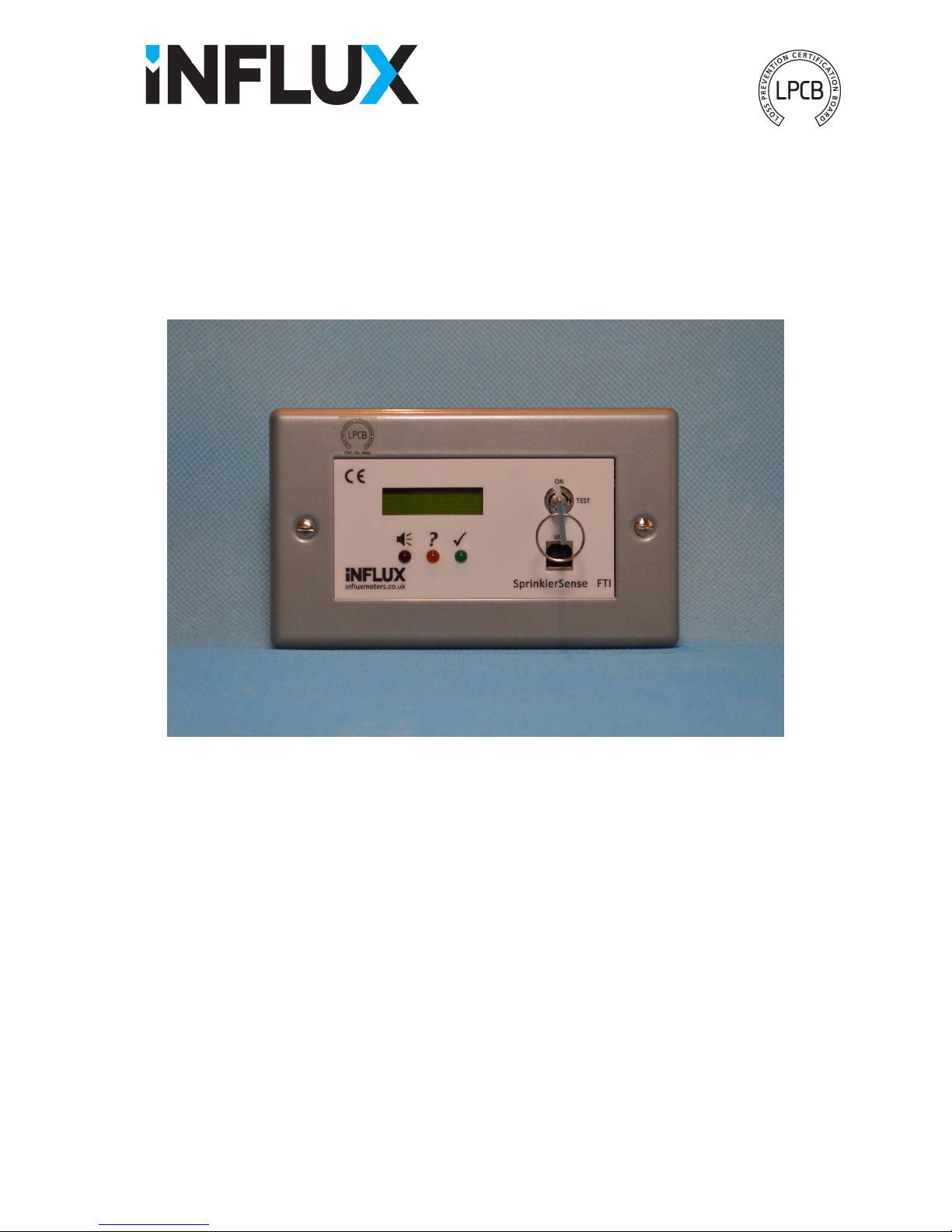
SprinklerSense Fixed Test Interface Unit, FTI
FOR USE WITH SPDB30 & SPDB90 TYPE FLOW SWITCHES
Contents: Page
1Specification & Operation 2
1.1 Introduction 2
1.2 Construction & Specification 2
1.3 Operation 2
1.4 PC Connection via USB 4
2Installation 5
2.1 Mechanical 5
2.2 Electrical & Power Supply 6
3Maintenance 8
MEASUREMENTS LTD
Cert. No. 464b

IOM FTI Iss.1 October 2018 Page 2 of 8
1 Specification & Operation
1.1 Introduction
The SprinklerSense FTI is designed specifically for use with Influx SPDB30 and SPDB90 type LPCB approved
flow switches. The unit is permanently wall mounted at an easily accessible height to provide a user interface to
access the self-test features of the flow switch and provide repeat relay contacts for both the Flow and Error
outputs.
Three LEDs are provided to indicate the current status of the flow switch, with a selectable buzzer which will
sound if an error or flow alarm is initiated. The integral display can then be used to show which error type has
been detected.
If there are no errors detected, Fire Safety personnel can use the key switch to start a flow switch check which
will test the function of the flow switch electronics and activate the Flow output. The function of the output
relay, site wiring, panel input and other devices that may be connected to the output can then be checked.
A PC app. can be used which allows further interrogation of the flow switch via a USB connection.
1.2 Construction & Specification
Housing: 2 Gang Faceplate (surface mounting rear box provided)
Operating Temperature Range: 2 to 68C
Supply Voltage: 9 to 30V D.C.
Quiescent Current (maximum) 170mA @ 12V, 100mA @ 24V (includes flow switch and FTI)
Quiescent Current (average) 90mA @ 12V, 65mA @ 24V (includes flow switch and FTI)
Flow Switch Repeat Output: 1x SPCO Relay, 24V D.C., 500mA
Error Repeat Output: 1x SPCO Relay, 24V D.C., 500mA
1.3 Operation
The FTI is connected to the SprinklerSense flow switch via a serial communications link (wired). It continuously
requests status information from the sensor and reacts accordingly. In normal use, without flow or errors, the
green LED will flash slowly to indicate that the flow switch is functioning OK. If a sprinkler flow rate is
detected the red LED will flash quickly and if enabled the buzzer will sound. If an error is detected the yellow
LED will flash at a medium rate and the buzzer will sound (if enabled). For flow and error states, the appropriate
output relay will also switch.
System Errors
While the yellow LED is flashing, personnel with access to the key for the switch can if required, turn the key to
the TEST position which will allow the error type to be displayed. This action will also silence the buzzer for a
period of 2 hours. If the key is left in this position, the unit will timeout. The key will then have to be turned
back to ON before the display can be reactivated.
An error condition will be activated in the event of one of the following:
1) A fault is detected with one or more of the sensor probes.
2) A calibration error is detected outside of factory tolerances.
3) The SPDB30/90 flow switch is not responding.
Note: For Power supply failure detection the Error output from the SPDB30/90 should be used.
The following conditions will also cause an error condition if enabled:
1) The sensor cannot detect water in the pipe, Dry Pipe (enabled by default).
2) A temperature of less than 2°C is detected in the pipe, Freeze Risk (enabled by default).
3) A small but continuous flow is detected, Leak Flow (dis-enabled by default).
Note: Settings are stored in the flow switch.

IOM FTI Iss.1 October 2018 Page 3 of 8
Flow Switch Check
While the green LED is flashing, turning the key to TEST will start a flow switch check. This should only be
carried out by or with the permission of Fire Safety personnel, after the main panel has been set ready for the
test. Failure to carry out this procedure in the correct order could result in a false alarm condition. If the key is
left in this position, the unit will timeout back to its normal ON mode. To start a test if the key has been left in
the TEST position and timed out, the key must be returned to ON position and then re-set to TEST.
Flow Switch Test Procedure:
Authorise
•Gain permission from Fire Safety personnel
•Set main panel ready for test, to avoid alarm sounding
Test
•Turn key to 'TEST' position
•Wait for flowswitch set delay period
CHECK!
•Ensure that red LED starts to flash
•Check that a flow alarm signal is indicated by main panel
Reset
•Return key to 'ON' position
•Wait a few seconds for the Green light to flash
•Return the main panel to normal condition

IOM FTI Iss.1 October 2018 Page 4 of 8
1.4 PC Connection via USB
If a PC with the SprinklerSense PTE application installed is connected via a USB lead, the key must be turned to
TEST to enable the connection. This should only be enabled after the PC is on and connected, and the FTI
display shows “USB OK”. It is good practice to return the key to the ON position before disconnecting the USB
or shutting down the PC. Failure to carry out this procedure in the correct order could result in a false alarm
condition. While connected to a PC the key position will not timeout.
USB Connection Procedure:
For SprinklerSense PTE installation, refer to the software installation guide. If the software is installed but
‘USB OK’ is not displayed when expected, it is likely that the PC has not yet recognised that the device is
connected. This can be checked using the Device Manager which can be found via Control Panel and then
System on the PC. The device should appear as a COM port in the list. The list can be refreshed by right clicking
on the top level text and selecting ‘Scan for hardware changes’.
Setup
•Ensure FTI is powered up with key in 'ON' position
•Turn on PC with previously installed software
Connect
•FIRST, plug in USB lead to connect PC and FTI
CHECK!
•Ensure that display shows 'USB OK'
•Turn key to 'TEST' position
•Run SprinklerSense PTE application
Disconnect
•When finished, exit application
•Return key to 'ON' position
•Finally, disconnect the USB lead

IOM FTI Iss.1 October 2018 Page 5 of 8
2 Installation
2.1 Mechanical
The 2 Gang size fascia plate is supplied with a matching surface mounted box. If required an alternative 2 Gang
type box can be used with a minimum depth of 35mm. The box should be mounted in an easily accessible
position where it is not likely to become wet in normal use.
Cable entries should be made available for cables; 1) from the power supply, 2) to the flow switch, 3) from the
relay outputs, if required and 4) from a remote key-switch activation connection, if required.
The box should be fixed using suitable fixings, not supplied.
Table of contents


