inforce 6720 User manual

Confidential and Proprietary –Inforce Computing Inc.
NO PUBLIC DISCLOSURE PERMITTED: Please report postings of this document on public servers
Restricted Distribution: Not to be distributed to anyone who is not an employee of either
Inforce Computing or its subsidiaries without the express approval of Inforce Computing.
Not to be used, copied, reproduced, or modified in whole or in part, nor its contents revealed in
any manner to others without the express written permission of Inforce Computing, Inc.
Inforce Computing is a trademark of Inforce Computing Incorporated, registered in the United
States and other countries. All Inforce Computing Incorporated trademarks are used with
permission. Other product and brand names may be trademarks or registered trademarks of their
respective owners.
This technical data may be subject to U.S. and international export, re-export, or transfer (“export”)
laws. Diversion contrary to U.S. and international law is strictly prohibited.
Inforce Computing Inc.
48820 Kato Road, # 600B
Fremont, CA 94538
U.S.A.
© 2021 Inforce Computing Inc.
Inforce 6720™
User Guide
003767 Rev A
May 13, 2021
Submit technical questions at:
http://www.inforcecomputing.com/techweb/
Inforce 6720™User Guide Revision History
003767 Rev A MAY CONTAIN U.S. AND INTERNATIONAL EXPORT CONTROLLED INFORMATION i
Confidential and Proprietary –Inforce Computing, Inc.
Provided under NDA
Revision History
Revision
Date
Description
Author
A
13 May 2021
Initial Release
GU
Approval Record
Function
Name
Date
Reviewed By
SS/DD
13 May 2021
Approved By
PSD
13 May 2021

Inforce 6720™User Guide License Agreement
003767 Rev A MAY CONTAIN U.S. AND INTERNATIONAL EXPORT CONTROLLED INFORMATION ii
Confidential and Proprietary –Inforce Computing, Inc.
Provided under NDA
License Agreement
Your use of this document is subject to and governed by those terms and conditions in the Inforce
Computing Purchase and Software License Agreement for the SDA845 based Inforce 6720, which you or
the legal entity you represent, as the case may be, accepted and agreed to when purchasing a Inforce 6720
from Inforce Computing Inc. (“Agreement”). You may use this document, which shall be considered part of
the defined term “Documentation” for purposes of the Agreement, solely in support of your permitted use
of the Inforce 6720 under the Agreement. Distribution of this document is strictly prohibited without the
express written permission of Inforce Computing Inc. and its respective licensors, which they can withhold,
condition or delay in its sole discretion.
Qualcomm is a trademark of Qualcomm Inc, registered in the United States and other countries. Other
product and brand names used herein may be trademarks or registered trademarks of their respective
owners.
This document contains technical data that may be subject to U.S. and international export, re-export, or
transfer (“export”) laws. Diversion contrary to U.S. and international law is strictly prohibited.

Inforce 6720™User Guide Preface
003767 Rev A MAY CONTAIN U.S. AND INTERNATIONAL EXPORT CONTROLLED INFORMATION iii
Confidential and Proprietary –Inforce Computing, Inc.
Provided under NDA
Preface
This User Guide familiarizes the end user with the specification, interfaces, setup, and usage of the Inforce
6720.
Intended Audience
This User Guide is intended for technically qualified personnel. It is not intended for general audiences.
Document Organization
The chapters in this document are arranged as follows:
1. Scope
2. Hardware Specifications
3. System Setup and Usage
4. Compliance Information
5. Contact Information
Conventions
The following conventions are used in this document:
CAUTION
Caution warns the user about how to prevent damage to hardware or loss of data.
NOTE
Note calls attention to important information.
References
1. Inforce_6720_Hardware_Reference_Manual_003768
Note
This document is subject to change without notice.
Support Information
Every effort has been made to ensure the accuracy of the User Guide. If you have any comments, questions,
or ideas regarding this document, contact Inforce’s technical support at:
techsupport@inforcecomputing.com

Inforce 6720™User Guide Terminology
003767 Rev A MAY CONTAIN U.S. AND INTERNATIONAL EXPORT CONTROLLED INFORMATION iv
Confidential and Proprietary –Inforce Computing, Inc.
Provided under NDA
Terminology
The table below gives descriptions to some common terms used in the User Guide.
Term
Description
ADB
Android Debug Bridge
BT
Bluetooth
CSI
Camera Serial Interface
DDR
Double Data Rate
DSI
Display Serial Interface
HDMI
High-Definition Multimedia Interface
LED
Light-Emitting Diode
LPDDR
Low Power DDR
NC
Not Connected
PC
Personal Computer
PCB
Printed Circuit Board
RF
Radio Frequency
SBC
Single Board Computer
SD
Secure Digital
SoC
System On Chip
SSD
Solid State Drive
UART
Universal Asynchronous Receiver Transmitter
UFS
Universal Flash Storage
USB
Universal Serial Bus

Inforce 6720™User Guide Table of Contents
003767 Rev A MAY CONTAIN U.S. AND INTERNATIONAL EXPORT CONTROLLED INFORMATION v
Confidential and Proprietary –Inforce Computing, Inc.
Provided under NDA
Table of Contents
1. SCOPE...................................................................................................................................................1
2. HARDWARE SPECIFICATIONS............................................................................................................2
2.1 INTRODUCTION .......................................................................................................................................................................2
2.2 ARCHITECTURE.........................................................................................................................................................................2
2.3 SYSTEM SPECIFICATIONS.....................................................................................................................................................3
2.4 ELECTRICAL CHARACTERISTICS.........................................................................................................................................3
2.5 USER INTERFACES ...................................................................................................................................................................4
3. SYSTEM SETUP AND USAGE ..............................................................................................................6
3.1 SWITCHES...................................................................................................................................................................................6
3.2 LED INDICATIONS ...................................................................................................................................................................6
3.3 WI-FI/BT ANTENNA ................................................................................................................................................................7
3.4 INTERFACES ...............................................................................................................................................................................8
3.5 STEPS TO BOOT INFORCE 6720.........................................................................................................................................8
3.6 FASTBOOT MODE....................................................................................................................................................................9
4. COMPLIANCE INFORMATION..........................................................................................................10
4.1 CLASS B PRODUCT COMPLIANCE STATEMENT....................................................................................................... 10
4.2 COMPLIANCE STATEMENT............................................................................................................................................... 10
4.3 FCC RADIATION EXPOSURE STATEMENT................................................................................................................... 10
5. CONTACT INFORMATION ................................................................................................................11

Inforce 6720™User Guide Table of Figures
003767 Rev A MAY CONTAIN U.S. AND INTERNATIONAL EXPORT CONTROLLED INFORMATION vi
Confidential and Proprietary –Inforce Computing, Inc.
Provided under NDA
Table of Figures
Figure 1: Block Diagram.....................................................................................................................................................................2
Figure 2: Inforce 6720 Interfaces....................................................................................................................................................4
Figure 3: Switches on IO Panel........................................................................................................................................................6
Figure 4: LEDs on IO Panel................................................................................................................................................................6
Figure 5: Wi-Fi/BT Antennae on SMA Connectors..................................................................................................................7

Inforce 6720™User Guide Table of Tables
003767 Rev A MAY CONTAIN U.S. AND INTERNATIONAL EXPORT CONTROLLED INFORMATION vii
Confidential and Proprietary –Inforce Computing, Inc.
Provided under NDA
Table of Tables
Table 1: Inforce 6720 Specifications .............................................................................................................................................3
Table 2: Inforce 6720 Interfaces......................................................................................................................................................5
Table 3: Switch Functions..................................................................................................................................................................6
Table 4: LED Indications.....................................................................................................................................................................6
Table 5: Antenna Details....................................................................................................................................................................7
Table 6: Interface Functions .............................................................................................................................................................8

Inforce 6720™User Guide Scope
003767 Rev A MAY CONTAIN U.S. AND INTERNATIONAL EXPORT CONTROLLED INFORMATION 1
Confidential and Proprietary –Inforce Computing, Inc.
Provided under NDA
1. SCOPE
This document describes the system setup and usage of Qualcomm Snapdragon 845 (SDA845) processor
based Inforce 6720.
Hardware Identification Labels
Label are present on the Inforce 6720. The following information is conveyed on the product:
◼Serial Number for Inforce 6720
◼WIFI & BT MAC address
◼Ethernet MAC address

Inforce 6720™User Guide Hardware Specifications
003767 Rev A MAY CONTAIN U.S. AND INTERNATIONAL EXPORT CONTROLLED INFORMATION 2
Confidential and Proprietary –Inforce Computing, Inc.
Provided under NDA
2. HARDWARE SPECIFICATIONS
2.1 INTRODUCTION
The Inforce 6720 is an Application Ready Platform, based on Qualcomm’s 64-bit Snapdragon™ 845
processor (SDA845 SoC) with a low profile enclosure. Inforce 6720 can be used to develop, test, and deploy
product solutions around Qualcomm Snapdragon 845 (SDA845) processor.
2.2 ARCHITECTURE
The functional diagram of Inforce 6720 is shown below.
Figure 1: Block Diagram

Inforce 6720™User Guide Hardware Specifications
003767 Rev A MAY CONTAIN U.S. AND INTERNATIONAL EXPORT CONTROLLED INFORMATION 3
Confidential and Proprietary –Inforce Computing, Inc.
Provided under NDA
2.3 SYSTEM SPECIFICATIONS
The following table shows the hardware specification of Inforce 6720.
Table 1: Inforce 6720 Specifications
Processor
Processor
Qualcomm® SDA845 SoC
Memory
Main Memory and
Storage
4GB LPDDR4x 1866Mhz
64GB UFS 2.1
IO Interfaces
Interfaces
1× USB v3.0 Type-A, 1× USB v3.0 Type-C (Debug), 1× 4K HDMI Out, 1x 4K HDMI In, 1× microSD
socket, 1× Combo audio jack, 2× SMA (Wi-Fi/BT), 1× SMA (GPS), 1× Ethernet jack (POE+)
Internal Interfaces
1× M.2 SATA SSD slot, 1× UART (Debug) 3-pin header
LED Indications
1x Power indication, 2x Board status indication, 3x User configurable LEDs
Misc.
5x Boot configuration switches
Form Factor
Mechanical
175mm × 160mm x 25mm
Power
Power Input
12V/3A DC Adapter, POE+ Injector
Others
Temperature
Specifications
Operating Temperature: 0°C to 50°C
Software
Operating System
Android
2.4 ELECTRICAL CHARACTERISTICS
Power Supplies:
Inforce 6720 can be operated from the following power source:
◼12V/3A DC Jack
◼POE+ Injector
NOTE
Both 12V DC Jack and POE+ injector can be connected simultaneously.

Inforce 6720™User Guide Hardware Specifications
003767 Rev A MAY CONTAIN U.S. AND INTERNATIONAL EXPORT CONTROLLED INFORMATION 4
Confidential and Proprietary –Inforce Computing, Inc.
Provided under NDA
2.5 USER INTERFACES
The following figure shows the interfaces on the Inforce 6720.
Figure 2: Inforce 6720 Interfaces
CAUTION
Inforce 6720 has a thin PCB, handle with care while using the ports.
2
3
1
5
1
6
1
7
1
8
9
10
11
12
13
14
1
4
1
Inforce 6720™User Guide Hardware Specifications
003767 Rev A MAY CONTAIN U.S. AND INTERNATIONAL EXPORT CONTROLLED INFORMATION 5
Confidential and Proprietary –Inforce Computing, Inc.
Provided under NDA
Table 2: Inforce 6720 Interfaces
Sl.
No.
Description
1
GPS SMA Female Receptacle
2
WIFI/BT SMA Female Receptacle
3
4x LEDs
4
Headphone Jack
5
USB 3.0 Type A Port
6
MicroSD Card Slot
7
WIFI/BT SMA Female Receptacle
8
RJ45 Ethernet Jack
9
12V DC Jack
10
Power ON Switch
11
Reset\Vol+ Switch
12
4K HDMI Input
13
4K HDMI Output
14
USB-C Port for Display and Debug

Inforce 6720™User Guide System Setup and Usage
003767 Rev A MAY CONTAIN U.S. AND INTERNATIONAL EXPORT CONTROLLED INFORMATION 6
Confidential and Proprietary –Inforce Computing, Inc.
Provided under NDA
3. SYSTEM SETUP AND USAGE
3.1 SWITCHES
Following are the switches and functions on the Inforce 6720.
Table 3: Switch Functions
Switch
Function
Comments
Power
Power ON
oPress to boot-up
oOnce booted up press to Sleep
oWhile in Sleep press to Wake up
oPress and hold for power menu
Reset
Reset\Vol +
oVolume+ control
oOptional factory reset
Figure 3: Switches on IO Panel
3.2 LED INDICATIONS
Following are the LEDs and indications on the Inforce 6720.
Figure 4: LEDs on IO Panel
Table 4: LED Indications
Reference
Function
Comments
PWR
Power Status
12V Power Status
LED1
Notify LED1
User programmable
LED2
Notify LED2
User programmable
LED3
Notify LED3
User programmable
PWR
Power
LED1
LED2
LED3
Reset
Inforce 6720™User Guide System Setup and Usage
003767 Rev A MAY CONTAIN U.S. AND INTERNATIONAL EXPORT CONTROLLED INFORMATION 7
Confidential and Proprietary –Inforce Computing, Inc.
Provided under NDA
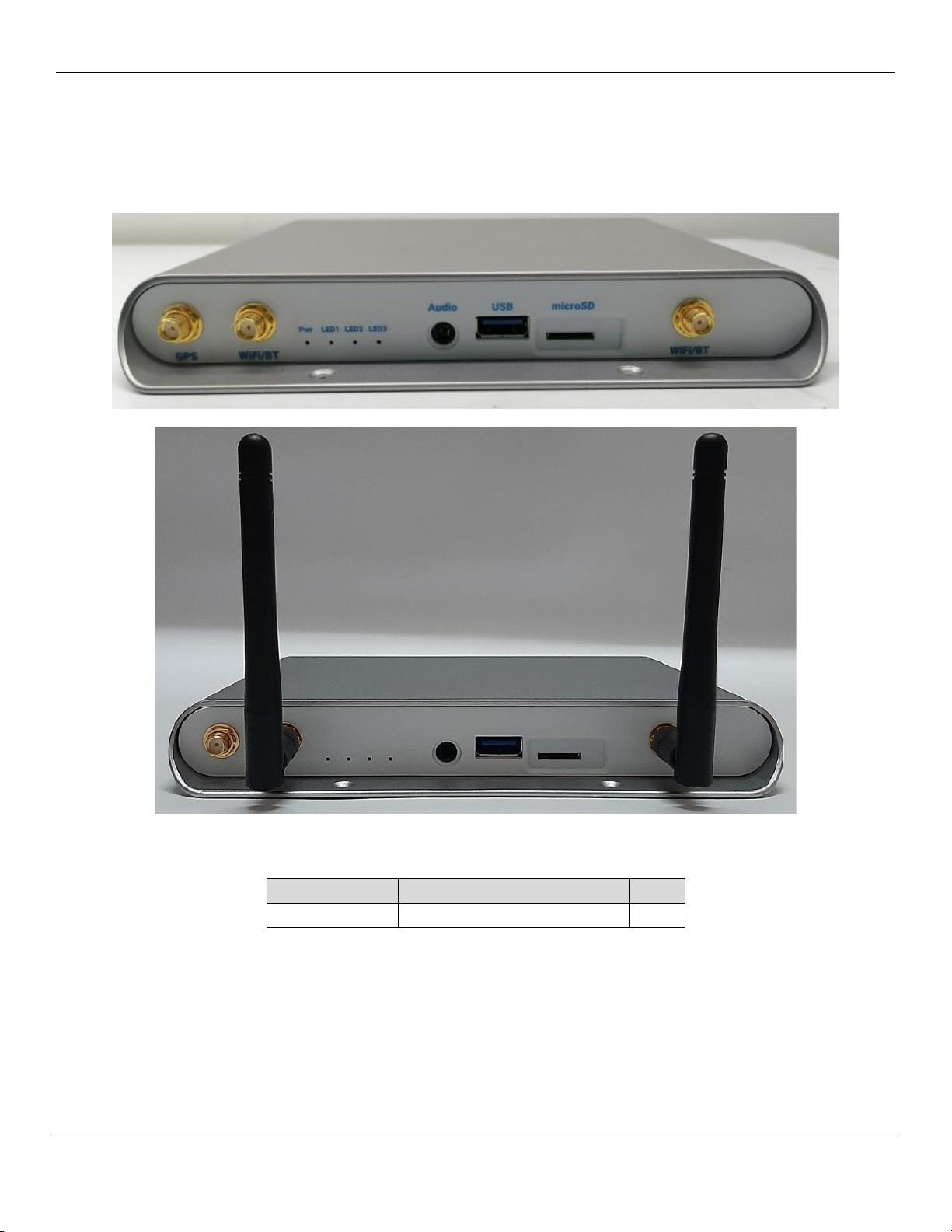
3.3 WI-FI/BT ANTENNA
Fasten the Wi-Fi/BT Antennae on to the SMA connectors on the IO panel as shown in below figure.
Figure 5: Wi-Fi/BT Antennae on SMA Connectors
Table 5: Antenna Details
Manufacturer
Manufacturer Part Number
Qty
Molex
2128600001
2
Inforce 6720™User Guide System Setup and Usage
003767 Rev A MAY CONTAIN U.S. AND INTERNATIONAL EXPORT CONTROLLED INFORMATION 8
Confidential and Proprietary –Inforce Computing, Inc.
Provided under NDA
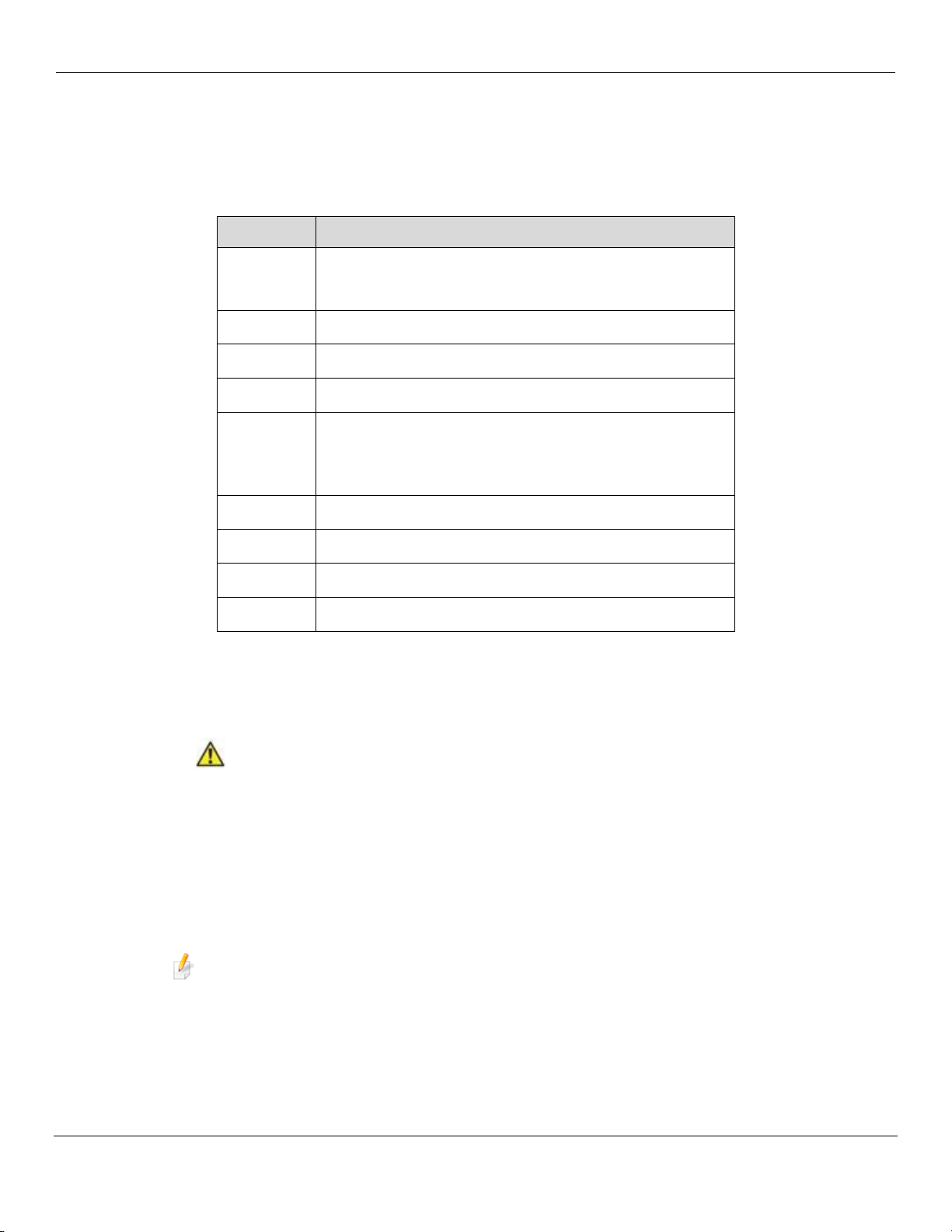
3.4 INTERFACES
Following are the interfaces on the Inforce 6720.
Table 6: Interface Functions
Interface
Comments
Ethernet
oConnect directly to LAN port for Ethernet access
oConnect to a POE+ Injector or POE+ capable switch for
Ethernet access and Power input
12V DC
oConnect Power Adaptor DC plug for Power input
HDMI In
oConnect HDMI source using HDMI cable
HDMI Out
oConnect to Monitor using HDMI cable for Display
USB-C
oConnect to PC using USB-C to USB Type-A cable for
ADB debug access
oConnect to Monitor using USB-C to DisplayPort cable
for Display
GPS
oConnect SMA Male Plug GPS Antenna
Audio
oConnect Headphone with MIC for audio
USB
oConnect USB Type-A compatible devices e.g., mouse
microSD
oInsert microSD card for data access
3.5 STEPS TO BOOT INFORCE 6720
1. Connect the DC power adaptor or POE Injector to the Inforce 6720.
CAUTION
Use only the DC power adaptor provided by Inforce Computing.
2. Connect the HDMI Out to a compatible Monitor using an HDMI cable.
3. Switch ON the DC adaptor or POE+ Injector.
4. Press the Power button to boot up.
5. Display will come up on the HDMI monitor once Inforce 6720 boots up.
NOTE
First time booting might take longer time than normal booting.
Inforce 6720™User Guide System Setup and Usage
003767 Rev A MAY CONTAIN U.S. AND INTERNATIONAL EXPORT CONTROLLED INFORMATION 9
Confidential and Proprietary –Inforce Computing, Inc.
Provided under NDA
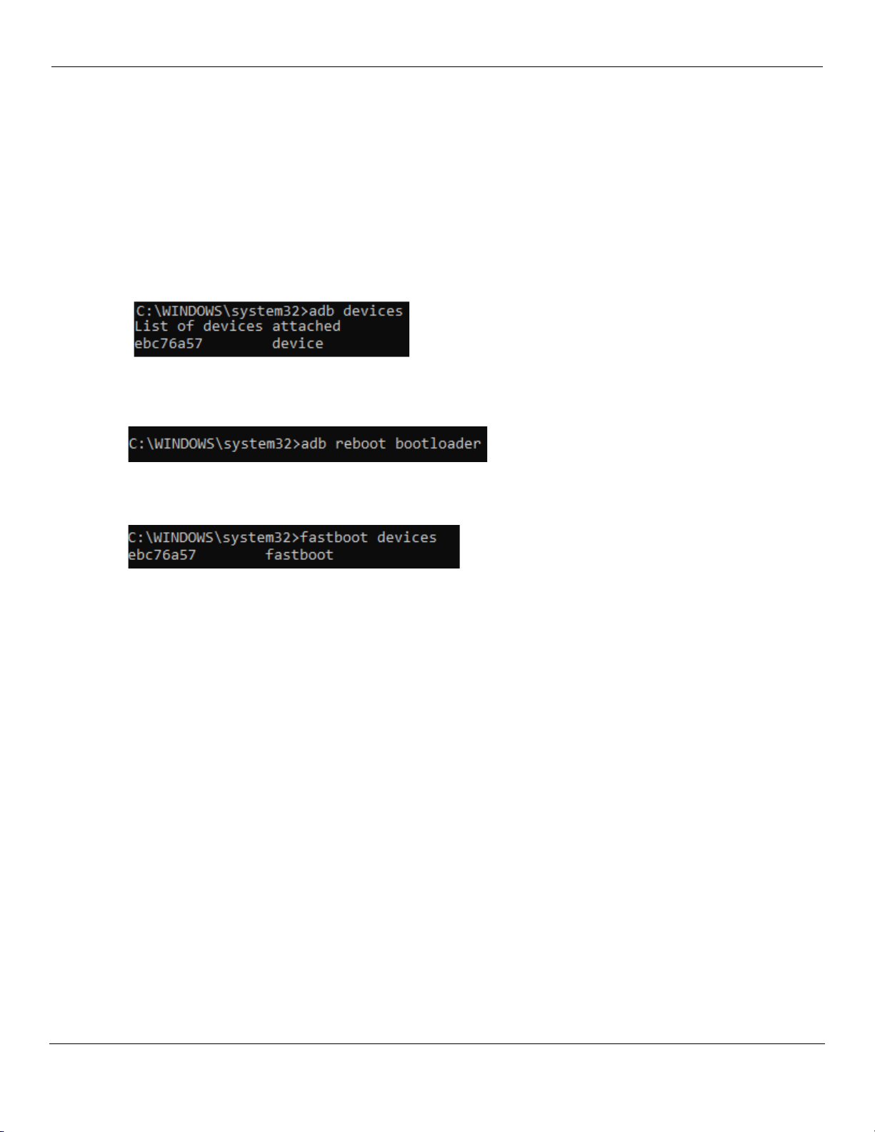
3.6 FASTBOOT MODE
Follow the below steps to enter fastboot mode:
1. Power ON and boot up the Inforce 6720
2. Connect the USB-C port of 6720 to host PC using a USB Type-C to Type-A cable
3. Once the 6720 is booted up, open the command prompt in the PC and enter the following
command
•adb devices
4. Once ADB device is listed, enter bootloader using following command
•adb reboot bootloader
5. To confirm if the device has entered fastboot mode, use below command
•fastboot devices

Inforce 6720™User Guide Compliance Information
003767 Rev A MAY CONTAIN U.S. AND INTERNATIONAL EXPORT CONTROLLED INFORMATION 10
Confidential and Proprietary –Inforce Computing, Inc.
Provided under NDA
4. COMPLIANCE INFORMATION
4.1 CLASS B PRODUCT COMPLIANCE STATEMENT
Note: This equipment has been tested and found to comply with the limits for a Class B digital device,
pursuant to part 15 of the FCC Rules. These limits are designed to provide reasonable protection against
harmful interference in a residential installation. This equipment generates, uses and can radiate radio
frequency energy and, if not installed and used in accordance with the instructions, may cause harmful
interference to radio communications. However, there is no guarantee that interference will not occur in a
particular installation. If this equipment does cause harmful interference to radio or television reception,
which can be determined by turning the equipment off and on, the user is encouraged to try to correct the
interference by one or more of the following measures:
•Reorient or relocate the receiving antenna.
•Increase the separation between the equipment and receiver.
•Connect the equipment into an outlet on a circuit different from that to which the receiver is
connected.
•Consult the dealer or an experienced radio/TV technician for help.
4.2 COMPLIANCE STATEMENT
1) The Inforce 6720 is in compliance with the essential requirements and other relevant provisions of
the RE Directive 2014/53/EU.
2) This device is restricted to indoor use only when operating in the 5150 to 5350 MHz frequency
range.
3) A minimum separation distance 20cm is required.
4.3 FCC RADIATION EXPOSURE STATEMENT
This equipment complies with FCC radiation exposure limits set forth for an uncontrolled environment. This
equipment should be installed and operated with minimum distance 20cm between the radiator & your
body.

Inforce 6720™User Guide Contact Information
003767 Rev A MAY CONTAIN U.S. AND INTERNATIONAL EXPORT CONTROLLED INFORMATION 11
Confidential and Proprietary –Inforce Computing, Inc.
Provided under NDA
5. CONTACT INFORMATION
USA (Corporate Headquarters)
Inforce Computing Inc.
48820 Kato Road, # 600B
Fremont, California 94538 USA.
Phone: +1 510 683 9999
Fax: +1 510 683 9909
For technical assistance refer:
http://www.inforcecomputing.com/techweb
For technical support contact:
techsupport@inforcecomputing.com
For sales contact:
sales@inforcecomputing.com
Table of contents


