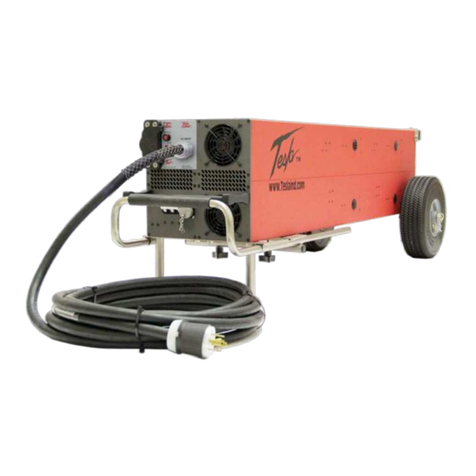
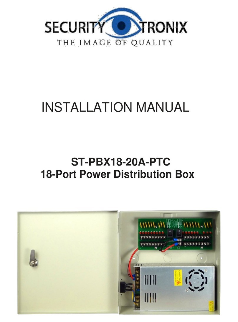
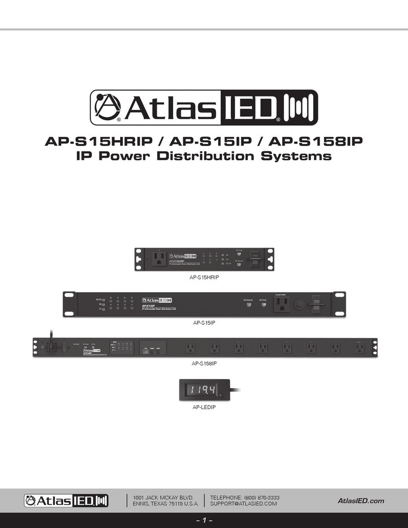
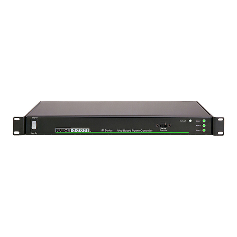
Infrapower PPS-02-S User manual

www.austin-hughes.comUM-PPS-02-S-Q421V1
PPS-02-S, IP dongle GUI & SNMP
InfraPower Intelligent PDU
Inspired by Your Data Center
User Manual
Designed and manufactured by Austin Hughes
1-Phase 1-Phase
Dual Feed 3-Phase

www.austin-hughes.comUM-PPS-02-S-Q421V1
Legal Information
First English printing, December 2021
Information in this document has been carefully checked for accuracy; however, no guarantee is given to the correctness
of the contents. The information in this document is subject to change without notice. We are not liable for any injury or
loss that results from the use of this equipment.
Safety Instructions
Please read all of these instructions carefully before you use the device. Save this manual for
future reference.
■Unplug equipment before cleaning. Don’t use liquid or spray detergent; use a moist cloth.
■Keep equipment away from excessive humidity and heat. Preferably, keep it in an air-conditioned environment with
temperatures not exceeding 40º Celsius (104º Fahrenheit).
■When installing, place the equipment on a sturdy, level surface to prevent it from accidentally falling and causing dam
age to other equipment or injury to persons nearby.
■When the equipment is in an open position, do not cover, block or in any way obstruct the gap between it and the
power supply. Proper air convection is necessary to keep it from overheating.
■Arrange the equipment’s power cord in such a way that others won’t trip or fall over it.
■If you are using a power cord that didn’t ship with the equipment, ensure that it is rated for the voltage and current
labelled on the equipment’s electrical ratings label. The voltage rating on the cord should be higher than the one listed
on the equipment’s ratings label.
■Observe all precautions and warnings attached to the equipment.
■If you don’t intend on using the equipment for a long time, disconnect it from the power outlet to prevent being dam
aged by transient over-voltage.
■Keep all liquids away from the equipment to minimize the risk of accidental spillage. Liquid spilled on to the power
supply or on other hardware may cause damage, fire or electrical shock.
■Only qualified service personnel should open the chassis. Opening it yourself could damage the equipment and invali
date its warranty.
■If any part of the equipment becomes damaged or stops functioning, have it checked by qualified service personnel.
What the warranty does not cover
■Any product, on which the serial number has been defaced, modified or removed.
■Damage, deterioration or malfunction resulting from:
□Accident, misuse, neglect, fire, water, lightning, or other acts of nature, unauthorized product modification, or
failure to follow instructions supplied with the product.
□Repair or attempted repair by anyone not authorized by us.
□Any damage of the product due to shipment.
□Removal or installation of the product.
□Causes external to the product, such as electric power fluctuation or failure.
□Use of supplies or parts not meeting our specifications.
□Normal wear and tear.
□Any other causes which does not relate to a product defect.
■Removal, installation, and set-up service charges.
Regulatory Notices Federal Communications Commission (FCC)
This equipment has been tested and found to comply with the limits for a Class A digital device, pursuant to Part 15 of the
FCC rules. These limits are designed to provide reasonable protection against harmful interference in a residential instal-
lation.
Any changes or modifications made to this equipment may void the user’s authority to operate this equipment. This
equipment generates, uses, and can radiate radio frequency energy and, if not installed and used in accordance with the
instructions, may cause harmful interference to radio communications.
However, there is no guarantee that interference will not occur in a particular installation. If this equipment does cause
harmful interference to radio or television reception, which can be determined by turning the equipment offand on, the
user is encouraged to try to correct the interference by one or more of the following measures:
■Re-position or relocate the receiving antenna.
■Increase the separation between the equipment and receiver.
■Connect the equipment into an outlet on a circuit different from that to which the receiver is connected.

www.austin-hughes.comUM-PPS-02-S-Q421V1
Content
< 1.1 > IP Dongle GUI PPS-02-S Key Features
< 1.2 > IP Dongle Installation & Meter ( PDU ) Cascade
< 1.3 > Meter ( PDU ) Level Setting
< 1.4 > IP Dongle Configuration
< 1.5 > PPS-02-S IP Dongle GUI
< 1.6 > SNMP Setup
< 1.7 > IP Dongle Firmware Upgrade
< 1.8 > DHCP Setting
< 1.9 > Command Line Interface Access
P. 1
P. 2
P. 3
P. 4
P. 5
P. 10
P. 15
P. 17
P. 19

www.austin-hughes.comUM-PPS-02-S-Q421V1 P. 1
InfraPower Manager PPS-02-S is a FREE built-in GUI of each IP dongle ( IPD-02-S only ) to remotely monitor the con-
nected PDUs ( max. up to 16 PDU levels )
< 1.1 > IP Dongle GUI PPS-02-S Key Features
InfraPower PPS-02-S
Features
Capacity IP Dongle Group ( Just 1 for 16 PDU levels ) 1
PDU number 16
Concurrent Users 1
Enhanced
Features
Outlet Level kWh & Amp Measurement
Outlet Scheduling
Energy Consumption ( kWh ) Monitoring
Apparent Power ( kVA ) Monitoring
Power Factor Measurement
Circuit Breaker ( MCB ) Monitoring
Basic
Features
Aggregate Current ( Amp ) Monitoring
Individual Outlet Switch ON/OFF
Temp-Humid Monitoring
Alarm Threshold Setting
Rising Alert Threshold Setting
Door & Smoke Sensor Monitoring
Remote Access via Web
Graphic User Interface
PDU
Series
Support
Single & 3 Phase WMonitored PDU
Single & 3 Phase Wi Monitored PDU ( Outlet Measurement )
Single & 3 Phase WS Switched PDU
Single & 3 Phase WSi Switched PDU ( Outlet Measurement )
Single & 3 Phase Dual Feed WMonitored PDU
Single & 3 Phase Dual Feed Wi Monitored PDU ( Outlet Measurement )
Single & 3 Phase Dual Feed WS Switched PDU
Single & 3 Phase Dual Feed WSi Switched PDU ( Outlet Measurement )
Single & 3 Phase inline meter
Single & 3 Phase Dual Feed inline meter

www.austin-hughes.comUM-PPS-02-S-Q421V1 P. 2
Part no.
IPD-02-S
< 1.2 > IP Dongle Installation & Meter ( PDU ) Cascade
Vertical IP dongle installation steps :
- slide the IP dongle on the plate above the meter
- plug the RJ-45 connector of IP dongle into the LINK port of the 1st level PDU meter
- use the CAT. 5 / 6 cable to connect IP dongle to network device
IP Dongle Access to 16 PDU Levels
Patented IP Dongle provides IP remote access to the PDUs by a true network IP address chain. Only 1 x IP dongle
allows access to max. 16 PDUs in daisy chain - which is a highly efficient application for saving not only the IP re-
mote accessories cost, but also the true IP addresses required on the PDU management.
Hot-Pluggable design facilitates the IP dongle installation. Simply integrate the IP Dongle to the 1st PDU, then the
entire daisy chain group can be remote over IP. Hence, administrator can remotely access all PDUs in the daisy
chain group by one single IP via the IP Dongle.
IP Dongle for vertical PDU & 2U rackmount PDU
- SNMP capability v2 / v3
1st level
PDU meter
3rd level
PDU meter
2nd level
PDU meter
Cat 5 / 6 cable
Up to 20M
Cat 5 / 6 cable
Up to 20M
To LINK port of
the 1st PDU
IP dongle
Network Hub
To LAN port
To LINK port
of next PDU
( Up to 16 levels )
LINK OUT
TH 1 TH 2
Meter ( PDU ) Cascade
■The PDU can be cascaded up to 16 levels
■For IP PDU access simply connect 1 x IP Dongle - IPD-02-S
■1 x IP Dongle allows access to 16 levels
■Single & 3 Phase PDU can be inter-cascaded in the single daisy chain

www.austin-hughes.comUM-PPS-02-S-Q421V1 P. 3
< 1.2 > IP Dongle Installation & Meter ( PDU ) Cascade
IP Dongle for 1U rackmount PDU
- SNMP capability v2 / v3
Installation steps :
- fix the IP Dongle on the rear side of rackmount PDU with 4 screws
- plug its RJ-45 connector into the LINK port of the 1st level PDU meter
- connect IP Dongle to network device via CAT. 5 / 6 cable
Network Hub
To LAN port
Part no.
IPD-H02-S
To LINK port
of the 1st PDU
Step 3 - In display 9.1, Press the & button to select PDU level no. & press to confirm
Step 4 - Press to exit
< 1.3 > Meter ( PDU ) Level Setting
Step 1 - Press the & button to display no.9 and press to confirm
Step 2 - Press the & button to PDU ID and press to confirm
( II ) For 2.8″LCD Meter ( With touchscreen function )
( I) For 1.8″LCD Meter ( No touchscreen function )

www.austin-hughes.comUM-PPS-02-S-Q421V1 P. 4
< 1.4 > IP Dongle Configuration
Step 1. Prepare a notebook computer to download the IP setup utilities from the link :
http://www.austin-hughes.com/support/utilities/infrapower/IPdongleSetup.msi
Step 2. Double Click the IPDongleSetup.msi and follow the instruction to complete the installation
Step 3. Go to each first level PDU with the notebook computer & a piece of CAT. 5 / 6 cable to configure the
IP dongle by IP setup utilities as below. Please take the procedure for all IP dongles ONE BY ONE
After the completion of IP dongle connection, please take the following steps to configure the IP dongle :
IP dongle on 1st level PDU
To IP dongle
LAN port
To notebook computer
LAN port
CAT. 5 / 6 cable
Step 4. Click “Scan ” to search the connected IP dongle
Step 5. Enter device name in “ Name ” ( min. 4 char. / max. 16 char. ). Default is “ Name ”
Step 6. Enter device location in “ Location ” ( min. 4 char. / max. 16 char. ). Default is “ Rack_001 ”
Step 7. Enter password in “ Password ” for authentication ( min. 8 char. / max. 16 char. ) Default is “ 00000000 ”
Step 8. Enter new password in “ New password ” ( min. 8 char. / max. 16 char. )
Step 9. Re-enter new password in “ Confirm new password ”
Step 10. Change the desired “ IP address ” / “ Subnet mask ” / “ Gateway ”, then Click “Save ” to confirm the changes
The default IP setting is as below:
IP address : 192.168.0.1
Subnet mask : 255.255.255.0
Gateway : 192.168.0.254
Reconnect the IP dongle with the network device
( router or hub ), after finish IP dongle configuration.
Ensure the PDU in
power ON status
The following steps show the static IP setting only. For DHCP setting, please refer to < 1.7 > DHCP Setting

www.austin-hughes.comUM-PPS-02-S-Q421V1 P. 5
< 1.5 > PPS-02-S IP Dongle GUI
Each IP dongle ( IPD-02-S ) provides a FREE built-in GUI , PPS-02-S, which allows user, via a web browser, to see
PDU’s data and remotely manage the PDU over a TCP / IP Ethernet network.
Each web browser window supports only one IP dongle ( IPD-02-S ). If user installs more IP dongles,
multi windows will be required
PPS-02-S is a management software with very limited features. User can use more advanced software,
InfraPower Manager IPM-04
Step 1. Open Internet Explorer ( I.E. ), version 11.0
Step 2. Enter the configured IP dongle address into the I.E. address bar ( Please refer to < 1.4 > IP dongle configuration )
Step 3. Enter “ Login name ” , “ Password ” & Click “ Login ” ( Please refer to < 1.4 > IP dongle configuration )
In < Status >,
- Click “ Search ” to search all new installed PDUs ( If search fails, please refer to < 1.6 > for IP dongle firmware upgrade )
- View all installed PDUs’ status
- View latest loading on each PDU’s circuits
- View aggregate current & energy consumption on each PDU
- View status & latest reading of Temp. & Humid sensors connected to each PDU
- View status of Door / Smoke sensors connected to each PDU
- Click “ Time Sync ” update all connected PDU’s real time clock from the computer logged in the IP Dongle

www.austin-hughes.comUM-PPS-02-S-Q421V1 P. 6
< 1.5 > PPS-02-S IP Dongle GUI
In < Details >,
- Change “ Name ” and “ Location ” of PDU & Click “ Apply ”
- Change “ Alarm amp. ” & “ Low alert amp. ” of PDU’s circuits & Click “ Apply ”
- Click “ Reset ” to reset peak amp. or kWh of PDU’s circuits
- Click “ ON / OFF ” to swich ON / OFF outlet ( Switched PDU only )
- View On / Offstatus of each PDU’s outlet
- View aggregated current on the PDU
- View latest loading & energy consumption of each PDU’s outlet
( Outlet Measurement PDU only )
- Click “ Time Sync ” update PDU’s real time clock from the computer logged in the IP Dongle

www.austin-hughes.comUM-PPS-02-S-Q421V1 P. 7
< 1.5 > PPS-02-S IP Dongle GUI
In < Outlet setting >,
- Change PDU’s outlet name
- Change “ Power up sequence delay ” of PDU’s outlet ( Switched PDU only )
- Change “ Alarm amp. ”, “ Rising Alert amp.” & “ Low alert amp. ” of PDU’s outlet
( Outlet Measurement PDU only )
Click “ Apply ” to finish the above settings
- Click “ Reset ” to reset peak amp. or kWh of PDU’s outlet ( Outlet Measurement PDU only )

www.austin-hughes.comUM-PPS-02-S-Q421V1 P. 8
< 1.5 > PPS-02-S IP Dongle GUI
In < Sensor Status >,
- View status, location, latest reading & alarm setting of Temp. & Humid sensors.
- View status & location of Door sensor & Smoke sensor
The GUI will not show the status / reading if sensors are NOT installed & activated.
In < Sensor Setting >,
- Default Sensor setting : Deactivate
- “ Activate ” sensors ONLY when they are connected
- Change “ Location ” , “ Rising alert Setting “ & “Alarm Setting ” of Temp. & Humid sensors
- Change “ Location ” of Door sensor & Smoke sensor
- Click “ Apply ” to finish the above settings
If no any sensor connected, NEVER activate.

www.austin-hughes.comUM-PPS-02-S-Q421V1 P. 9
< 1.5 > PPS-02-S IP Dongle GUI
In < System >,
In < Login >,
- Change IP dongle name & location
- Change temperature unit displayed in UI
- Change IP dongle’s IP address, subnet mask & gateway. ( For static IP setting only )
- Select “ ON “ in “ DHCP “ to enable DHCP setting.
- Tick “ Force HTTPS ” to provide data transmission security.
- Click “ Apply ” to finish the above settings
- Change “ Login name ” OR “ Password ”
- Re-enter password in “ Confirm password ”
- Click “ Apply ” and “ OK “ on the pop up window to make changes effective

www.austin-hughes.comUM-PPS-02-S-Q421V1 P.10
< 1.6 > SNMP Setup
The IP dongle can manage the connected single & three phase intelligent PDUs in a single daisy-
chain up to 16 levels via SNMP v1/v2 or v3 ( Simple Network Management Protocol )
( I ). Accessing MIB Files
Step 1. Click the following link to go to the mangement software download page :
http://www.austin-hughes.com/resources/software/infrapower
Step 2. Select the appropriate MIB file of the PDU series
( II ). Enabling SNMP Support
i. The following steps summarize how to enable the IP Dongle for SNMP v1 / v2 support.
Step 1. Connect the IP Dongle to a computer. ( Please refer to < 1.4 > IP dongle configuration )
Step 2. Open the Internet Explorer ( I.E. ) version 11.0
Step 3. Enter the configured IP Dongle address into the I.E. address bar.
Default IP address is “ 192.168.0.1 “
Step 4. Enter “ Login name “ & “ Password “. Default login name & password are “ 00000000 “

www.austin-hughes.comUM-PPS-02-S-Q421V1 P. 11
< 1.6 > SNMP Setup
Step 5. Select the SNMP from the left navigation pane
Step 6. The SNMP Settings window appears as below:
Step 7. Click “ Enable “ in “ SNMP agent “ to start the SNMP agent service
Step 8. Select “ v1/v2 “ in “ SNMP version “
Step 9. Input “ SNMP port “. Default is 161
Step 11. Input “ sysLocation “. Default is Earth
Step 12. Input “ sysName “. Default is A320D
Step 13. Input “ Read Community “. Default is public
Step 14. Input “ Write Community “. Default is private
Step 15. Click “ Activate “ in Station 1 to enable the trap service
Step 16. Input “ Trap Station IP “ , “ Trap Port “ & “ Trap Community “ of Station 1
Step 17. Repeat Step 14 & 15 for Station 2 & 3
Step 18. Click “ Apply “ to finish the SNMP v1 / v2 settings

www.austin-hughes.comUM-PPS-02-S-Q421V1 P.12
Step 6. The SNMP Settings window appears as below:
< 1.6 > SNMP Setup
ii. The following steps summarize how to enable the IP Dongle for SNMP v3 support.
Step 1. Connect the IP dongle to a computer. ( Please refer to < 1.4 > IP dongle configuration )
Step 2. Open Internet Explorer ( I.E. ) version 11.0
Step 3. Enter the configured IP dongle address into the I.E. address bar
Default IP address is “ 192.168.0.1 “
Step 4. Enter “ Login name “ & “ Password “. Default login name & password are “ 00000000 “
Step 5. Select SNMP from the left navigation pane

www.austin-hughes.comUM-PPS-02-S-Q421V1 P.13
Step 7. Click “ Enable “ in “ SNMP agent “ to start the SNMP agent service
Step 8. Select “ v3 “ in “ SNMP version “ & the SNMP v3 settings window appears as below :
< 1.6 > SNMP Setup
Step 9. Input “ SNMP port “. Default is 161
Step 11. Input “ sysLocation “. Default is Earth
Step 12. Input “ sysName “. Default is A320D
Step 13. Click “ Activate “ in User 1
Step 14. Select “ Read Only “ or “ Read & Write “ in User role :
Step 15. Input the name of “ USM user “ . Default is usm_user1
Step 16. Select “ None / MD5 / SHA “ in “ Auth algorithm “.
If you select “ Read & Write “ in “ User role: “ ,
you MUST select “ MD5 / SHA “ in “ Auth algorithm “
Step 17. Input the “ Auth password: “ Default is “ 00000000 ‘
Step 18. Select “ None / DES / AES / AES192 / AES256 “ in “ Privacy algorithm “.
If the Auth algorithm is “ NONE “ , NO privacy algorithm can be selected.
Step 19. Input the “ Privacy password “
Step 20. If you want to receive trap message, select “ Enable “ in SNMP trap
Step 21. Input the “ Trap Station IP “ &“ Trap port “
Step 22. Repeat step 12 to 20 for User 2 & 3
Step 23. Click “ Apply “ to finish the SNMP v3 settings.

www.austin-hughes.comUM-PPS-02-S-Q421V1 P.14
< 1.6 > SNMP Setup
( III ). SNMP Traps Setting
After enable SNMP, you can click “ SNMP Traps “ to go to the “ SNMP Traps Setting “ page
Below is the default setting for each PDU SNMP trap.
You can set the SNMP trap option and Click “ Apply “ to finish the settings.

www.austin-hughes.comUM-PPS-02-S-Q421V1 P.15
< 1.7 > IP Dongle Firmware Upgrade
< Firmware Upgrade >
For function enhancement of IP dongle WEB UI or fail to search the PDU, please take the following
steps to remotely upgrade the IP Dongle firmware :
Step 1. Click the following link to go to the mangement software download page :
http://www.austin-hughes.com/resources/infrapower/software
Step 2. Select the appropriate IP Dongle firmware file of the PDU series
Step 3. Connect the IP Dongle to the computer. ( Please refer to < 1.4 > IP dongle configuration )
Step 4. Open the Internet Explorer ( I.E. ) version 11.0
Step 5. Enter the configured IP Dongle address into the I.E. address bar.
Default IP address is “ 192.168.0.1 “
Step 6. Enter “ Login name “ & “ Password “. Default login name & password are “ 00000000 “
Step 7. Select the Firmware from the left navigation pane

www.austin-hughes.comUM-PPS-02-S-Q421V1 P.16
< 1.7 > IP Dongle Firmware Upgrade
Step 8. The firmware upgrade window appears as below :
Step 9. Click “ Browse ” and select the firmware file ( xxx.img ) from the specific path in the
pop up window and Click “ Open ”
Step 10. Click “ Upgrade ” to start the upgrade process. It takes a few minutes to complete.
Step 11. Once complete, UI will return to the login page.

www.austin-hughes.comUM-PPS-02-S-Q421V1 P.17
< 1.8 > DHCP Setting
Step 1. Connect the IP dongle to the computer ( Please refer to < 1.4 > IP dongle configuration )
Step 2. Open the Internet Explorer ( I.E. ) version 11.0
Step 3. Enter the default IP address of the IP dongle into the I.E. address bar.
Default IP address is “ 192.168.0.1 “
Step 4. Enter the “ Login name “ & “ Password “ . Default login name & password are “ 00000000 “
Step 5. Select “ System “ from the left navigation pane
Step 6. Select “ ON “ from “ DHCP “ & click “ Apply “ to save the settings
Table of contents
Popular Power Distribution Unit manuals by other brands
Black Box
Black Box Power View PS570A Specifications
Tripp Lite
Tripp Lite PDUMVR30NET (AG-0045) owner's manual

Tripp Lite
Tripp Lite PDUMNH30HV quick guide

Black Box
Black Box Remote Power Manager 16 quick start guide
Tripp Lite
Tripp Lite PDUMH15NET2LX owner's manual

JuiceGoose
JuiceGoose RP100-15A owner's manual

