JuiceGoose iP Series User manual

(Quickstart Section is on Page 2.)
OWNER’S
MANUAL
iP Series
WEB CONTROLLED
AC POWER DISTRIBUTION
12/20

INTRODUCTION
iP Series
WEB BASED REMOTE POWER CONTROL
The Juice Goose iP series products are microcontroller based power distribu-
tion devices that can be accessed via Internet or intranet communications using
Ethernet or RS232 connection (depending on model). With this remote access,
individual AC receptacles can be turned on and off and AC power receptacles
can be monitored for electrical current flow.
SAFETY PRECAUTIONS
The iP Series products are designed to operate at 120 volts, 60 hertz. Opera-
tion with any voltage or frequency other than that can damage the equipment
and create an unsafe situation.
CAUTION #1: These devices must be grounded. If a power extension cord is
required, use a properly insulated and grounded cord. Failure to ground the
device could expose the user to dangerous electric shock.
CAUTION #2: These devices should be installed only by qualified electrical
technicians using appropriate mounting hardware and correct installation tech-
niques. Before installing make sure main power is off.
CAUTION #3: Do not expose these products to moisture or salty air. Doing so
could cause significant damage and create an unsafe condition.
DISCLAIMER
Juice Goose shall under no circumstances be held responsible for any losses,
damage, or injury resulting directly or indirectly from the use of the iP device in
a manner contrary to accepted safe operating methods or any instructions con-
tained in this document. The user should determine prior to use whether this
product is adequate, suitable and safe for the application intended. Since indi-
vidual applications can be subject to extreme variation Juice Goose makes no
representation or guarantee as to the suitability of the iP series products for any
generally described application.
Page 1

QUICKSTART GUIDE
1. Unbox the unit. The box should contain: iP Series device, Quick Start
Guide, and Juice Goose promotional material. You will need a CAT5 net-
work cable if attaching to a router, a CAT 5/6 crossover cable if connecting
directly to a PC and a custom RS232 cable if you wish to connect via
RS232 (see page 13 for a diagram on how to build the RS232 cable) if your
model supports RS232.
2. With your PC on and booted up, connect the iP series device to your
router or PC using a suitable cable. If the iP series device is connected to a
network router use a standard CAT 5 cable, if connected directly to a PC
use a CAT 5/6 crossover cable.
3. Plug the iP series device power cord into a live AC receptacle, such as a
wall outlet, with a 15 or 20 amp capacity depending on model or in the case
of the IP-PD1-4 have an electrician hardwire the unit.
4. The iP series device will take about 30 seconds to boot up and configure
itself at which point the Network light on the front of the unit will illuminate,
indicating network connectivity. If the Network light blinks or does not light
at all check the cable connections.
5. Open up your web browser and type in the following default IP address
to access the iP series deivce: http://juicegoose (if that fails to work try
192.168.1.77)
6. At this point you will be prompted to log into the iP series device.
Initial login will be:
Username: admin
Password: juicegoose
7. You will be presented with the control section where you can control the
iP series PODS by clicking on the buttons or using the Sequence field by
entering the value in seconds and clicking the Sequence UP button.
8. To setup a specific IP address, change passwords for the admin/user
account or configure other advanced features of the iP device click on the
iP Series Management link at the top right of the displayed page. You will
need to be logged in as admin to access this section. This section is de-
scribed in more detail beginning on page 6.
See your system administrator, if you have one, for help with configuration.
Page 2

DETAIL SPECIFICATIONS
CHASSIS…………………………………………………………..………………...16 Gauge Steel
DIMENSIONS BY MODEL (inches)
IP1515/IP1520 AND RX VERSIONS….…………...……..….....………...1.72H x 19.0W x 7.0D
IP-PD1-4……………………………………………………………………..…32.0L x 3.5W x 2.0D
IP50 AND IP50-RX……………………………………………………………1.75H x 9.0W x 9.5D
WEIGHT BY MODEL (lbs)
IP1515/1P20 AND RX VERSIONS...…………………………….……………………………..10.0
IP-PD1-4…………………………………………………………………………………………...13.0
IP50………………………………………………………………………………………………….5.0
IP50-RX……………………………………………………………………………………………..5.5
CIRCUIT BREAKER BY MODEL
IP1515/IP50 and RX versions………………………………………….15A back panel, thermal.
IP1520 and RX version…………………………………………………..20A back panel, thermal.
IP-PD1-4…………………………………………………………………………….none, hardwired.
POWER INPUT BY MODEL
IP1515 and RX version…………………………..7 Foot, SJTW Power Cord with NEMA 5/15P
IP1520 and RX version…………………………...7 Foot, SJTW Power Cord with NEMA 5/20P
IP50 and RX version…………………………..…...6 foot, IEC C13 to right angled Nema 5/15P
IP-PD1-4………………………………………………....……….4 x 20A circuits to be hardwired
VOLTAGE INPUT for all models..……………………………………………...120 VAC at 60 Hz
POWER OUTPUTS
IP1515 (and RX)......................Six NEMA 5/15R (controlled), one NEMA 5/15R (unswitched)
IP1520 (and RX)......................Six NEMA 5/20R (controlled), one NEMA 5/20R (unswitched)
IP-PD1-4…………………………….…………………………......Eight NEMA 5/20R (controlled)
IP-50 (and RX)………………..Two NEMA 5/15R (controlled), one Nema 5/15R (unswitched)
RELAY CURRENT RATING ALL MODELS (amps)..............................………………….......30
POWER LINE CONDITIONING
IP1515, IP1520 and IP50…………………………………….Surge protection module
IP1515-RX, IP1520-RX and IP50-RX
Max Voltage Surge……………….10 volts line-neutral, 0.50 volts ground
Filtration @ 30MHz……………………..60 dB line-neutral, 80 dB ground
IP-PD1-4……………………………………………………………………………..None
MICROCONTROLLER………………………………………..…...……..Microchip PIC18F97J60
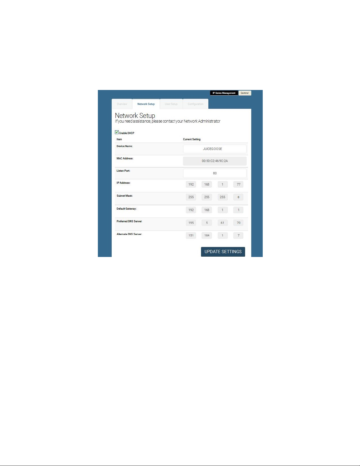
COMMUNICATIONS LINES
Ethernet (Network)………….......................................................……RJ-45 (8 Wire)
RS232 (not on IP50/IP50-RX).... ......................................................RJ-11 (3 Wire)
COMMUNICATIONS PROTOCOL.............HTML, TCP, UDP, RS232 (except IP50/IP50-RX)
OPERATING TEMPERATURE RANGE (degrees Fahrenheit)
Operating....................................................................................................32 to 158
Storage......................................................................................................-40 to 185
Page 3

FRONT PANEL FEATURES
ROCKER SWITCH - The primary intent is for the iP Series to be controlled via a
remote RS232 or Ethernet link. This switch serves as a fail safe control device
in the event a remote RS232 or Ethernet connection is not available or function-
ing. Moving this switch to the UP position will cause the iP Series to turn on the
power PODs in a prescribed timed sequence. The default timing is two seconds
between each POD activation. This timing can be changed by accessing the on
board web server. Moving this switch to the DOWN position will cause the unit
to turn off the POD outlets in the reverse order. (Switch is not present on IP50/
IP50-RX model).
RECESSED SLIDE SWITCH - As a second fail safe control point, this switch
can be used to manually turn on all POD outlets in the unlikely event of failure
of the control circuitry contained in the iP Series. This switch will turn on all
POD outlets simultaneously. When the switch is returned to it’s “off” position the
iP Series will revert to the prior state the unit was in. (Switch is not present on
IP50/IP50-RX model. The manual override feature on the IP-PD1-4 is activated
as a position on it’s rocker switch).
Network LED - The Network LED indicates connectivity to a network or com-
puter. If this LED is flashing it means no network connection is detected, when
solidly lit it means it has detected and connected to a network.
POD LEDs - As each of the POD duplex receptacles on the back of the iP se-
ries turns on a corresponding LED on the front of the unit will light. Each LED
will turn off when the POD turns off (except IP-PD1-4).
(IP50/IP50-RX models only) NETWORK (Ethernet) PORT - This RJ45 connec-
tor is for connecting to your PC, router or local area network using a TCP/IP
link.
BACK PANEL FEATURES
NETWORK (Ethernet) PORT - This RJ45 connector is for connecting to your
PC, router or local area network using a TCP/IP link.
RS232 PORT- This RJ11 connector can be used for remote control of the iP
series via RS232 protocol over distances not to exceed 50 feet. (not available
on IP50/IP50-RX)
CONTROLLABLE PODs (outlets) There are 3 duplex receptacles on the back
of the IP15 models, 4 on the IP-PD1-4 model and 2 outlets on the IP50 models.
Each is rated for a maximum of 15 or 20 amp load (dependant on model) and
each is controllable to turn on or off independently of the others. When the on
board sequencing process is used POD 1 will turn on first, followed in order by
the other PODs. They will turn of in reverse order using this same process.
UNSWITCHED OUTLET - This single outlet is rated for a maximum load of
fifteen amps on the IP1515/IP1515-RX/IP50/IP50-RX and twenty amps on the
IP1520/IP1520-RX. It will have power any time the iP device is plugged into a
live AC receptacle. Page 4

DETAILED INSTALLATION AND SETUP
Connecting to the iP device using a Router.
1. Connect the iP device to your network router using a Cat 5 cable plugged
into the RJ45 “Network” port on the rear of the unit and the other end to your
network router.
2. Plug the iP device power cord into a live AC receptacle, such as a wall outlet.
Note: The iP1520 requires a 20 amp, NEMA 5-20R receptacle and the IP-PD1-
4 is hardwired by an electrician.
3. The iP device will take a few seconds to boot up and configure itself at which
point the Network light on the front of the unit should illuminate and remain on
without blinking, indicating network connectivity. If the Network light blinks
check the cable connections.
4. Open a web browser on your device and type in the following address on the
navigation bar to access the iP device: http://juicegoose
Be sure to type exactly as shown. No domain such as .com should be added. If
you cannot connect to the device contact your System Administrator
5. You will be presented with the login box. Enter the following initial username
and password (these can be changed later):
User: admin
Password: juicegoose
Connecting to the iP device using a Crossover CAT5/6 cable.
To connect the iP device to a PC directly you may need to change the proper-
ties of your internet connection/IP address.
1. Plug the CROSSOVER cable into the PC network socket and the other end
into the iP device Network socket .
2. Plug the iP device power cord into a live AC receptacle, such as a wall outlet.
Note: the iP1520 power cord requires a twenty amp, NEMA 5-20R, receptacle
(for the IP-PD1-4 ensure it is hardwired and the circuit is operating).
3. The iP device will take a few seconds to boot up and configure itself at which
point the Network light on the front of the unit should illuminate and remain on
without blinking, indicating network connectivity. If the Network light blinks
check the cable connections.
4. In Windows go to your start menu and navigate to the control panel. Then
choose the Network Connections” icon. (For other operating systems consult
your system administrator or refer to the operating system’s user/help section).
Page 5

5. Open Network connections by double clicking on it, select the LAN or HIGH-
SPEED icon, right click on this and select properties.
6. Click once on the Internet Protocol item that you will see at the bottom of the
list and select the properties button which is at the mid right.
7. Check the “Use the following IP address” box and then change the IP ad-
dress to: 192.168.1.1, then change the Default Gateway address also to:
192.168.1.1.
8. Click OK and then close the network box.
9. Open a web browser on your PC and type in the following address on the
navigation bar to access the iP device: 192.168.1.77.
10. The iP device login box will appear, enter your login details and operate the
iP device.
You can also configure the required IP address and any network/RS232 set-
tings you require using the RS232 connection. See page 14 for detailed RS232
commands and setup requirements.
The iP Series Management section is accessible from the top right link named
“Management”. It consists of 4 tabs;
Overview—Which shows the current configuration of the iP device.
Network Setup– Where you can configure IP address and other required net-
work settings dependant on your personal network
User Setup– Where you can set the username and password for both the
admin account and user account
Configuration— Which allows you to configure RS232 baud-rate setting and the
Power Cycle feature of POD1.
Page 6

OVERVIEW
The Overview Tab displays the current settings of the unit and the MAC ad-
dress. This page is useful for retrieving all the information you may need to set
up the iP device on your network. If you have DHCP enabled, the IP address
your router/DHCP server assigned can be viewed here.
Page 7

NETWORK SETUP
In the above image you can see the network setup tab accessible when logged
in as Admin.
The Enable DHCP is checked by default. This will result in the router or DHCP
server assigning the IP address of the unit which will then be visible on the
OVERVIEW tab.
The Device Name field sets the DNS lookup name of the device. This can be
anything you choose. Just populate the field with the name and then save with
the update settings button. DNS named devices allow for easier identification
on a network.
If you wish to set the IP address manually to conform with your personal net-
work the fields are provided to do this. You must first disable the DHCP check
box and then enter the IP address, subnet mask, default gateway and preferred
DNS values in compliance with your local network.
The Listen Port is used for remote access from outside your network. The de-
fault is set to 80. But this can be changed to any port you select that otherwise
is not being used by any other attached system. See page 13 for further details
on the port address and how it relates to remote access.
Page 8

USER SETUP
The user setup tab is where you configure the Admin and User account pass-
words. You can change the username and password on both accounts by typ-
ing in the changes in the corresponding fields. There is a second password field
for both accounts that verifies you typed the password in correctly. If you did
not, an error message will be displayed when trying to save the changes.
Once you have set the desired username/passwords hit the ‘SAVE’ button and
the changes will be made and the unit will reboot. You may hit the Cancel but-
ton if you decide you don’t want the changes and the username/passwords will
remain unchanged.
Only the Admin login has access to the setup and configuration page. This login
should only be used by authorized people as changes can render the unit in an
unusable state if the wrong data is entered. A factory reset would then have to
be applied.
The User account has access to only the POD and Sequence control page.
Multiple Admins and Users can be logged into the device at the same time
which allows uninterrupted operation from multiple locations without the need
for other users to log out first. The commands are processed based on the last
command issued.
Page 9

CONFIGURATION
This is the configuration tab. Here you can assign a new IP or control the device
via RS232 commands (see page 13 and 14 for the list of commands). This will
require a special cable (detailed drawing on page 13). You can also enable/
disable UDP and TCP.
The only field that is variable for RS232 communication is the Baud rate which
is set at a default of 19200bps. RS232 communication uses COM1. Your com-
puter will need to be set to the same values as follows; Baud rate=19200, Par-
ity=None, Data Bits=8, Stop Bits=1.
Once you have configured the PC’s COM1 port to match the above values you
can then use a Terminal program to access and issue the RS232 commands.
There are several free terminal programs available such as Microsoft Hyper-
terminal. Or you can download one direct from the iP product page on the Juice
Goose website at http://juicegoose.com/product-ip-1520.html
Page 10

POWER CYCLE FEATURE
Also on the configuration tab is the Power Cycle control feature. The Power
Cycle feature is useful for rebooting routers should a connectivity issue arise.
Simply plug the router into POD1. Should a router lock up occur the units will be
rebooted via the power cycling of POD1 when your chosen domain cannot be
PINGed by the iP device. This feature ships disabled and can be enabled using
the checkbox.
Before you enable this feature, be sure to configure the settings you require.
After you enable the Power Cycle feature the settings cannot be changed
unless you disable the feature again.
Please note: if you have a Dynamic IP address it is not advisable to plug your
Cable/DSL modem into POD1 as a reboot of the modem could result in a new
IP address being assigned to the modem and so could result in remote access
issues if you do not know what the new IP address is. We suggest plugging the
modem into the Unswitched (always on) outlet of the iP device and the router in
POD1. If you have a static IP address this is not an issue and the modem can
also be plugged into POD1.
There are 3 user definable fields to this feature.
The ‘PING Address’ field is the internet address that the unit will use to check
network connectivity. The default is our web domain (www.juicegoose.com) and
can be left as is. If you wish to choose another domain simply type the address
in this field.
The ‘PING Every’ field is how often you want the iP device to check for connec-
tivity. The default is 30 seconds and can be changed to any value (in seconds)
you choose. It’s recommended that you don’t go below 30 seconds to allow any
attached devices ‘boot up’ time.
The ‘Power Cycle After’ field is how many failed PING attempts the unit will
carry out before rebooting POD1. The default is set to 2 tries but the user can
define any value.
Once you have completed all setup fields as desired hit the save button at the
bottom of the page to update the unit and reboot it.
Page 11

REMOTE CONTROL AND MONITORING
Using the On Board Web Server
TURNING POWER ON AND OFF - On the Control page, each of three PODs
has associated with it a virtual On/Off button (Activate) and an On/Off indicator
(Status). Clicking an On/Off button turns the corresponding POD on or off.
When a POD is on the Status indicator will be green as if on. When a POD is
off, it’s Status indicator will darken, as if off.
POWER MONITORING - The Current indicator will show the amount of electric
current flowing through a particular POD. This meter is accurate to the nearest
0.1 amperes for levels between 0.2 and 20.0 amperes. Current measurement is
RMS, averaged over a period of three seconds. Because the iP15 only meas-
ures current in one direction, from the outlet to the load, applications that feed
current back to the supply (for example inductive loads such as motors) will not
be measured accurately. (This feature not available with the IP50/IP50-RX)
SEQUENCING SETTINGS - Rather than turning each POD on and off individu-
ally, in applications where it is desired to turn the outlets on and off in a coordi-
nated sequence, a macro program can be set to turn the PODS on (1-2-3) and
off (3-2-1) in order with the click of a virtual button. Under the Sequence head-
ing on the Control page enter a desired number of seconds for the delay of turn-
ing the PODS on and off. The default value is two seconds. Clicking the Acti-
vate button will turn the outlets on or off in the prescribed order. The status of
the PODs is indicated below the Status heading on the Control page.
REMOTE OPERATION OF iP device - To access the iP device from a different
network other than the one the iP device is using, you need to first assign the
iPdevice with a PORT address on the Network setup page and then assign this
on your router. Log in to your router and enable the PORT FORWARDING
feature (Sometimes called Virtual Server) using the assigned iP device’s IP
number you chose and the port number you assigned. Each router’s port for-
warding is different. So see your routers manual for help with configuring this.
Once you have port forwarding setup you can access the iP device from a re-
mote network by typing the IP address and PORT address into your browser
bar. The PORT address is added to the end of the IP address separated by a
colon.
Example 200.100.075.050:80 - In this example “80” is the port address.
If you have enabled the port forwarding correctly on your router you will be able
to access the iP device from any location in the world.
Page 12

RS232 CONTROL AND MONITORING
(Not available on the IP50 or IP50-RX)
To operate the iP device using RS232 you will need a suitable cable from the
PC to the iP device RJ11 RS232 port on the rear of the unit. Below is the pin
out for a RJ11 to female DB9 cable. This cable will need to be constructed or
purchased. (NOTE: RS232 control not available on IP50/IP50-RX model).
RS232 CABLE PINOUT
RS232 COMMANDS
Using Terminal Software such as Windows Hyper Terminal or Micro Terminal
which you can download from our website at http://juicegoose.com/product-ip-
1520.html, the following commands can be issued to the iP device.
NOTE: A DEACTIVATE command must be issued first to ensure the physical
sequence up/down switch position does not override the RS232 commands.
ACTIVATE - Enables the sequence up/down switch on the front of the
iP15
DECACTIVATE - Disables the sequence up/down switch on the front of
the iP device
POD1ON – Turns POD 1 on
POD1OFF – Turns POD 1 off
POD2ON – Turns POD 2 on
POD2OFF – Turns POD 2 off
POD3ON - Turns POD 3 on
POD3OFF – Turns POD 3 off
Page 13

ALLON—Turns all PODs on without sequence
ALLOFF – Turns all PODs off without sequence
SEQUP(X) – Sequences up all PODs from 1 to 3, where (X) is the number of
seconds between sequence events (e.g. A 2 second sequence would be SE-
QUP2)
SEQDOWN(X) Sequences down all PODs from 3 to 1, where (X) is the number
of seconds between sequence events (e.g. A 2 second sequence would be
SEQDOWN2)
POD1CURRENT (Reports current draw on Pod 1)
POD2CURRENT (Reports current draw on Pod 2)
POD3CURRENT (Reports current draw on Pod 3)
DHCPON - Enables DHCP on the iP15
DHCPOFF - Disables the DHCP on the iP device. You will want to disable
DHCP before entering any new network settings via RS232 or the changes will
be lost when connecting the unit to a network.
SETIP XXX.XXX.XXX.XXX - Sets the IP address of the unit where ‘X’
represents your chosen numerals.
SETMASK XXX.XXX.XXX.XXX - Sets the subnet mask of the unit
where ‘X’ represents your chosen numerals.
SETGATEIP XXX.XXX.XXX.XXX - Sets the gateway of the unit where
‘X’ represents your chosen numerals.
SETPDNS - Sets the primary DNS IP address.
SETSDNS - Sets the secondary DNS IP address.
INFO - Shows all current settings
RESTART - Restarts/Reboots the iP device. Use this command after
making your changes.
End of line (EOL), or line break, is a special sequence of characters
signifying the end of a line of text.
EOL is defined as LF ( line feed, 0x0A ) and CR (carriage return,
0x0D ) combined into one (LF+CR, CR+LF).
The iP1520 firmware ignores LF. However, it waits for CR to find the
end of command.
In other words, EOL should be present as LF+CR, CR+LF, or CR at
the end of every command issued.
WRITING CUSTOM CONTROL INTERFACE
If you wish you design your own driver/interface for the iP device this can be
done by incorporating the predefined RS232 protocols as listed in the RS232
Control and Monitoring section of this Manual into your software.
Page 14

RAW TCP CONTROL
It is possible to control and monitor iP device over Ethernet using raw TCP pro-
tocol. In this mode, any PC ( Windows, Linux, Mac ) can connect to the iP de-
vice over a TCP/IP connection using a suitable TCP/IP client program. Once
the connection is made, the serial port console and its commands are available
to the user over TCP/IP as if the user was connected to IP device over the local
serial connection.
By default, TCP feature is disabled due to security reasons. This can be en-
abled through the web interface. The default TCP port is 33333; this can also
be changed through the web interface.
To enable TCP feature, click on iP Series Management link on the web inter-
face and then click on Configuration tab. Mark the button called Enable in the
TCP section. Change the default TCP port, if needed.
Page 15

To connect to IP device over TCP, simply start your TCP client program ( such
as Hercules or PuTTY) and specify the IP address of the iP device and the TCP
port. Start the connection ( many programs have a Connect button to start the
connection ) and type iP device console commands such as Help. You should
see the reply to the command on the TCP client terminal window. See page 13
and 14 of this manual for a full list of the console commands available.
Instead of a dedicated client program, it is also possible to use Telnet command
to establish the connection. For example, from Windows command prompt,
type:
telnet <IP Address> <Port>
where <IP Address> is the address of the iP device to connect and <Port> is
the TCP port to use.
Example: telnet 192.168.1.22 33333
Note: If there is no activity on the console for 10 minutes the TCP connection
will be closed automatically.
POWER LINE CONDITIONING
The iP1515-RX. iP1520-RX and iP50-RX feature a patented Hybrid Filter Tech-
nology to clean up and prevent both normal mode (line to neutral) and common
mode (ground line) surges and interference. Many popular power conditioners,
including “series mode” devices are less effective on normal mode and have
almost no protection against common mode events.
Energy surges as great as 6,000 volts are reduced to a maximum of 10.0 volts
between line and neutral and 0.50 volts on the ground line. The RX Series cir-
cuitry includes components that act as a low pass filter which reduces high fre-
quency electromagnetic and radio frequency interference.
This unit also protects against external wiring faults. Relays in the RX prevent
operation in conditions of incorrect hot, neutral or ground wiring or in the event
of dangerously high voltage. If this unit is plugged into an outlet that is not
properly wired—if hot, neutral and ground are not properly connecte—power
will not pass to the receptacles. Therefore, a proper ground connection is re-
quired for this unit to operate. The same safety measure functions when incom-
ing voltage exceeds 155 volts.
Page 16

UDP CONTROL
It is possible to control and monitor iP series products over Ethernet using UDP
protocol. In this mode, any PC ( Windows, Linux, Mac ) can connect to the iP15
using a suitable UDP capable client program. Once the UDP port is opened, the
serial port console and its commands are available to the user over UDP as if
the user was connected to iP device over the local serial connection.
By default, UDP feature is disabled due to security reasons. This can be en-
abled through the web interface. The default UDP port is 30333; this can also
be changed through the web interface.
To enable UDP feature, click on iP Series Management link on the web inter-
face and then click on Configuration tab. Mark the button called Enable in the
UDP section. Change the default UDP port, if needed.
Unlike TCP, UDP is a connectionless protocol. Also, unlike TCP, UDP does not
guarantee delivery of messages. For simple console applications, this is not
critical and the message can be retyped if there is a problem with transmission.
See page 13 and 14 of this manual for a full list of the console commands avail-
able.
Page 17

POWER LOSS FEATURE
The power loss feature on the iP series products ensures that in the event of a
power outage the previous state is remembered when power is returned.
Effectively this means that if you have PODs in an activated state and the
power fails, when power is restored the PODs that were previously activated
will sequence back up in accordance with the sequence delay currently active.
To enable the power loss feature, click on iP Series Management link on the
web interface and then click on Configuration tab. You will see a check box
under the Power Loss Feature section. Checking the box enables the feature.
NOTE:
Please note, a delay of up to 5 seconds can occur between issuing a command
in the web server and the iP series product storing the state. So if power is lost
just after a command has been issued the state may not be remembered.
Page 18

TROUBLESHOOTING
The Juice Goose iP series are ruggedly constructed and contains quality com-
ponents. There are no user serviceable parts inside this device. Unauthorized
service will void all existing warranties and may result in equipment damage
and personal injury.
Should improper performance be observed consult the following guidelines for
diagnosis.
THE iP DEVICE WILL NOT POWER UP.
a. Check to see that main utility power is available.
b. Check that the circuit breaker on the iP device is not tripped.
c. Check the Network LED on the chassis. If it is not lit the iP device is proba-
bly not receiving power. Remove power from the iP device by unplugging it
or turning off the circuit breaker that feeds the unit. Then restore power.
d. Check that utility power is not at fault; that hot, neutral and ground are prop
erly connected and voltage is at a proper level near 120.
THE iP DEVICE WILL NOT POWER DOWN.
a. It is likely that when a unit fails to turn off the cause is similar to that which
would cause a unit to fail to turn on.
b. Follow steps outlined in the power up solution above.
I CANNOT CONNECT TO THE iP DEVICE VIA MY NETWORK.
Ensure your router has DHCP enabled (see your router’s user manual to enable
this feature). Then type http://juicegoose to access the login screen.
Check you are using the correct cable, standard CAT5 cable for router connec-
tion, crossover cable for direct to PC connection.
If you are connecting directly to a PC you will have to configure your computer
to have an IP address of 192.168.1.1. See your operating systems help file on
how to do this. We recommend you setup the devices initially on a router.
Are you using the correct username and password? If you are accessing the
login page and your login is failing you might need to reset to factory default
and try again if you have forgotten the correct username/password combination.
If you are trying to connect from a remote network ensure you are trying to ac-
cess using the correct IP address and PORT number which were assigned to
the unit. Port forwarding may need to be enabled on the remote unit’s network
router (see your administrator).
Page 19
This manual suits for next models
9
Table of contents
Other JuiceGoose Power Distribution Unit manuals
Popular Power Distribution Unit manuals by other brands

Marway
Marway Optima 532 Series Operating Guide and Reference

Compaq
Compaq 207590-B21 - Power Distribution Unit Strip Quick install guide

LEGRAND
LEGRAND Server Technology PRO4X user guide

Ormazabal
Ormazabal cgm.3 system Series General instructions

Seg
Seg WI Series Reference manual

brennenstuhl
brennenstuhl Professional BSV 5 5/4 N5160 AT operating instructions