_____________________________________________________________________________________
2
1. GENERAL DESCRIPTION
1.1. The NPTFD1009 Fuse Panel provides
fused distribution of DC power to equipment.
The panel has 4 isolated fuse positions, each
consisting of a TFD fuse holder which can
accept both TLS and TPS style fuses. Alarm
circuits are provided to indicate and extend
alarm conditions for each fuse position.
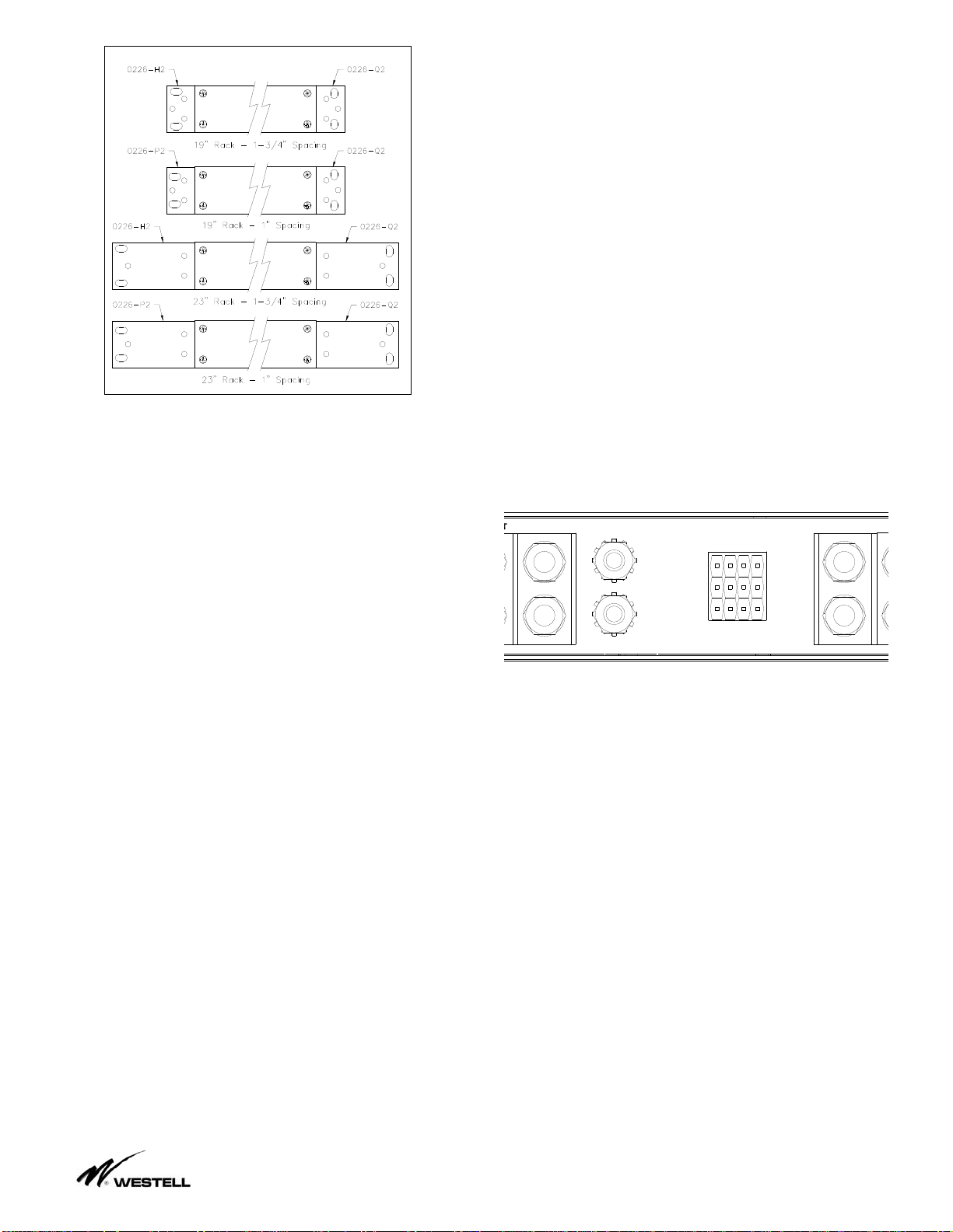
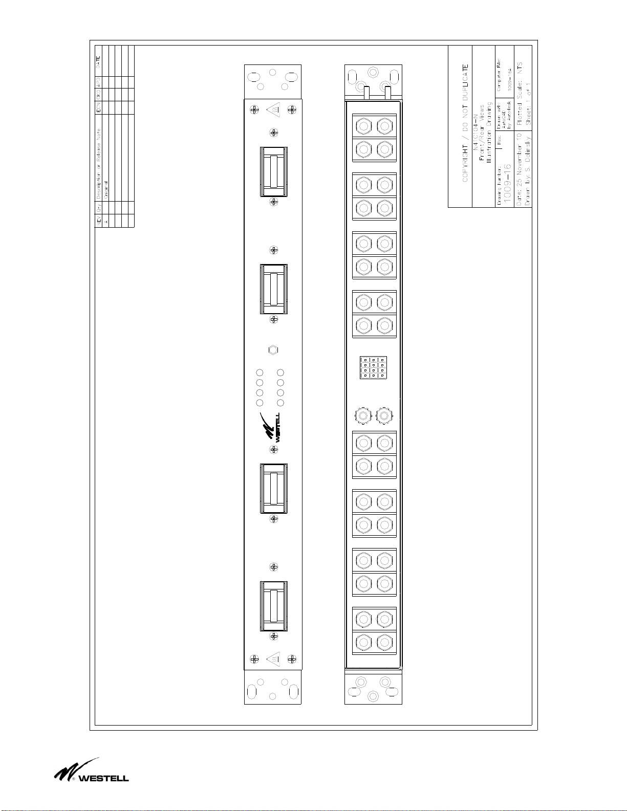
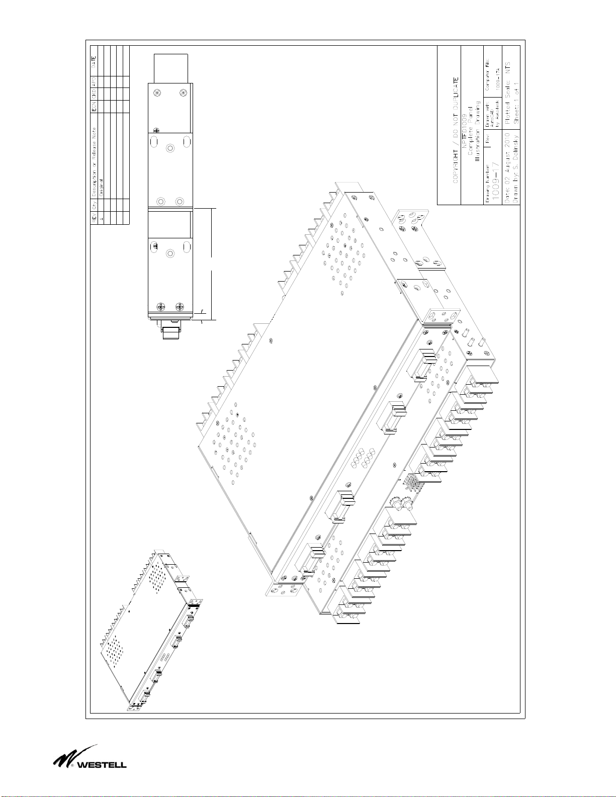
1.2. Wiring for the panel is accessible on the
rear of the panel. Power is connected via the
stud input and output blocks. Alarms are
connected via wire-wrap to the connectors on
the rear of the panel. Figure 1.2.1 shows the
connectors available on the rear of the panel.
Figure 1.2.1
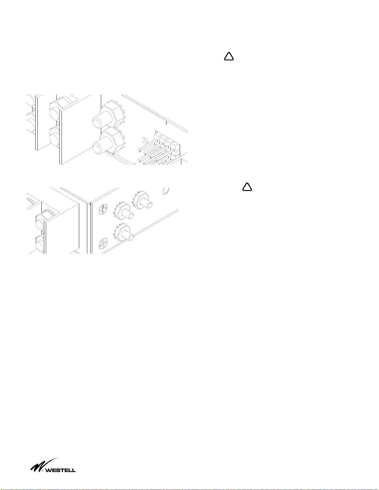
1.3. Power is provided to and distributed
from the panel by using properly rated cables
equipped with standard two hole lugs (1/4”
studs on 5/8” centers). Two hole lugs must
be used for this high current fuse panel to
function properly. Power is provided to the
load side equipment through TLS or TPS
style fuses. There is one fuse position for
each input position. Each fuse position can
distribute a maximum of 125 Amps.
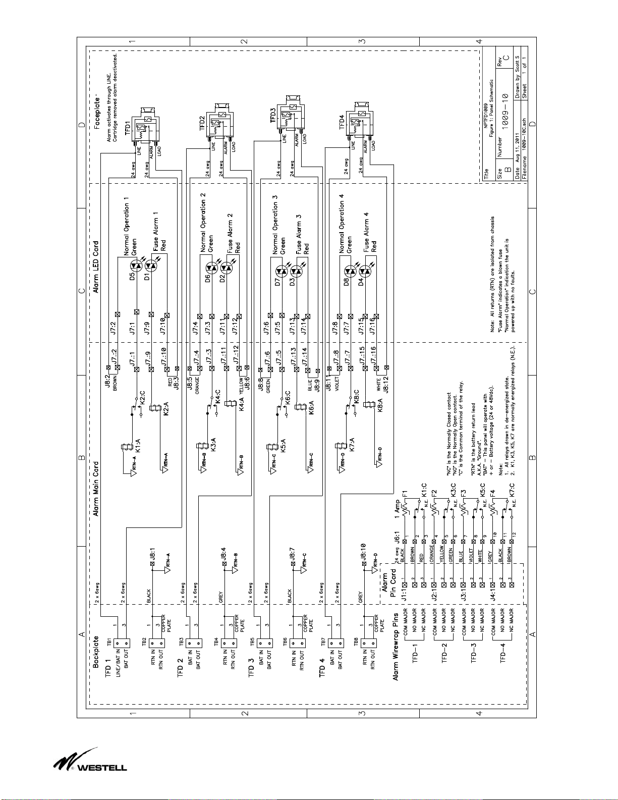
1.4. Alarm circuits are provided to indicate
and extend alarm conditions. Each TFD fuse
holder houses the main TLS fuse as well as a
GMT alarm indicating fuse. When the
cartridge is removed, the alarm is de-
activated. When an alarm condition is
present a red Fuse Alarm LED !will
illuminate. As well, the green Normal
Operation LED 9will extinguish to signal a
fuse alarm or input power failure and the
appropriate relay contacts will change states.
A set of dry “Form C” contacts is provided for
each fuse position to extend alarm conditions.
Each relay has a common (COM), normally
open (NO), and normally closed (NC) contact.
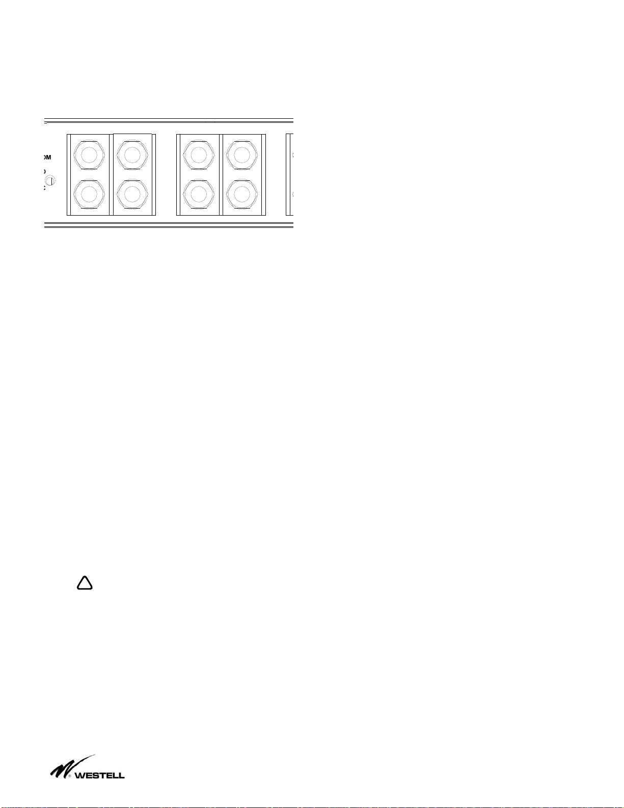
The local alarm LEDs are located on the front
of the panel as shown in Figure 1.4.1.
LED SYMBOL SIGNIFICANCE
GREEN 9NORMAL OPERATION
RED !BLOWN FUSE
1234
Noran TelBy !
Ì
9
125A MAX FUSE
Figure 1.4.1
1.5. The Fuse Panel is constructed from
0.050” steel and painted off-white. The panel
is shipped with mounting brackets that allow it
to be installed in both 19” and 23” wide racks,
with either 1.75” or 1” panel hole spacing
(occupies 1 RU in a 1.75” pattern rack).
2. APPLICATION
2.1. NPTFD1009 Fuse Panel is designed to
be used in the rack level distribution of DC
power. It is a rack mount panel that provides
fused DC power for 4 isolated circuits using
TLS style fuses in a TFD style fuse holder.
2.2 The NPTFD family fuse panels are
suitable for installation as part of a Common
Bonding Network (CBN) for electrically
bonding the shelf type chassis of this fuse
panel to its equipment rack (via mounting
brackets or chassis bonding studs). Note that
all power return inputs (RTNs) are electrically
isolated from each other and from the fuse
panel chassis. As well, this family of fuse
panels is suitable for restricted access
locations in Network Telecommunications
Facilities, and OSP.