InfraScan 753 User manual

360°Infrascan®
Passive Infrared Motion Sensor
Installation Instructions
®
Please leave these instructions at
the installation site.
753
Series

753 Series 360° Infrascan Installation Instructions
2 of 16 © 2012 Schneider Electric. All Rights Reserved.
Contents
1.0 Product Range..................................................................................................................3
2.0 Description........................................................................................................................3
3.0 Product Selection.............................................................................................................3
4.0 How it works .....................................................................................................................4
5.0 Identification of Parts ......................................................................................................5
6.0 Installation of Location....................................................................................................6
7.0 Field of View......................................................................................................................6
8.0 Mounting Procedure.........................................................................................................7
9.0 Wiring Diagrams - 753 2-Wire Infrascan ........................................................................9
10.0 Wiring Diagrams - 753R 3-Wire Infrascan....................................................................10
11.0 Commissioning...............................................................................................................11
11.1 Set Up for Walk Test ................................................................................................11
11.2 Soft Start Feature ....................................................................................................11
12.0 Troubleshooting........................................................................................................... 12
13.0 Technical Specifications................................................................................................13
14.0 Warning- Using the 753 with Special Loads ................................................................15
15.0 Warranty ..........................................................................................................................16
753 Series 360° Infrascan Installation Instructions
3 of 16
© 2012 Schneider Electric. All Rights Reserved.
1.0 Product Range
753 Infrascan 360 Degree, 240V a.c., 50Hz, 2-Wire, 2A,
20 Minute
753R Infrascan 360 Degree, 240V a.c., 50Hz, 3-Wire, 10A,
20 Minute
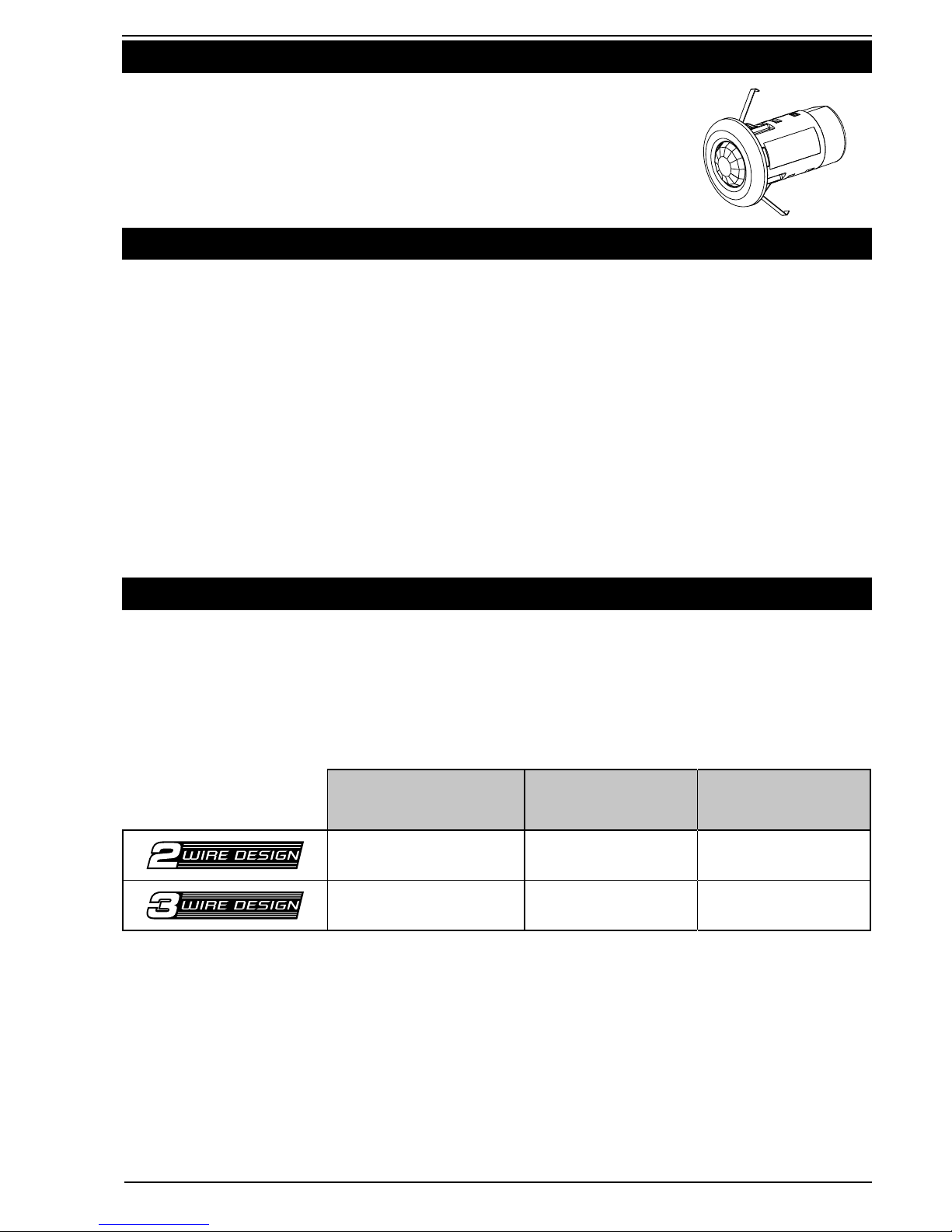
2.0 Description
The Clipsal 753 Series 360 Degree Infrascan is a highly reliable, state-of-the-art
passive infrared (PIR) occupancy sensor. The unit utilises an advanced quad-
element sensor array allowing instantaneous detection of movement and features
a massive 14 metre detection range.
The unit also features a slimline, fully recessed mounting facility, making it one of
the world’s most sleek and unobtrusive 360°sensors available.
The unit is designed to monitor the immediate environment, and detect people
moving within its field of view. When movement is detected, the unit will activate an
electrical load, such as a light, in response to that movement.
Designed and developed in Australia, the unit offers benefits in security, energy
management, hospitality and true ‘hands-free’ switching convenience in a wide
range of applications.
3.0 Product Selection
Be sure to select the appropriate Infrascan product to suit your application:
• the753isa2-wire(doesnotrequireNeutralconnection),andcanonlyswitcha
limited range of load types.
• the753Risa3-wiredevice(requiresNeutralconnectiontooperate)capableof
switching a wide range of load types.
* Please refer to Technical Specifications for further information about compatible load types.
Catalogue Number Neutral
Required Maximum Load*
753 NO 2A
753R YES 10A
753 Series 360° Infrascan Installation Instructions
4 of 16 © 2012 Schneider Electric. All Rights Reserved.
4.0 How it Works
With power applied and a suitable load connected, the Infrascan can detect any
moving infrared source (for example a person) that may intrude upon its field of view.
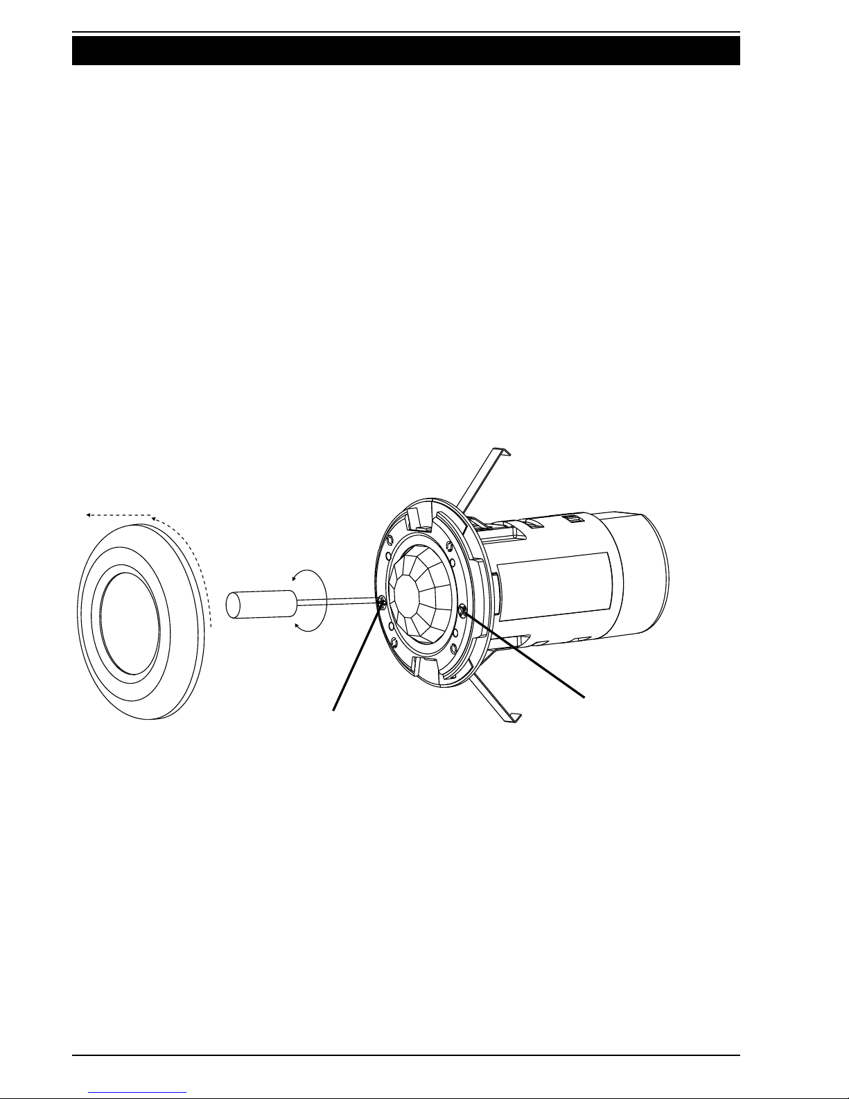
BoththeLight-LevelandTime-Onsettingsareuseradjustablebyremovalofthe
frontsurround.Simplytwisttoremovethecoverandadjusttrimpotasrequired.
TheLight-Leveladjustmentactivatestheloaddependentontheambientlight
levelintheeldofviewofthesensor.Thisadjustmentcanbesettoallowthe
Infrascan to operate the load at any light level between full daylight and almost
complete darkness. For example, the user can ensure the load is only activated
when movement is detected at night time. During the day time, when there is
adequate natural light, the unit can be set so it does not activate the load, as it is not
necessary to do so.
TheTime-Onadjustmentvariesthetimespanthattheloadwillremainonafter
the infrared source moves out of, or stops moving within the field of view. The
loadwillautomaticallybeswitchedoffaftertheTime-Onperiodhaselapsed.Any
period between 5 seconds and approximately 20 minutes may be set by the time
adjustmentscrew.
Light-LevelAdjustment Time-OnAdjustment
Twist to Remove Surround
Note
• Thesensorheadisspeciallydesignedtogiveoptimumperformanceandis
sealed to prevent water or dust from entering the unit. Under no circumstances
should it be tampered with. There are no user serviceable parts inside.
• Donotapplyanypressureontheactualsensorlensitself,asthismaydamage
the lens, and adversely affect the performance of the unit.

753 Series 360° Infrascan Installation Instructions
5 of 16
© 2012 Schneider Electric. All Rights Reserved.
5.0 Identification of Parts
Note
• Theunitissuppliedwithanoptionalzonemask,designedtoblocktheunitfrom
detecting motion in unwanted trip areas. This might include a smaller office
space with an open doorway, where it is not desirable to activate lighting when
people pass by the open door.
• Thezonemaskincorporatesaseriesofstagedtear-awaysections,allowingfull
customisation of the field of view. Tear away sections where you want detection
to take place.
• Totthezonemask,removethesurroundanduncliptheremovablespacer.
Clip the zone mask in place and replace the surround.
• Additionalzonemasksareavailable(ClipsalCatalogueNumber753MASK).
Surround
Spring Clips
Side Cable Entry
Apertures
Cable Clamp
Top Cable Entry
Terminal Cover Screw
Terminal Cover
Sensor Lens
UserAdjustments
Removable Spacer
753MASK-ZoneMask
Figure 2

753 Series 360° Infrascan Installation Instructions
6 of 16 © 2012 Schneider Electric. All Rights Reserved.
6.0 Installation Location
An Infrascan must be positioned correctly to ensure effective operation. The field
of view is optimum when the sensor head is mounted in a vertical position at a
height of 2.4 metres and the approach path is across the face of the sensor.
Note
• DonotmounttheInfrascanclosetoobjectswhichcancreaterapidtemperature
changes, e.g. air conditioning vents, heater flues, moving water (i.e. fountains
and sprinklers). Avoid locations where condensation is likely to form on the lens.
• DonotmounttheInfrascanonanysurfacethatissubjecttomovementdueto
wind or other causes.
• Inallcases,locatetheInfrascansothattheapproachpathisacrosstheeldof
view and not directly towards the Infrascan, as a reduced detection range will
be observed.
7.0 Field of View
Arrows show direction of
approach for maximum
rated range.
Note:thattheeffective
field of view is circular,
approximately 14m
diameter, when mounted
on a ceiling 2.4m above
the floor.
8m (26 ft)
8m (26 ft)
6m (20 ft)
6m (20 ft)
4m (13 ft)
2m (7 ft)
0m (0 ft)
2m (7 ft)
4m (13 ft)
Top view at 2.4m mounting height
0m (0 ft)
Side view
2.4m (8 ft)
2.7m (9 ft)
3.0m (10 ft)
3.7m (12 ft)12m
(39 ft) 12m
(39 ft)
10m
(33 ft) 10m
(33 ft)
8m
(26 ft) 8m
(26 ft)
6m
(20 ft) 6m
(20 ft)
4m
(13 ft) 4m
(13 ft)
2m
(7 ft) 2m
(7 ft)
0m
(0 ft)
Floor
Ceiling
Note
• Thestatedeldofviewistypicalforfullbodymovementandissubjectto
variations caused by the type and quantity of clothing worn, as well as variable
background temperature characteristics and speed of movement.
• Rapidandlargetemperaturechangesmaybedetectedeveniftheyappeartobe
well beyond the field of view due to reflection off surfaces that are within the field
of view.
753 Series 360° Infrascan Installation Instructions
7 of 16
© 2012 Schneider Electric. All Rights Reserved.
8.0 Mounting Procedures
Step 1
Using a hole saw or otherwise, cut a 50mm (2”) circular hole in the ceiling
(or ceiling tile). Draw cable through hole.
Step 2:
Remove terminal cover screw and terminal cover to expose terminals. Remove
cable entry tear-away(s) from the terminal cover as required, to suit incoming
cable.
Top Cable Entry
Punch out the top cable entry hole, then fit the cable clamp to the terminal cover.
Push the two halves so that it snaps together, and clip onto the terminal cover
entry hole. The cable clamp wraps around the incoming cable. Feed cable through.
Side Entry
DONOTUSESIDEENTRY.
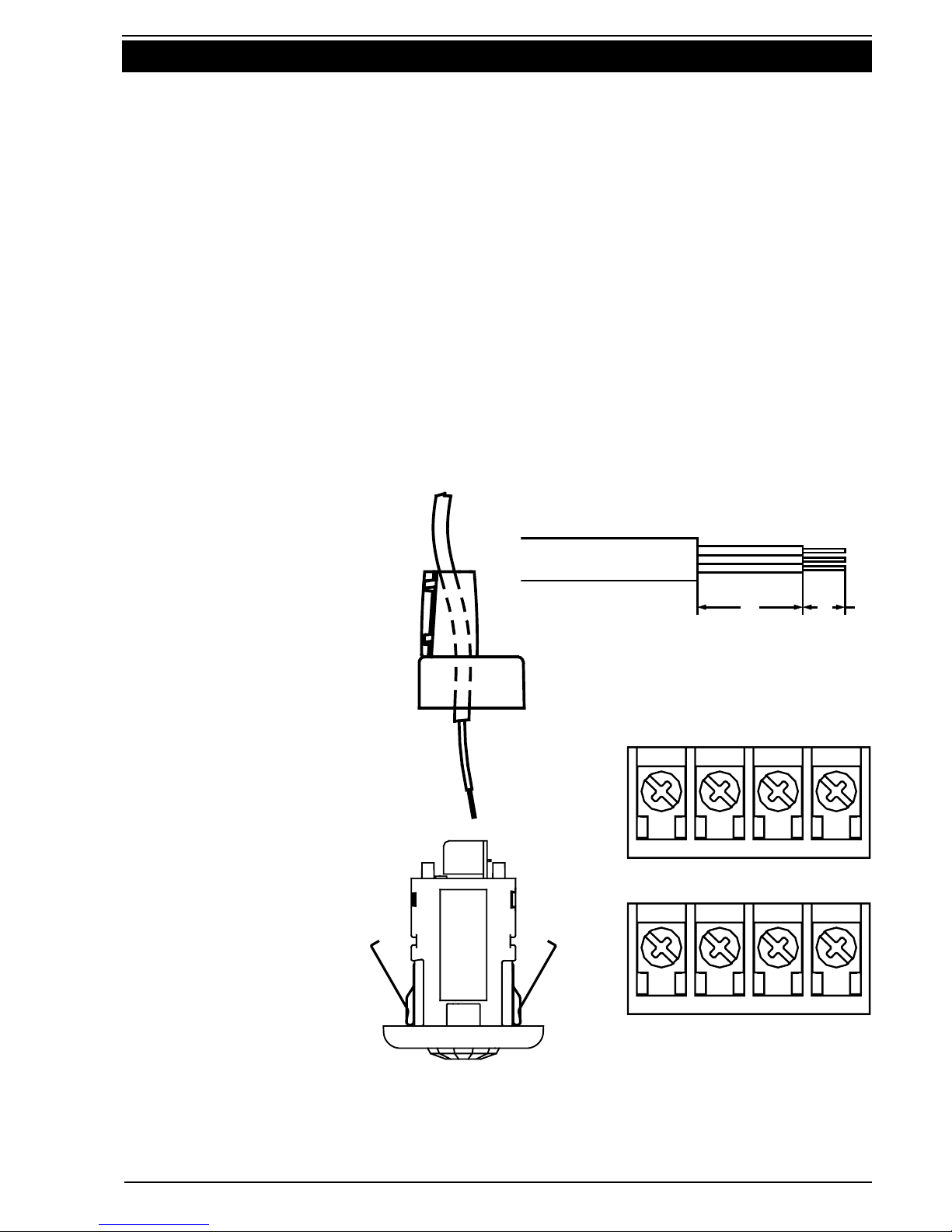
Step 3
Strip cable. Terminate
incoming wiring on the
appropriate terminals as
marked. Refer to Section
9 Wiring Diagrams
for further information
about wiring for different
applications.
Step 4
Fit the terminal cover,
and secure using the
terminal cover screw.
Step 5
Depress the outer
ends of the spring clips
towards the centre of the
unit and push the unit
through the hole until it
rests flat on the ceiling.
30 12
753 LOOP LOOP LOAD A/L
753R LOOP N LOAD A/L
Terminal Detail
Cut and Strip Detail
Figure 4
753 Series 360° Infrascan Installation Instructions
8 of 16 © 2012 Schneider Electric. All Rights Reserved.
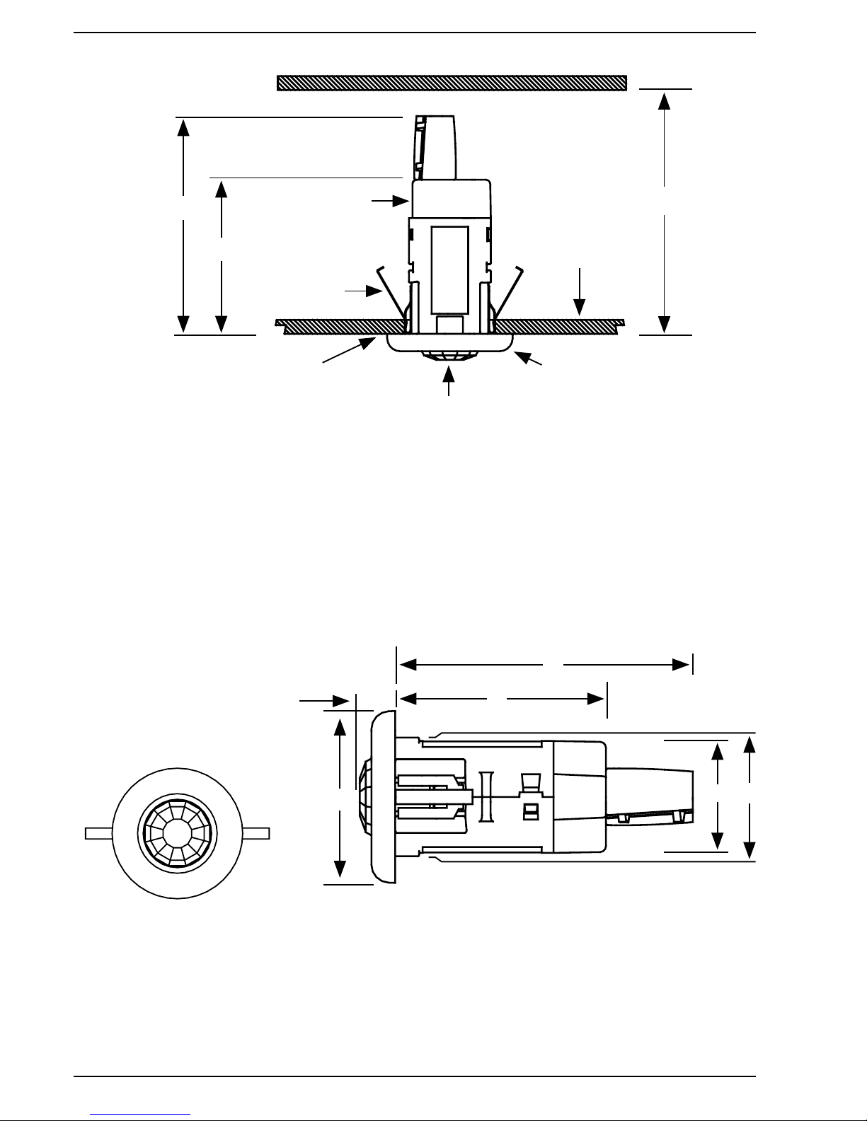
Note
• Whenmountinginsuspendedceilingsthereshouldbeatleast140mmbetween
the lower surface of the tile and the hard surface above.
• Donotapplyanypressureontheactualsensorlensitselfasthismaydamage
the lens.
NextLevel/Roof
Terminal Cover
Spring Clips
Minimum Ceiling
Thickness 8mm
Surround
Lens
Cut a 50mm Circular Hole
in Ceiling (or Ceiling Tile)
140mm Minimum
126.5mm
90mm
Figure 5
A
C
B
DE
F
A 72mm (2.83")
B 15mm (0.59")
C 89mm (3.50")
D 47mm (1.85")
E 50mm (1.97")
F 126.5mm (4.98")
Figure 6
753 Series 360° Infrascan Installation Instructions
9 of 16
© 2012 Schneider Electric. All Rights Reserved.
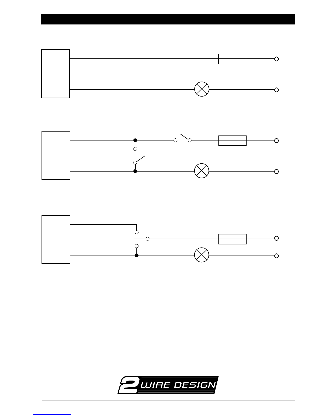
9.0 Wiring Diagrams - 753 2-Wire Infrascan
1(a) Automatic operation
1(b) Automatic with manual override ON or OFF
1(c) ON, OFF or AUTOMATIC operation using a three position switch
Note
• WhenswitchingtoAUTOforanyoftheabovecongurationstheInfrascanwill
turnon.Allow30secondsplusTime-Onperiodforthesensortostabilisefor
normal operation. Wiring diagram 1(a), without override switches is preferred as
there is no settling period.
• Morethanone753CANNOTbeconnectedinparalleltoacommonload.
If parallel connection of multiple devices to control a common load is required,
useCat.No.753R.
Load
Active/Line
10A Fuse or MCB
753
Black/White
A
N
Red/Brown
Load
Active/Line
10A Fuse or MCB
753
Black/White2x30Mor30MAM
Off
Auto
On Auto
A
N
Load
Red/Brown
Load
Active/Line
753
Black/White39MAOM
On
Auto 10A Fuse or MCB
Off
A
N
Load
Red/Brown
Load

753 Series 360° Infrascan Installation Instructions
10 of 16 © 2012 Schneider Electric. All Rights Reserved.
10A Fuse or MCB
753R
Load
Active
Black/Blue
Load
Red/Brown
White
Neutral
A
N
Auto
753R
39MAOM
10A Fuse or MCB
Off
Load
On
Active
Black/Blue
Load
Red/Brown
White
Neutral
A
N
On
10A Fuse or MCB
753R
2x30M or 30MAM
Auto
Load
Off
Active
Black/Blue
Load
Red/Brown
White
Neutral
A
N
Auto
10.0 Wiring Diagrams - 753R 3-Wire Infrascan
2(a) Automatic operation
2(b) Automatic with manual override ON or OFF
2(c) ON, OFF or AUTOMATIC operation using a three position switch
Warning
• Itisillegalforpersonsotherthanlicensedelectriciansorpersonsauthorised
by legislation to work on fixed wiring of any electrical installation. Penalties for
conviction are severe.
• Installationmustbecarriedoutinaccordancewithlocalwiringrules(AS/
NZS3000AustraliaandNewZealand).
753 Series 360° Infrascan Installation Instructions
11 of 16
© 2012 Schneider Electric. All Rights Reserved.
1Connect unit to mains power and allow at least 30 seconds for the unit to
stabilise before conducting any tests.
2Twist and remove the front surround and use a screwdriver to set the
‘Time-On’adjustmentfullyanti-clockwise(5secondtimerset).
3Setthe‘Light-Level‘sensoradjustmentfullyanti-clockwise(unitsetto
respond in light or dark conditions).
4
Walk slowly around the area in the desired field of view to confirm the load
is activated from within the desired area.
Check that the unit responds appropriately when entering the room.Check
that the unit does not trigger unnecessarily when walking past open entry
ways(e.g.adjoininghallwayorcorridor).Fitthezonemaskifnecessaryto
restrict the field of view to avoid nuisance tripping.
5Set the ‘Light-Level’ as desired for activation at dusk for normal operation.
6Setthe‘Time-On’intervaltothedesiredtimefornormaloperation.
7Replace the front surround.
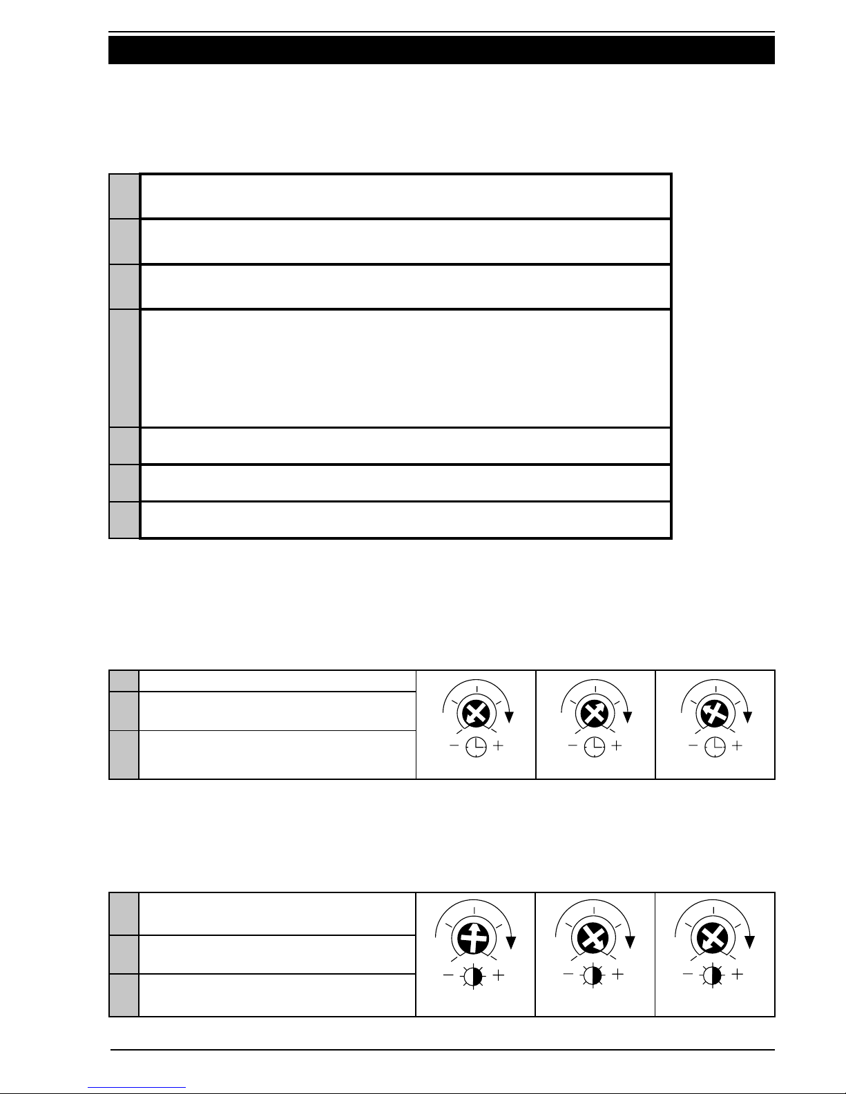
11.0 Commissioning
WhensettingtheTime-OnorLight-Leveladjustmentskeepclearofthefieldofview
whenassessingtheeffectoftheadjustment.
11.1 Set Up for Walk Test
11.2 AdjustmentOfTime-OnandLight-LevelSettings
Time-OnAdjustment
AdjustmentRange:Fivesecondsto20minutes.
Rotate clockwise to set required time-out period.
Light-LevelAdjustment
AdjustmentRange:Oneluxtofullsunlight.
Rotate clockwise to avoid having load activated when natural light is adequate.
aMinimum setting (five seconds).
a b c
bSet for areas with constant occupation
but infrequent movement.
cSet for areas with less occupation but
constant movement.
aTo activate the load at dusk, set
adjustmenttothisarea.
abc
bLoad activated at night only.
cLoad activated both day and night.

753 Series 360° Infrascan Installation Instructions
12 of 16 © 2012 Schneider Electric. All Rights Reserved.
12.0 Troubleshooting
Problem Possible Cause Possible Action
Light turns on
for no apparent
reason.
Momentary power failure. None,unitwillresetafter
Time-Out.
Unseen target. Checkforanimals,e.g.dogs/
cats, etc.
Extreme draughts of hot and
cold air.
Check doors, windows or air
conditioning outlets.
Trees/bushesmovinginthe
wind.
Re-aim sensor head.
Vehicular or pedestrian traffic
on edge of field of view.
Re-aim sensor head.
Light turns on
during daylight.
Wrong setting on Light
Adjustment.
Reset according to
Commissioning Instructions.
Lights do not
turn on in
dim and dark
conditions.
Wrong setting on Light
Adjustment.
Reset according to
Commissioning Instructions.
Light globe blown. Replace light globe.
Light remains
permanently on.
Manual override switch fitted
and set to Manual.
Reset according to
Commissioning Instructions.
Moving infrared source being
detected.
Note: do not mount too close
toobjectswhichcanchange
temperature rapidly, e.g. air
conditioner vents, heater
flues, moving water (i.e.
fountains, sprinklers).
Remove unwanted infrared
source. If unable to resolve,
blank off viewing window.
Light should turn off after
Time-Out.Iflightstillremains
on, call installer.
Note
• Takecarenottoscratchordamagethetranslucentwindowonthefrontof
the Infrascan, as it forms part of the optical detection system. For continued
optimum performance ensure that the window is cleaned periodically with mild
soap, water and a soft cloth.

753 Series 360° Infrascan Installation Instructions
13 of 16
© 2012 Schneider Electric. All Rights Reserved.
13.0 Technical Specifications
Catalogue Number 753 753R
OperatingVoltage 200 – 265V 50Hz a.c.
Maximum Load Current 2A 10A
Minimum Load (Watts)* 40W 0W
MaximumOff-StateLeakageCurrent 10mA 0mA
Stand-By Power Consumption < 1W < 1W
Conductors Required 2-WIRE 3-WIRE
NeutralRequired NO YES
OperatingTemperatureRange 0° - 50°C
Warm-Up Time 30 seconds
Rated Detection Field at Maximum
Sensitivity**
360°, circular detection field
14 meters diameter
OptimalMountingHeightforRated
Detection Field 2.4 metres
Timer Delay Range 5 seconds to 20 minutes,
useradjustable***
Light Level Inhibit Threshold Continuous from 1 lux to full sunlight,
useradjustable
Mounting Surface Ceiling mount
OverallDimensions 72mm diameter x 141.5mm high
Cut-OutDimension 50mm holesaw
Cables Accommodated 4 terminals, up to 2 x 2.5mm2
cable per terminal
753 Series 360° Infrascan Installation Instructions
14 of 16 © 2012 Schneider Electric. All Rights Reserved.
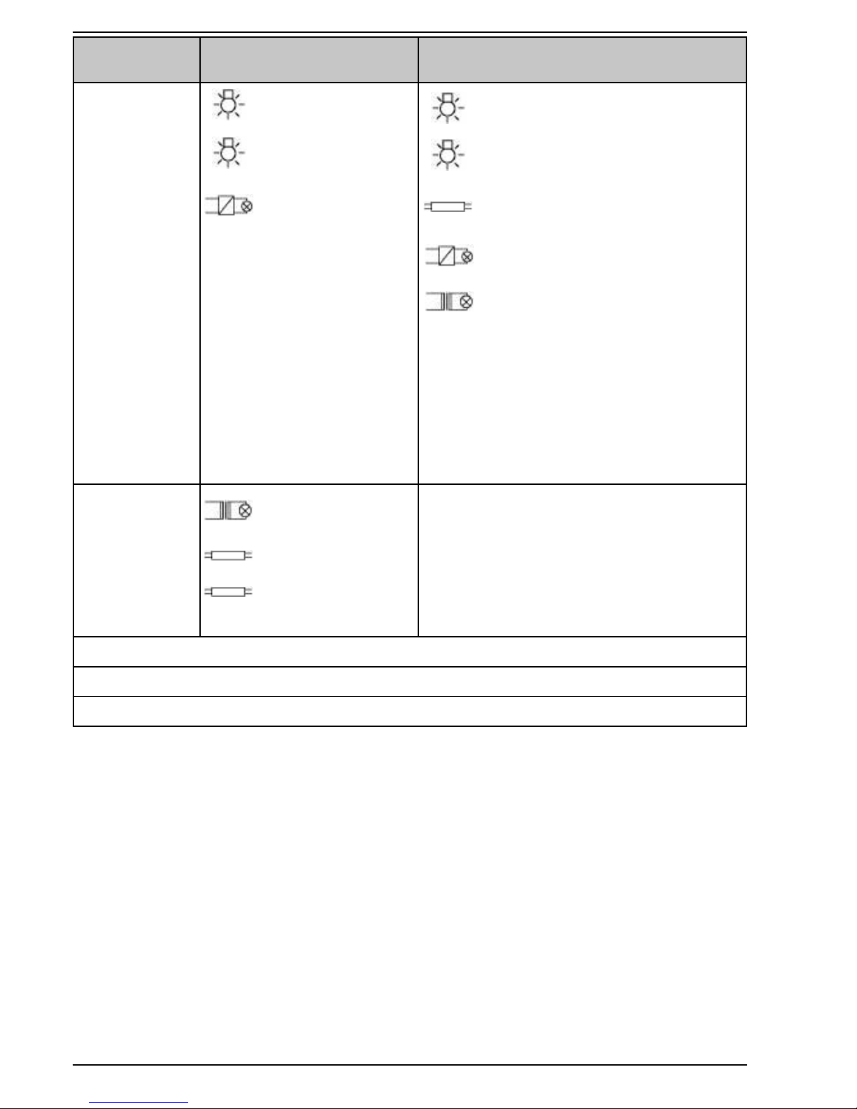
M
Catalogue
Number 753 753R
Compatible
Load Types
Incandescent
240V Halogen
Iron Core
Transformers****
Incandescent
240V Halogen
Fluorescent
Iron Core Transformers
Electronic Transformers
Small Motor Loads 5A
- Shaded Pole Induction
Motors 5A Max
(exhaust fans)
- Split Phase Induction Motors
5A Max (ceiling fans)
Incompatible
Load Types
Electronic
Transformers
Fluorescent
Loads
Discharge Lamps
Motor Loads
N/A
Specifications Typical @ 240V a.c., 25°C
Nouserserviceablepartsinside.
ThisproductisrecommendedforINDOORUSEONLY.
* The 753 2-Wire Infrascan must be connected to a minimum 40W load, unless the 31CAP (sold
separately) is fitted. Failure to do so may cause unexpected or erratic switching of the load.
** The range specifications given are based on a 90kg person travelling at greater than 1 metre
per second across the field of view, where there is a temperature differential greater than 5°
Celsiusbetweenthepersonandthebackground.Objectsthatarehotterormovingfaster(e.g.
motor vehicle on nearby roadway) may be detected at greater distances. A person covered in
heavy clothing or walking directly towards the sensor may not be detected until they get much
closer to the unit.
***OthermodelsareavailablewithlongerTime-Outranges,designated753Rxx
(wherexxistheTime-Outperiodinminutes).
****Onlyiron-coretransformerscompatiblewithelectronicswitchesmaybeusedtoensure
compliance with IEC 60669-2-1.
M
753 Series 360° Infrascan Installation Instructions
15 of 16
© 2012 Schneider Electric. All Rights Reserved.
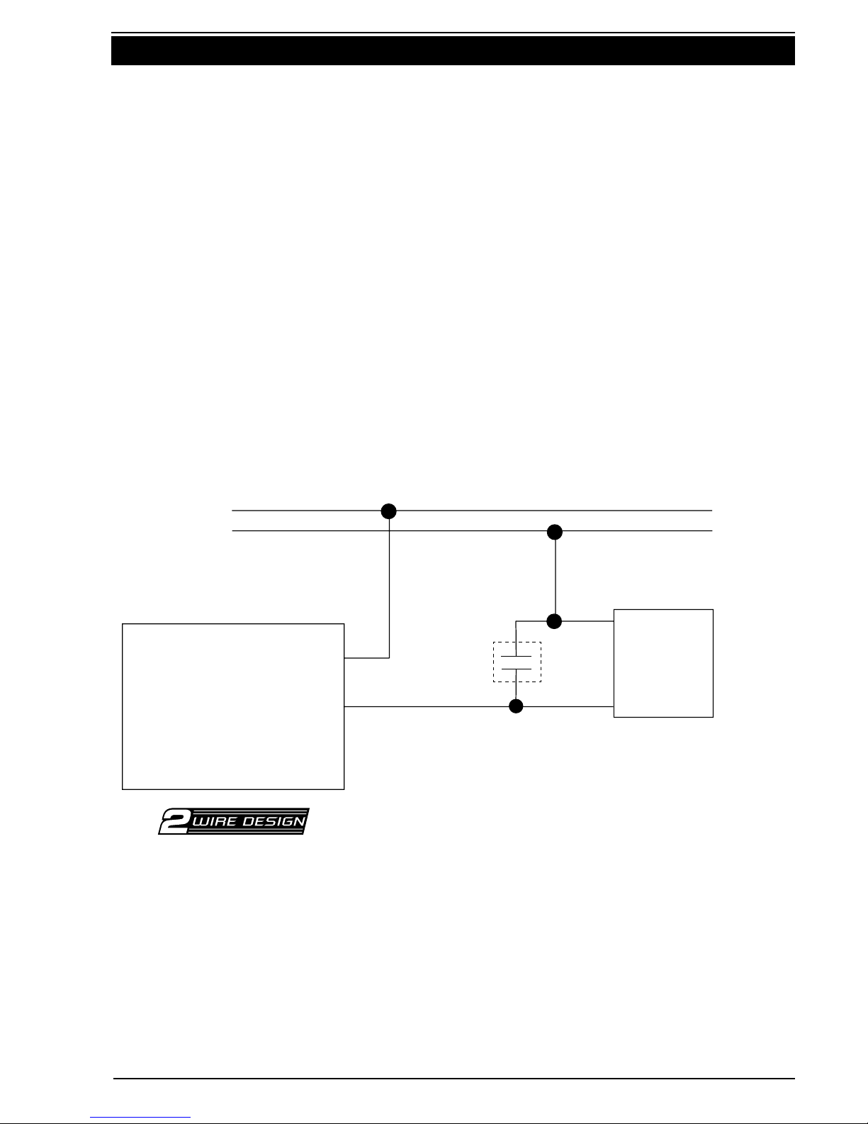
14.0 Warning- Using the 753 with Special Loads
Small Loads (<40W)
The 753 product can only drive loads greater than 40W. If you wish to drive a
smaller load, the 31CAP Load Correction Device is required to be fitted in parallel
with the load. For example: when driving a single contactor, be sure to use the
31CAP.
Loads which are Sensitive to Leakage Currents
The 753 is a two-wire device. Two-wire devices draw their power through the load.
Ifthisdeviceisusedinconjunctionwithaload,whichcannotprovideenough
continuous load current in the off-state, or the load is sensitive to a high off-
state leakage current (for example: relays, contactors, various loads with built-in
electronic control, etc.) a 31CAP Load Correction Device must be connected in
parallel with the load.
Small(Non-PowerFactorCorrected)FluorescentLoads
When a 31CAP is fitted, some small non-power factor corrected fluorescent
loads may be controlled using the 753. Success varies from manufacturer to
manufacturer. Recommend testing before installation. Installation must be
compliant with local wiring rules.
Line
Neutral
Line
Load
31CAP Load
31CAP Load Correction Device
753
Note
• Pleasenotethe753Risathree-wiredevice,andswitchestheloadusingan
internal relay. Power is not drawn through the load and so the 31CAP is not
required.

F1985/05
CLIPCOM24868June 2012
Schneider Electric (Australia) Pty Ltd
Contact us: clipsal.com/feedback
National Customer Care Enquiries:
Tel 1300 2025 25
Fax 1300 2025 56
Schneider Electric (Australia) Pty Ltd reserves the right to change specifications, modify
designs and discontinue items without incurring obligation and whilst every effort is made to
ensure that descriptions, specifications and other information in this catalogue are correct, no
warranty is given in respect thereof and the company shall not be liable for any error therein.
© 2012 Schneider Electric. All Rights Reserved.
Trademarks are owned by Schneider Electric Industries SAS or its affiliated companies.
15.0 Warranty
1. The benefits conferred herein are in addition to, and in no way shall be deemed to
derogate; either expressly or by implication, any or all other rights and remedies in
respect to the Clipsal product, which the consumer has under the Commonwealth
Trade Practices Act or any other similar State or Territory Laws.
2. The warrantor is Schneider Electric (Australia) Pty Ltd of 33-37 Port Wakefield
Road, Gepps Cross, South Australia 5094. Telephone (08) 8161 0511. With
registered offices in all Australian States.
3. This Clipsal product is guaranteed against faulty workmanship and materials for
a period of two (2) years from the date of installation.
4. Schneider Electric (Australia) Pty Ltd reserves the right, at its discretion, to either
repair free of parts and labour charges, replace or offer refund in respect to any
article found to be faulty due to materials, parts or workmanship.
5. ThiswarrantyisexpresslysubjecttotheClipsalproductbeinginstalled,wired,
tested, operated and used in accordance with the manufacturer’s instructions.
6. All costs of a claim shall be met by Schneider Electric (Australia) Pty Ltd, however
shouldtheproductthatisthesubjectoftheclaimbefoundtobeingoodworking
order all such costs shall be met by the claimant.
7. When making a claim the consumer shall forward the Clipsal product to the nearest
office of Schneider Electric (Australia) Pty Ltd with adequate particulars of the
defect within 28 days of the fault occurring. The product should be returned securely
packed, complete with details of the date and place of purchase, description of load,
and circumstances of malfunction.
This manual suits for next models
1
Table of contents


