ENGLISH
12. Never operate the unit with twisted, kinked or damaged wire rope or chain.
13. Do not force hook into place by hammering.
14. Be certain the load is properly seated in the saddle of the hook.
15. Do not support the load on the tip of the hook.
16. Never run the wire rope or chain over a sharp edge.
17. Pay attention to the load at all times when operating the unit.
18. Make sure everyone is clear of the load path.
19. Never use the unit for lifting or lowering people, and never allow anyone to stand on a suspended load.
20. Do not swing a suspended load.
21. Do not leave load suspended when the unit is not in use.
22. After use or when in a non-operational mode, the unit should be secured against unauthorized or
unwarranted use.
23. Never weld or cut a load suspended by the unit.
24. Ensure safety wire rope is installed (where required).
25. Do not operate the unit if wire rope or chain is jumping, producing excessive noise, jamming,
overloading, or if binding occurs.
26. Avoid collision or bumping of the units.
WARNING LABEL
Each unit is shipped from the factory with the warning label shown. If the
label is not attached to the unit, order a new label and install it. Label is
shown smaller than actual size.
INSTALLATION
Prior to installing the unit, carefully inspect it for possible shipping damage.
The units are supplied fully lubricated from the factory.
CAUTION
• Owners and users are advised to examine specific, local or other
regulations, which may apply to a particular type of use of this product
before installing or putting the unit to use.
Make certain the unit is properly installed. A little extra time and effort in so
doing can contribute a lot toward preventing accidents and helping you get
the best service possible.
Always make certain the supporting member from which the unit is
suspended is strong enough to support the weight of the unit plus the weight
of a maximum rated load plus a generous factor of at least 300% of the
combined weights.
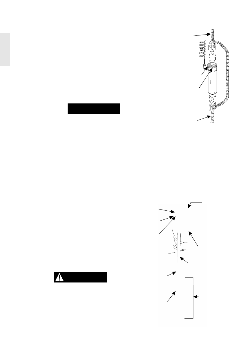
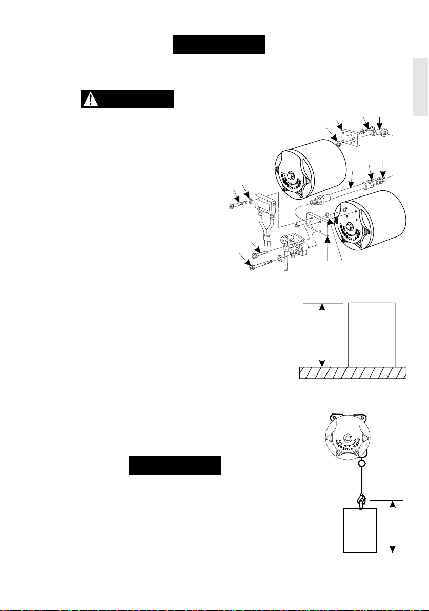
Hook Mounted Load Positioner Installation
Place hook over mounting structure. Make sure hook gate is engaged.
The supporting member should rest completely within the saddle of the hook and be centered directly above
the hook shank. Do not use a supporting member that tilts the unit to one side or the other.
Trolley Mounted Load Positioner Installation
When installing the unit and trolley on the beam, make certain the side plates are parallel and vertical. After
installation, operate the trolley over the entire length of the beam with a capacity load. Ensure rail stops are
installed before operating the unit. Use Grade 5 or better bolts when attaching unit to trolley assembly.
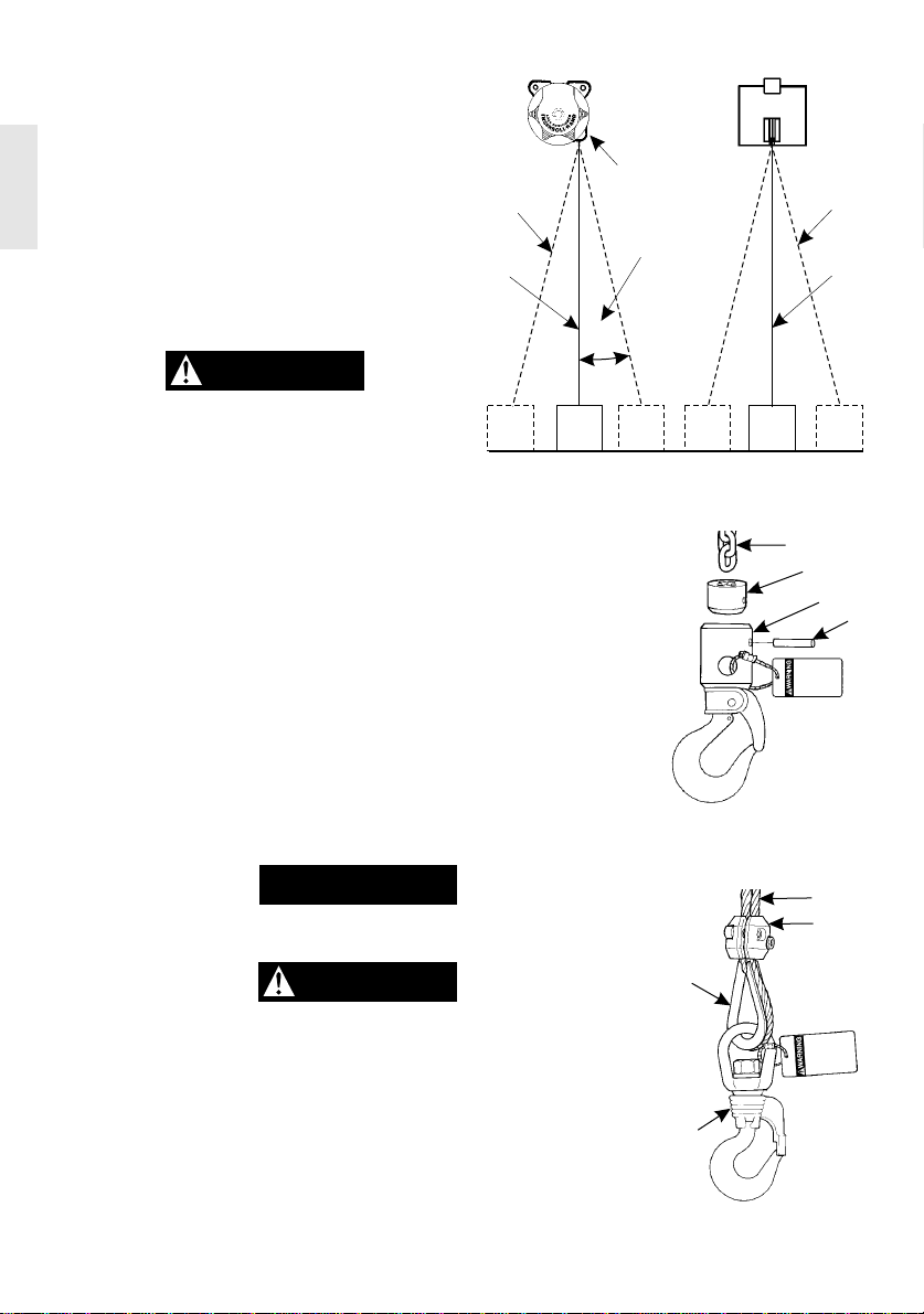
CAUTION
• To avoid an unbalanced load which may damage the trolley, the unit must be centered under the
trolley.
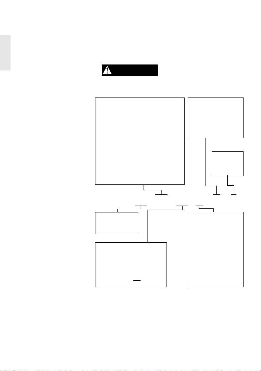
WARNING
•Do not operate with more than 6.9 bar
(100 psi) air pressure.
To Avoid Injury:
•Do not lift more than rated capacities.
•Do not operate with twisted, frayed or
damaged wire rope.
•Do not operate damaged or
malfunctioning positioner.
•Do not lift people or manoeuver loads
over people.
•Do not lift loads that are not centered
under positioner.
•Do not leave a suspended load
unattended.
•Do not attempt to lift a load that is not free
to move.
•Do not attempt to remove load or handling
device until tension is released from chain
or wire rope.
•Do not use a handling device or hook
that does not securely hold the load.
•Do not remove or obscure warning tags.
•Do replace damaged hook or wire rope.
•Do read positioner installation
and operation manual prior to
attempting to adjust or operate
unit.
•Sudden loss of load can result in severe
injury.
2