PART NUMBER FOR ORDERING PART NUMBER FOR ORDERING
5
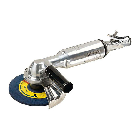
1 Housing 48064. . . . . . . . . . . . . . . . . . . . . . . . . . . .
2 Roll Pin Y178–33. . . . . . . . . . . . . . . . . . . . . . . . . . . . .
3 Lever 48067. . . . . . . . . . . . . . . . . . . . . . . . . . . . . . .
4 Muffler 48171–1. . . . . . . . . . . . . . . . . . . . . . . . . . . . . .
5 Seat 48071. . . . . . . . . . . . . . . . . . . . . . . . . . . . . . .
6 Tip Valve 48070. . . . . . . . . . . . . . . . . . . . . . . . . . .
7 Spring 32858. . . . . . . . . . . . . . . . . . . . . . . . . . . . . .
8‘‘O”Ring Y325–14. . . . . . . . . . . . . . . . . . . . . . . . . . . .
9 Inlet Adapter 48829–1. . . . . . . . . . . . . . . . . . . . . . . .
10 Valve Stem 48065. . . . . . . . . . . . . . . . . . . . . . . . . .
11 Regulator 48068. . . . . . . . . . . . . . . . . . . . . . . . . . .
12 ‘‘O”Ring Y325–13. . . . . . . . . . . . . . . . . . . . . . . . . . . .
13 Retaining Ring Y147–62. . . . . . . . . . . . . . . . . . . . . . .
14 Bracket 48832–1. . . . . . . . . . . . . . . . . . . . . . . . . . . . .
15 Ball Valve 104077–1. . . . . . . . . . . . . . . . . . . . . . . . . . .
16 Adapter 6045. . . . . . . . . . . . . . . . . . . . . . . . . . . . .
17 Barbed Insert 30764. . . . . . . . . . . . . . . . . . . . . . . .
18 Elbow Y229–3. . . . . . . . . . . . . . . . . . . . . . . . . . . . . .
19 Tube 48830–1. . . . . . . . . . . . . . . . . . . . . . . . . . . . . . .
20 Roll Pin Y178–47. . . . . . . . . . . . . . . . . . . . . . . . . . . . .
21 Retaining Ring 44533. . . . . . . . . . . . . . . . . . . . . . .
22 Bearing (2 req’d) 48169–1. . . . . . . . . . . . . . . . . . . . .
23 End Plate (2 req’d) 44529. . . . . . . . . . . . . . . . . . .
24 Cylinder 44531. . . . . . . . . . . . . . . . . . . . . . . . . . . .
25 Blade (5 req’d) 44538. . . . . . . . . . . . . . . . . . . . . . .
26 Rotor 44532–2. . . . . . . . . . . . . . . . . . . . . . . . . . . . . . .
27 Spacer 44878. . . . . . . . . . . . . . . . . . . . . . . . . . . . .
28 Key 39442. . . . . . . . . . . . . . . . . . . . . . . . . . . . . . . .
29 Spindle 48828–1. . . . . . . . . . . . . . . . . . . . . . . . . . . . .
30 Guard 48831–1. . . . . . . . . . . . . . . . . . . . . . . . . . . . . .
31 ‘‘O”Ring Y325–36. . . . . . . . . . . . . . . . . . . . . . . . . . . .
32 Lock Ring 44536. . . . . . . . . . . . . . . . . . . . . . . . . . .
33 Sleeve (not shown) 48073. . . . . . . . . . . . . . . . . . .
DISASSEMBLY/ASSEMBLY INSTRUCTIONS
Always wear eye protection when operating or performing
maintenance on this tool.
Always turn off the air supply and disconnect the air
supply hose before installing, removing or adjusting any
accessory on this tool or before performing any mainte-
nance on this tool.
•Never apply excessive pressure by a holding device which
may cause distortion of a part.
•Apply pressure evenly to parts which have a press fit.
•Apply even pressure to the bearing race that will be press
fitted to the mating part.
•Use correct tools and fixtures when servicing this tool.
•Don’t damage ‘‘O”rings when servicing this tool.
•Use only genuine ARO replacement parts for this tool. When
ordering, specify part number, description, tool model number
and serial number.
MOTOR DISASSEMBLY
–Remove sanding pad.
–Remove inlet adapter (9), releasing bracket (14) and compo-
nents from tool.
–Remove lock ring (32) –LEFT HAND THREADS –‘‘O”ring
(31) and guard (30).
–Remove motor assembly and pin (20). NOTE: It may be nec-
essary to tap housing with a soft face hammer to loosen motor
from housing.
–Remove retaining ring (21).
–Using special brass blocks to fit around o.d. of cylinder, clamp
around cylinder and press shaft of spindle (29) thru bearing
(22) and end plate (23).
–Remove blades (25), rotor (26) and key (28).
–Remove other bearing (22) and end plate (23).
MOTOR ASSEMBLY
–Assemble bearings (22) into end plates (23), pressing on out-
er race of bearings.
–Press one end plate (23), with bearing (22), on shaft of spindle
(29).
–Install key (28) in key slot.
–Assemble rotor (26) to spindle, aligning keyway with key (28).
–Assemble five rotor blades (25) to rotor slots –straight side
out.
–Assemble cylinder (24) over rotor.
–Assemble other end plate (23), with bearing (22), to shaft of
spindle, pressing on inner race of bearing.
–Install retaining ring (21) to groove in spindle, with bow of ring
positioned as shown on parts illustration page.
–Align notches in end plates and cylinder and install roll pin (20)
to notches.
–Assemble motor to housing, aligning pin (20) with groove in
housing.
–Assemble spacer (27) to housing.
–Grease and assemble ‘‘O”ring (31) to lock ring (32).
–Assemble guard (30) over lock ring (32) and thread lock ring
into housing –LEFT HAND THREADS. Tighten securely.
–Assemble bracket (14) and components to tool, inserting tube
(19) thru hole in guard (30).
–Secure bracket with inlet adapter (9).
THROTTLE DISASSEMBLY
–Remove muffler (4).
–Remove inlet adapter (9), releasing bracket (14), ‘‘O”ring (8),
spring (7) and valve (6). NOTE: Do not remove seat (5) unless
damage is evident.
–Remove lock ring (32) –LEFT HAND THREADS –‘‘O”ring
(31) and guard (30).
–Remove retaining ring (13), releasing regulator (11) with ‘‘O”
ring (12) and valve stem (10).
–To remove lever (3), remove roll pin (2).
–Do not disassemble components from bracket (14) unless
damage is evident. To remove ball valve (15), unthread adapt-
er (16) and elbow (18) from ball valve (15). Remove screw and
plastic knob from ball valve to release valve.
–Loosen nut on elbow (18) to remove tube (19).

