manuals.online logo
Brands
  1. Home
  2. •
  3. Brands
  4. •
  5. Ingersoll-Rand
  6. •
  7. Water Pump
  8. •
  9. Ingersoll-Rand ARO EVO EP20-P Series User manual

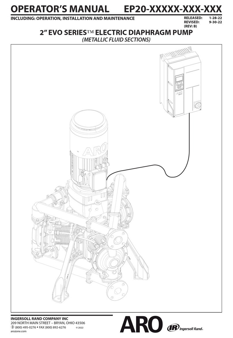
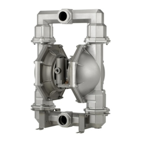
Ingersoll-Rand ARO EVO EP20-P Series User manual

This manual suits for next models

4

Other Ingersoll-Rand Water Pump manuals

Ingersoll-Rand PD15E Series User manual

Ingersoll-Rand

Ingersoll-Rand PD15E Series User manual

Ingersoll-Rand 5696-1 User manual

Ingersoll-Rand

Ingersoll-Rand 5696-1 User manual

Ingersoll-Rand 6662AX-X-C User manual

Ingersoll-Rand

Ingersoll-Rand 6662AX-X-C User manual

Ingersoll-Rand 650770-X-B User manual

Ingersoll-Rand

Ingersoll-Rand 650770-X-B User manual

Ingersoll-Rand ARO 670036-15X User manual

Ingersoll-Rand

Ingersoll-Rand ARO 670036-15X User manual

Ingersoll-Rand ARO PD07 Series User manual

Ingersoll-Rand

Ingersoll-Rand ARO PD07 Series User manual

Ingersoll-Rand ARO PD10 Series User manual

Ingersoll-Rand

Ingersoll-Rand ARO PD10 Series User manual

Ingersoll-Rand NM2C23X-A1-XXX User manual

Ingersoll-Rand

Ingersoll-Rand NM2C23X-A1-XXX User manual

Ingersoll-Rand ARO 66607 A Series User manual

Ingersoll-Rand

Ingersoll-Rand ARO 66607 A Series User manual

Ingersoll-Rand ALBIN PUMP ALP User manual

Ingersoll-Rand

Ingersoll-Rand ALBIN PUMP ALP User manual

Ingersoll-Rand PD10X-X-X User manual

Ingersoll-Rand

Ingersoll-Rand PD10X-X-X User manual

Ingersoll-Rand PH30F-XXX-XXX-C User manual

Ingersoll-Rand

Ingersoll-Rand PH30F-XXX-XXX-C User manual

Ingersoll-Rand 650717-C User manual

Ingersoll-Rand

Ingersoll-Rand 650717-C User manual

Ingersoll-Rand ARO PH10A Series User manual

Ingersoll-Rand

Ingersoll-Rand ARO PH10A Series User manual

Ingersoll-Rand ARO 650442-XXX User manual

Ingersoll-Rand

Ingersoll-Rand ARO 650442-XXX User manual

Ingersoll-Rand ARO 666300 C Series User manual

Ingersoll-Rand

Ingersoll-Rand ARO 666300 C Series User manual

Ingersoll-Rand ARO PD20 Series User manual

Ingersoll-Rand

Ingersoll-Rand ARO PD20 Series User manual

Ingersoll-Rand 66M150-XXX-C User manual

Ingersoll-Rand

Ingersoll-Rand 66M150-XXX-C User manual

Ingersoll-Rand 670053 Series User manual

Ingersoll-Rand

Ingersoll-Rand 670053 Series User manual

Ingersoll-Rand ARO 66605J- Series User manual

Ingersoll-Rand

Ingersoll-Rand ARO 66605J- Series User manual

Ingersoll-Rand PM20R-B02 Series User manual

Ingersoll-Rand

Ingersoll-Rand PM20R-B02 Series User manual

Ingersoll-Rand ARO PP20A Series User manual

Ingersoll-Rand

Ingersoll-Rand ARO PP20A Series User manual

Ingersoll-Rand ARO 612041 Series User manual

Ingersoll-Rand

Ingersoll-Rand ARO 612041 Series User manual

Ingersoll-Rand 637118-C User manual

Ingersoll-Rand

Ingersoll-Rand 637118-C User manual

Popular Water Pump manuals by other brands

Watershed Innovations HYDRAPUMP SMART FLEX Instructional manual

Watershed Innovations

Watershed Innovations HYDRAPUMP SMART FLEX Instructional manual

Graco Modu-Flo AL-5M instructions

Graco

Graco Modu-Flo AL-5M instructions

Messner MultiSystem MPF 3000 operating instructions

Messner

Messner MultiSystem MPF 3000 operating instructions

Xylem Bell & Gossett WEHT0311M Installation, operation and maintenance instructions

Xylem

Xylem Bell & Gossett WEHT0311M Installation, operation and maintenance instructions

WilTec 50739 Operation manual

WilTec

WilTec 50739 Operation manual

Franklin Electric Little Giant 555702 HRK-360S instruction sheet

Franklin Electric

Franklin Electric Little Giant 555702 HRK-360S instruction sheet

VS ZJ Series Operating	 instruction

VS

VS ZJ Series Operating instruction

Flotec FPZS50RP owner's manual

Flotec

Flotec FPZS50RP owner's manual

SKF Lincoln FlowMaster II User and maintenance instructions

SKF

SKF Lincoln FlowMaster II User and maintenance instructions

Xylem Lowara LSB Series Installation, operation and maintenance instructions

Xylem

Xylem Lowara LSB Series Installation, operation and maintenance instructions

Water Duro Pumps DCJ500 Operating & installation instructions

Water

Water Duro Pumps DCJ500 Operating & installation instructions

Action P490 Operating instructions & parts manual

Action

Action P490 Operating instructions & parts manual

Flo King Permacore Reusable Carbon Bag Disassembly. & Cleaning Instructions

Flo King

Flo King Permacore Reusable Carbon Bag Disassembly. & Cleaning Instructions

ARO ARO PD15P-X Operator's manual

ARO

ARO ARO PD15P-X Operator's manual

Pumptec 112V Series Operating instructions and parts manual

Pumptec

Pumptec 112V Series Operating instructions and parts manual

Virax 262070 user manual

Virax

Virax 262070 user manual

Neptun NPHW 5500 operating instructions

Neptun

Neptun NPHW 5500 operating instructions

Sensidyne Gilian BDX-II Operation & service manual

Sensidyne

Sensidyne Gilian BDX-II Operation & service manual

manuals.online logo
manuals.online logoBrands
  • About & Mission
  • Contact us
  • Privacy Policy
  • Terms and Conditions

Copyright 2025 Manuals.Online. All Rights Reserved.

RELEASED: 9-30-22
(REV: A)
INGERSOLL RAND COMPANY INC
209 NORTH MAIN STREET – BRYAN, OHIO 43506
(800) 495-0276 FAX (800) 892-6276 © 2022
arozone.com
OPERATOR’S MANUAL EP20-PXXXX-XXX-XXX
INCLUDING: OPERATION, INSTALLATION AND MAINTENANCE
2” EVO SERIESELECTRIC DIAPHRAGM PUMP
(NON METALLIC FLUID SECTIONS)
Page 2 of 44 EP20-PXXXX-XXX-XXX (en)
TABLE OF CONTENTS
1. TECHNICAL SPECIFICATIONS ................... 3
1.1. Pump Data............................... 3
1.2. Variable Frequency Drive (VFD) Data ...... 3
1.2. Variable Frequency Drive (VFD) Data ...... 4
1.3. Electric Motor Data....................... 5
1.4. Nameplate Details........................ 6
1.4.1 Standard Nameplate ................ 6
1.4.2 Hazardous Nameplate ............... 6
2. MODEL DESCRIPTION CHART. . . . . . . . . . . . . . . . . . . 7
2.1. Model Code Explanation. . . . . . . . . . . . . . . . . . 7
2.2. Encoder Cable Assembly for
Ordinary Motors ......................... 7
3. OPERATING AND SAFETY PRECAUTIONS ........ 8
4. GENERAL DESCRIPTION ........................ 9
4.1. Introduction ............................. 9
4.2. Storage .................................. 9
4.3. Unpacking ............................... 9
5. MECHANICAL INSTALLATION ................... 10
5.1. Pump and Motor Installation ............. 10
5.2. Pump and Gearbox Breather Installation .. 10
5.3. VFD Mechanical installation. . . . . . . . . . . . . . . 11
6. ELECTRICAL INSTALLATION FOR
ORDINARY LOCATIONS......................... 12
6.1. VFD-Wiring Diagram...................... 12
6.2. General Wiring Practice for VFD ........... 12
6.3. VFD AC Mains - Input Power
Requirements: ........................... 13
6.4. Power Wiring............................. 13
6.4.1 VFD - Input Power Wiring ............ 13
6.4.2. VFD - Output Motor Wiring .......... 14
6.4.3. Motor - Input Power Wiring.......... 14
6.5. Control Wiring (Required)................. 15
6.5.1. Leak detector wiring diagram ....... 15
6.5.2. Thermal protection – Ordinary motor 16
6.5.3. Encoder Wiring – Ordinary Motor.... 16
6.6. Control Wiring (Recommended) .......... 17
6.6.1. Safe Stop wiring diagram............ 17
6.7. Control Wiring (Optional) ................. 17
6.7.1. Digital start/ stop control............ 17
6.7.2. Analog Input – Speed control ....... 18
6.7.3. Analog Inputs – Torque (Pressure)
Control ............................. 18
6.7.4. Additional available
Input/output (Optional) ............. 19
6.8. Congured Input / Output Summary -
Ordinary ................................. 19
6.9. VFD serial communication ................ 19
6.10. User dened readout.................... 20
7. ELECTRICAL INSTALLATION FOR
HAZARDOUS LOCATIONS ...................... 21
7.1. General Wiring ........................... 21
7.2. Power Wiring............................. 21
7.3. Control Wiring (Required)................. 21
7.3.1 Leak Detector Wiring ................ 21
7.3.2 Thermal Protection - Hazardous Motor22
7.3.3 Encoder Wiring - Hazardous Motor ... 23
7.4. Control Wiring (Optional) ................. 23
7.5. Congured Input / Output Summary -
Hazardous ............................... 23
7.6. VFD Serial Communication - Hazardous ... 23
8. GROUNDING .................................. 24
8.1. Pump Grounding......................... 24
8.2. VFD Grounding........................... 24
8.3. Electric Motor Grounding................. 24
9. OPERATION.................................... 25
9.1. Pre Operation Checklist................... 25
9.2. Personal Menu Settings .................. 25
9.3. VFD Smart Setup ......................... 26
10. MAINTENANCE ............................... 27
10.1. Service Kits ............................. 27
11. SUBSYSTEM OVERVIEW ....................... 28
11.1. Fluid section ............................ 28
11.2. PRV section ............................. 31
11.3. Crankcase section ....................... 33
11.4. Oil Piston pump section ................. 36
12. TROUBLESHOOTING .......................... 38
12.1 Reset VFD to Factory Default Settings .... 38
13. DIMENSIONAL DATA .......................... 39
13.1 Pump With Motor........................ 39
13.2. Variable Frequency Drive (VFD) .......... 40
14. PERFORMANCE CURVE. . . . . . . . . . . . . . . . . . . . . . . . 42
15. CERTIFICATION ............................... 43
15.1 Certication Standards and Markings .... 43
15.2 Specic Conditions of Use ............... 43
16. WARRANTY DECLARATION .................... 44
EP20-PXXXX-XXX-XXX (en) Page 3 of 44
1. TECHNICAL SPECIFICATIONS
Models......
See Model Description Chart for “-XXXXX”.
Pump Type.. Electric Diaphragm Pump
Material .... See Model Description Chart
Weight (without motor)
EP20-EXXXX-XXX-XXA ............384 lbs (174 kg)
EP20-PXXXX-XXX-XXA............376 lbs (171 kg)
Maximum Material
Inlet Pressure...................
60 psig (4.14 bar)
Minimum Outlet Pressure
@ Deadhead ......................
120 psig (8.3 bar)
Maximum Outlet Working
Pressure ..........................
180 psig (12.4 bar)
Maximum Flow Rate (ooded inlet) ....
140 gpm (530 lpm)
Displacement / Cycle @ 80 psig ...
0.66 gal. (3 lit.)
Maximum Particle Size ...........
1/4”dia. (6.4 mm)
Wet Suction Lift...................
29 ft (8.8 m)
Dry Suction Lift ...................
14 ft (4.3 m)
Maximum Temperature Limits
Min Max Min Max
Ambient Temperature

0
F 104

F
-18
C
40
C
Fluid Temperature
32
F 212

F
0
C
100
C
Fluid temperature should be further limited of one of the following
materials of construction is used in the wetted sections:
PTFE
40
F 212

F
4
C
100
C
Polypropylene
32
F 175

F
0
C
79
C
Conductive Polypropylene
32
F 175

F
0
C
79
C
WARNING
Maximum fluid temperature of 100°C should
never be exceeded to maintain hazardous area surface tempera-
ture nameplate rating.
Dimensional Data......See page 39, 40 and 41
Mounting Dimension ..3 Equally placed
∅0.63”(∅ 16 mm) x
0.94”(24 mm) hole on
∅29.8”(∅ 758 mm) B.C.
1.1. Pump Data
Noise Emission Values in accordance with ISO 4871
Pump conguration EP20-PFPTT-CSV-ACA
(PTFE Balls / Poly Seats)
Sound Power
42 hz (99 rpm) @ 100 psig 83.7 dB(A)
84 hz (198rpm) @ 60 psig 96.2 dB(A)
Sound Pressure
42 hz (99 rpm) @ 100 psig 73.6 dB(A)
84 hz (198rpm) @ 60 psig 86.1 dB(A)
1.2. Variable Frequency Drive (VFD) Data
Ordinary Hazardous
Part Number 136Z7170 136Z7171
Power 7.5 kw 7.5 kw
Input Voltage 380-500 VAC +/-10%, 3 Phase, 50/60 Hz 380-500 VAC +/-10%, 3 Phase, 50/60 Hz
Frame Size A5 A5
Ingress Protection NEMA 4X / IP66 NEMA 4X / IP66
Option A Slot N/A - Available for Fieldbus Card Options MCB 112 PTC THERMISTER CARD
Option B Slot MCB 102 ENCODER CARD MCB 102 ENCODER CARD
Eciency 97% 97%
Approximate Weight 31.5 lbs (14.3 kg) 31.5 lbs (14.3 kg)
Operating Temperature (Full Scale) 32° to 113°F (0 to 45C) 32° to 113°F (0 to 45C)
Operating Temperature (Derate)

14° to 122°F (-10 to 50C) 14° to 122°F (-10 to 50C)
Max Altitude (Without Derating) 3280.8 ft (1000 m) 3280.8 ft (1000 m)
Max Altitude (With Derating) 9842.5 ft (3000 m) 9842.5 ft (3000 m)
Continuous Output Current (380 - 440 V) 16 A 16 A
Intermittent Output Current (380 - 440 V) 25.6 A 25.6 A
Continuous Output Current (441 - 500 V) 14.5 A 14.5 A
Intermittent Output Current (441 - 500 V) 23.2 A 23.2 A
Continuous Input Current (380 - 440 V) 14.4 A 14.4 A
Intermittent Input Current (380 - 440 V) 23.0 A 23.0 A
Continuous Input Current (441 - 500 V) 13.0 A 13.0 A
Intermittent Input Current (441 - 500 V) 20.8 A 20.8 A
Do not allow uids to freeze inside of pump.
When using inlet pressures higher than 10 psig (0.69 bar), the motor torque limit (VFD parameter 416) should be lowered to ensure the pump operates within the published operating map (see
Section 14). The rule of thumb is that the inlet pressure (psig) plus the motor torque limit setting (VFD parameter 416 in %) should equal 115 or less. The formula for this is therefore: [Motor Torque
Limit in %] = [115] – [Inlet Pressure in psig]. For example, an inlet pressure of 40 psig (2.76 bar) requires a motor torque limit of 75% (115 – 40 psig).
Values are determined according to noise test code ISO 20361 using ISO noise measurement standards. Measurement locations of 1m taken at pump/driver midline as per B.3.1 and 6.2 as dened
in standard. Calculated A-weighted sound pressure level using half-spherical surface. Published using uncertainty value of 3.
The 0° to -10° C derating of the VFD is due to the limitation in visibility of the liquid crystal display (LCD). The VFD is capable of operating in temperatures as low as -18° C if running in
"auto on" mode (serial or analog control) and not dependent on the keypad for pump running status or control.
Page 4 of 44 EP20-PXXXX-XXX-XXX (en)
1.2. Variable Frequency Drive (VFD) Data
Ordinary Hazardous
Part Number 132L0263 132L0262
Power 7.5 kw 7.5 kw
Input Voltage 200-240 VAC +/- 10%, 3 Phase, 50/60 Hz 200-240 VAC +/- 10%, 3 Phase, 50/60 Hz
Frame Size B1 B1
Ingress Protection NEMA 4X / IP66 NEMA 4X / IP66
Option A Slot N/A - Available for Fieldbus Card Options MCB 112 PTC THERMISTER CARD
Option B Slot MCB 102 ENCODER CARD MCB 102 ENCODER CARD
Eciency 96% 96%
Approximate Weight 50.7 lbs (23 kg) 50.7 lbs (23 kg)
Operating Temperature (Full Scale) 32° to 113°F (0° to 45°C) 32° to 113°F (0° to 45°C)
Operating Temperature (Derate)

14° to 122°F (-10° to 50°C) 14° to 122°F (-10° to 50°C)
Max Altitude (Without Derating) 3280.8 ft (1000 m) 3280.8 ft (1000 m)
Max Altitude (With Derating) 9842.5 ft (3000 m) 9842.5 ft (3000 m)
Continuous Output Current (200-240V) 30.8 A 30.8 A
Intermittent Output Current (200-240V) 49.3 A 49.3 A
Continuous Input Current (200-240V) 28.0 A 28.0 A
Intermittent Input Current (200-240V) 44.8 A 44.8 A
Ordinary Hazardous
Part Number 132X6019 132X6020
Power 7.5 kw 7.5 kw
Input Voltage 525-600 VAC +/- 10%, 3 Phase, 50/60 Hz 525-600 VAC +/- 10%, 3 Phase, 50/60 Hz
Frame Size A5 A5
Ingress Protection NEMA 4X / IP66 NEMA 4X / IP66
Option A Slot N/A - Available for Fieldbus Card Options MCB 112 PTC THERMISTER CARD
Option B Slot MCB 102 ENCODER CARD MCB 102 ENCODER CARD
Eciency 97% 97%
Approximate Weight 31.5 lbs (14.3 kg) 31.5 lbs (14.3 kg)
Operating Temperature (Full Scale) 32° to 113°F (0° to 45°C) 32° to 113°F (0° to 45°C)
Operating Temperature (Derate)

14° to 122°F (-10° to 50°C) 14° to 122°F (-10° to 50°C)
Max Altitude (Without Derating) 3280.8 ft (1000 m) 3280.8 ft (1000 m)
Max Altitude (With Derating) 9842.5 ft (3000 m) 9842.5 ft (3000 m)
Continuous Output Current (525-550V) 11.5 A 11.5 A
Intermittent Output Current (525-550V) 18.4 A 18.4 A
Continuous Output Current (551-600V) 11.0 A 11.0 A
Intermittent Output Current (551-600V) 17.6 A 17.6 A
Continuous Input Current (525-600V) 10.4 A 10.4 A
Intermittent Input Current (525-600V) 16.6 A 16.6 A
For more details, refer to the VFD manual PN 97999-1940.
The 0° to -10° C derating of the VFD is due to the limitation in visibility of the liquid crystal display (LCD). The VFD is capable of operating in temperatures as low as -18° C if running in
"auto on" mode (serial or analog control) and not dependent on the keypad for pump running status or control.
EP20-PXXXX-XXX-XXX (en) Page 5 of 44
1.3. Electric Motor Data
ORDINARY HAZARDOUS
Part Number 67559 67560-3
Rated Power 5.5 kw 5.5 w
Rated Torque 36 Nm 36 Nm
Eciency IE3 IE3
Number Of Phases 3 3
Polarity 4P 4P
Voltage 230 VD / 400VY 230 VD / 400VY
Frequency 50 Hz 50 Hz
Index Of Protection IP66 IP66
Insulation Class F F
Encoder Type Incremental Incremental
Encoder Characteristics 5V, RS422 (TTL), 1024 PTS 5V, RS422 (TTL), 1024 PTS - IP66 / 67
Encoder Connection 12 Pin connector 10 m cable - ying leads
Drain Plug Position Drive end with plug N/A
Thermal Protection 2 Pto sensors in series 3 Ptc sensors in series
Approx. Weight 236 lbs (107 kg) 304 lbs (138 Kg)
Exact Ratio 12.7 12.7
Output Shaft Spline Spline
Lubricant Type PAO ISO VG 150 PAO ISO VG 150
Lubricant Qty 4.5 Liters (pre-lled) 4.8 Liters (pre-lled) + 1 Liter Container
Main Cable Gland Type 2 x m25 + 1 x m16 with plugs 1 x m25 + 1 x m20 with plugs
Lifting Point 4 x Lifting eye - Casted 4 x Threaded holes - 3 x Lifting eye tted
ORDINAR
Y LOCATION MOTOR
(Black)
HAZARDOUS LOCATION MOTO
R
(Red)
Figure 1
Page 6 of 44 EP20-PXXXX-XXX-XXX (en)
1.4. Nameplate Details
Items supplied vary according to product conguration.
Make sure that the items supplied and the information on the nameplate correspond to the order conrmation.
1.4.1 Standard Nameplate
SERIAL NO
AVG W.P. 
AMBIENT TEMP
98179
ARO EVO SERIES
psig bar
ASSEMBLED INUSA
MFGR DATE
MAX W.P. psig bar
arozone.com
US: Bryan, OH 43506
EU: Lakeview Dr, IE Swords
PUMP MODEL
-18C TO 40C
1.4.2 Hazardous Nameplate
PUMP MODEL

SERIAL NO.

INPUT POWER

Tamb

209. N Main Street, Bryan, OH 43506
98229
CLASS 1 ZONE 1AEx db IIB T4 Gb
ZONE 21AEx tb IIIC T135°C Db
CLASS I DIV 2 GROUPS C-D T4
CLASS II DIV 2 GROUPS F-GT135°C
0123
II 2G Ex h IIB T4 Gb
II 2D Ex h IIIC T135°C Db
TPSATEX 22 XXXXX XXXX X
Ex 60079-46 IIB T4 Gb
Ex 60079-46 IIIC T135°C
Ex h IIB T4 Gb
Ex h IIIC T135°C
IECEx TPS 22.00XX X
-18°C TO +40°C
NRTL
Approval
Pending
Denitions
1. Pump Model - Congured Pump Model Number
2. Assembled In - Country of Assembly
3. Serial Number - Serial Identication Number
4. MGFR Date - Date of Manufacture
5. AVG W.P - Average Pump Working Pressure (Occurs at or near deadhead)
6. Max W.P. - Maximum Pump Working Pressure
7. Ambient Temp - Allowable Ambient Temperature Range
8. Input Power - Allowable input power for VFD
Viton® is a registered trademarks of the Chemours Company Loctite® is a registered trademark of Henkel Corporation 
Santoprene® is a registered trademark of Celanese ARO® is a registered trademark of Ingersoll-Rand Company 
EP20-PXXXX-XXX-XXX (en) Page 7 of 44
2. MODEL DESCRIPTION CHART
2.1. Model Code Explanation
EP -
20 XX
Wetted Parts
E -
XXX-
XXXXXXX
-
P - Polypropylene
Conductive Polypropylene
Port
F - ANSI / DIN Hybrid Flange
Ball
Diaphragms
Bellows
V - Viton®
NOTICE: All possible options are shown in the chart, however, certain combinations may not be recommended.
Consult a representative or the factory if you have questions concerning availability.
Special Testing
Pumps requiring special tests will have a separate line item on the Purchase Order
Motor
A - Santoprene®
A - Santoprene®
VFD Options
A - Revision
Revision
Seat
H - 440 SST
Pump Crank case
C - Cast Iron
S - Integrated Spline Shaft
Pump Input Shaft
P - Polypropylene
S - 316 SST
S - 316 SST
V - Viton®
T - PTFE
T - PTFE
0 - No Motor
A - Ordinary Location Motor
B - Hazardous Location Motor (IECEx, ATEX, NEC, CEC)
0 - None
A - 200 - 240V, 50/60 Hz, Ordinary Drive
C - 380 - 500V, 50/60 Hz, Ordinary Drive
D - 380 - 500V, 50/60 Hz, Hazardous Drive
E - 525 - 600V, 50/60 Hz, Ordinary Drive
F - 525 - 600V, 50/60 Hz, Hazardous Drive
200 - 240V, 50/60 Hz, Hazardous DriveB -
2.2. Encoder Cable Assembly for Ordinary Motors
Each pump with an ordinary location motor comes with a 9 meter encoder cable assembly. Alternate encoder cable assembly
lengths are available through aftermarket.
This shielded cable assembly connects to the 12-pin encoder connector on the motor and the MCB 102 encoder card in the
VFD. For installation instructions, see section 6.5.3.
Part Number (PN) Description Availability
67561-003 Ordinary Motor Encoder Cable Assembly (3 m) Aftermarket
67561-006 Ordinary Motor Encoder Cable Assembly (6 m) Aftermarket
67561-009 Ordinary Motor Encoder Cable Assembly (9 m) Standard - Included with each ordinary location pump
67561-015 Ordinary Motor Encoder Cable Assembly (15 m) Aftermarket
67561-050 Ordinary Motor Encoder Cable Assembly (50 m) Aftermarket
67561-100 Ordinary Motor Encoder Cable Assembly (100 m) Aftermarket
Page 8 of 44 EP20-PXXXX-XXX-XXX (en)
3. OPERATING AND SAFETY PRECAUTIONS
READ, UNDERSTAND, AND FOLLOW THIS INFORMATION TO AVOID INJURY AND PROPERTY DAMAGE.
EXCESSIVE FLUID PRESSURE
STATIC SPARK
HAZARDOUS MATERIALS
HAZARDOUS PRESSURE
WARNING
STATIC SPARK. Can cause explosion re-
sulting in severe injury or death. Ground pump and
pumping system.
Sparks can ignite ammable material and vapors.
The pumping system and object being sprayed must
be grounded when it is pumping, ushing, recirculat-
ing or spraying flammable materials such as paints,
solvents, lacquers, etc. or used in a location where
surrounding atmosphere is conducive to spontaneous
combustion. Ground the dispensing valve or device,
containers, hoses and any object to which material is
being pumped.
Secure pump, connections and all contact points to
avoid vibration and generation of contact or static
spark.
Consult local building codes and electrical codes for
specic grounding requirements.
After grounding, periodically verify continuity of
electrical path to ground. Test with an ohmmeter from
each component (e.g., hoses, pump, clamps, contain-
er, spray gun, etc.) to ground to ensure continuity.
Ohmmeter should show 0.1 ohms or less.
Submerse the outlet hose end, dispensing valve or de-
vice in the material being dispensed if possible. (Avoid
free streaming of material being dispensed.)
Use hoses incorporating a static wire.
Use proper ventilation.
Keep inammables away from heat, open ames and
sparks.
Keep containers closed when not in use.
WARNING
Excessive fluid pressure developed by
pump can cause personal injury, pump damage or
property damage.
Fluid pressure developed by the pump do not exceed
the maximum as stated on the pump model plate.
Be sure material hoses and other components are
able to withstand fluid pressures developed by this
pump. Check all hoses for damage or wear. Be certain
dispensing device is clean and in proper working con-
dition.
WARNING
INSTALLATION OF ELECTRICAL COMPO-
NENTS FOR HAZARDOUS DUTY APPLICATIONS.
Pumps that will operate in environments defined as
“hazardous locations”must only be installed, connect-
ed and set-up by qualied personnel with knowledge
and understanding of protection classes, regulations
and provisions for apparatus in hazardous areas, for
the region where the pump will operate, because
these regulations and provisions, along with the de-
nition of what constitutes hazardous areas vary by
location.
WARNING
ELECTRIC SHOCK HAZARD. This equip-
ment must be grounded. Improper grounding, setup,
or usage of the system can cause electric shock.
Turn o and remove power before disconnecting any
cables and before servicing or installing equipment.
Connect only to grounded power source.
All electrical wiring must be done by a qualied elec-
trician and comply with all local codes and regula-
tions. For North America hazardous locations (NEC/
CEC), ensure wiring is done by a qualied and certied
electrician according to NFPA 70 and CSA C22.1. In-
stallation personnel should meet IEC 60079-14 Annex
A for knowledge, skills and competencies of responsi-
ble persons, operators, technicians and designers.
The knowledge, skills and competences for mainte-
nance and inspection personnel must comply with IEC
60079-17.
The knowledge, skills and competences for repair and
overhaul personnel must comply with IEC 60079-19.
Refer to VFD label and manual for minimum capacitor
discharge time prior to any service.
WARNING
HAZARDOUS PRESSURE. Can result in
serious injury or property damage. Do not service or
clean pump, hoses or dispensing valve while the sys-
tem is pressurized.
Disconnect and lockout / tagout power supply to elec-
tric motor and VFD. Relieve pressure from the system
by opening dispensing valve or device and / or care-
fully and slowly loosening and removing outlet hose
or piping from pump.
WARNING
HAZARDOUS MATERIALS. Can cause se-
rious injury or property damage. Do not attempt to
return a pump to the factory or service center that
contains hazardous material. Safe handling practices
must comply with local and national laws and safety
code requirements.
Obtain Material Safety Data Sheets on all materials
from the supplier for proper handling instructions.
WARNING
EXPLOSION HAZARD. Models containing
aluminum wetted parts cannot be used with 1-1-1
-Trichloroethane,Methylene Chloride or other Halo-
genated Hydrocarbon solvents which may react and
explode.
Check pump crankcase section, PRV section, Oil mod-
ule section, uid caps, manifolds and all wetted parts
to assure compatibility before using with solvents of
this type.
WARNING
MISAPPLICATION HAZARD. Do not use
models containing aluminum wetted parts with food
products for human consumption. Plated parts can
contain trace amounts of lead.
CAUTION
Verify the chemical compatibility of the
pump wetted parts and the substance being pumped,
flushed or recirculated. Chemical compatibility may
change with temperature and concentration of the
chemical(s) within the substances being pumped,
flushed or circulated. For specific fluid compatibility,
consult the chemical manufacturer.
CAUTION
HOT SURFACE. Metallic wetted sections
can reach up to the same temperature as the fluid
temperature (up to 100°C). Precautions should be
taken to restrict access to hot surfaces when needed.
Proper personal protective equipment (PPE) for hot
surfaces should be worn. Check to ensure parts have
cooled down suciently prior to any maintenance.
EP20-PXXXX-XXX-XXX (en) Page 9 of 44
CAUTION
Maximum temperatures are based on
mechanical stress only. Certain chemicals will signi-
cantly reduce maximum safe operating temperature.
Consult the chemical manufacturer for chemical com-
patibility and temperature limits. Refer to PUMP DATA
on page 3 of this manual.
CAUTION
Be certain all operators of this equipment
have been trained for safe working practices, under-
stand it’s limitations, and wear safety goggles / equip-
ment when required.
CAUTION
Do not use the pump for the structural
support of the piping system. Be certain the system
components are properly supported to prevent stress
on the pump parts.
Suction and discharge connections should be flexi-
ble connections (such as hose), not rigid piped, and
should be compatible with the substance being
pumped.
CAUTION
Prevent unnecessary damage to the
pump. Do not allow pump to operate when out of ma-
terial for long periods of time.
Disconnect power supply from motor when system
sits idle for long period of time.
CAUTION
Use only genuine ARO replacement parts
to assure compatible pressure rating and longest ser-
vice life.
NOTICE
TORQUE ALL FASTENERS BEFORE OPER-
ATION. Creep of housing and gasket materials may
cause fasteners to loosen. Torque all fasteners to en-
sure against uid or air leakage.
WARNING
=Hazards or unsafe practices which could
result in severe personal injury, death or
substantial property damage.
CAUTION
=Hazards or unsafe practices which could
result in minor personal injury, product
or property damage.
NOTICE
=Important installation, operation or
maintenance information.
4. GENERAL DESCRIPTION
4.1. Introduction
The EVO Series electric diaphragm pump offers a unique
combination of benets in the positive displacement pump
market. It features a broad range of material compatibility
options, high volume delivery, secondary containment, the
ability to fully deadhead, and is ecient and intelligent. The
pump works on the principle of converting rotary motion
from an AC induction motor to linear reciprocating motion to
drive a diaphragm. The motor is coupled directly to a rotating
eccentric crankshaft to drive connecting rods and pistons
which in turn drive three independent diaphragms. Three
diaphragms are used to ensure reduced pulsation and noise
for smoother and more reliable ow. Pump cycling will begin
as a commanded speed is supplied to the variable frequency
drive (VFD). As back pressure builds, the pump will reduce
speed until maximum line pressure is reached (dispensing
device closed). The pump will resume ow as back pressure is
relieved.
4.2. Storage
Place the equipment in a clean dry area, protected from
impacts, vibrations, temperature extremes and in an environ-
ment with relative humidity less than 90%.
When storing for longer than six months, consult the manu-
facturer.
4.3. Unpacking
Items supplied vary according to product conguration.
Make sure that the items supplied and the information on the
nameplate correspond to the order conrmation.
Check the individual packaging and the product visually for
damage caused by inappropriate handling during shipment.
NOTE: In-case of damage, report the damage to the transport
company and thereafter contact IR distributor.
NOTICE
To protect consumer rights please keep the Label intact on the
Motor, Pump and Drive.
Page 10 of 44 EP20-PXXXX-XXX-XXX (en)
5. MECHANICAL INSTALLATION
5.1. Pump and Motor Installation
WARNING
Pump and motors are industrial products. They
must therefore be installed by qualied, experienced and autho-
rized personnel. The safety of people, animals and property must
be ensured when tting the motors into pump.
CAUTION
Prior to commissioning for all motors, rotate
the motor at no load (no mechanical load) for 2 to 5 minutes,
checking that there is no abnormal noise. If there is any abnormal
noise, see section 5 on motor manual (Page 18).
WARNING
Before starting the motor, it is advisable to
check the insulation between the phases and earth, and between
phases.
Once Pump has been fully unpackaged and inspected, use
lifting points on Crankcase to move into nal operating posi-
tion (See Figure. 2).
Ensure straps and lifting device are properly rated. Refer
section 1.1 for pump weight.
All three lifting points should be used for stability.
Lifting points on Crankcase are intended to only move
the pump.
Do not use pump Manifolds to lift the equipment.
Ensure installation location has enough overhead room
to install motor vertically from above.
Ensure adequate clearance around pump for sufficient
access and ventilation.
Ensure the pump is installed on at level surface.
Secure pump legs to oor with M14 anchors.
Refer to section 13.1 for bolt circle spacing.
Pump must be positioned such that fluid inlet and fluid
outlet port are easily accessible.
Install motor onto the pump crank case.
Ensure gearbox motor does not damage pump Manifolds.
Refer to electric motor manual for lifting points and rec-
ommendations.
Ensure motor is vertical with shaft pointing downward
when mounting to the pump.
Ensure pump Crankshaft is greased from factory.
Motor should be carefully lowered while gently rotating
back and forth to ensure proper engagement of spline
interface. Ensure motor is aligned vertically. Do not apply
excessive force on the pump input Crankshaft. Spline in-
terface will t together easily with proper alignment.
Secure gearbox ange to Crankcase ange with 4X M12 (192)
bolts.
Figure 2
5.2. Pump and Gearbox Breather Installation
Once the motor is in place, the oil breather will need to be
installed in the upper cap of the pump Crankcase.
The pump Crankcase will come pre-lled with oil.
Remove temporary shipping plug (orange) from the
breather port in upper cap of the Crankcase housing.
Remove the plastic elbow (127) and breather (126) se-
cured to one of the pump legs.
Install the plastic elbow until NPT connection is 1-2 turns
from hand-tight with the outlet of the elbow pointing up-
wards.
Install breather onto elbow such that it is in the vertical
orientation.
Sight Glass
Breather
Drain Plug
Figure 3
VFD Mechanical installation
Refer to section 3 of VFD manual for detailed mechanical
installation.
Do not remove the nameplate from the drive.
Ensure that the lifting device is suitable for the task.
Mount drive to a flat surface or ensure back plate is in-
stalled to allow adequate air ow across cooling ns.
Refer to section XX for VFD mounting dimension.
4” (100 mm)
FOR AIR FLOW
4” (100 mm)
FOR AIR FLOW
AIR FLOWAIR FLOW