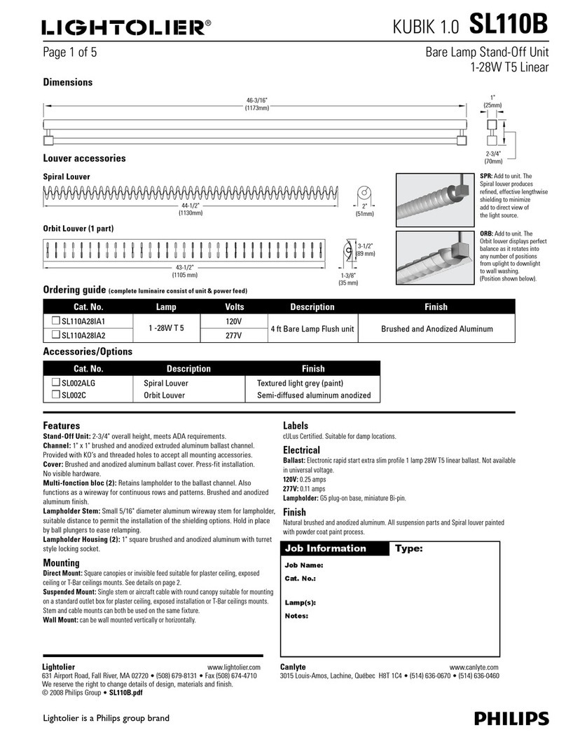
Ingo Maurer Lucellino User manual

Instructions
Lucellino

3
Deutsch Seite 4
English Page 9
Français Page 14
Italiano Pagina 19
Zeichnungen Seite 25
Drawings Page 25
Dessins Page 25
Disegni Pagina 25
2
Montageanleitung
Bitte vor der Montage aufmerksam lesen und
aufbewahren!
Mounting Instructions
Please read the following carefully before use, and
keep the leaflet in a safe place for future reference.
Instructions de montage
Avant le montage veuillez lire attentivement les
instructions et les conserver!
Istruzioni di montaggio
Prima del montaggio, leggere attentamente le
istruzioni e conservarle!

5
Deutsch
4
Deutsch
Lucellino ist eine Niedervolt-Leuchte und benötigt einen
Transformator. Sie können Lucellino einzeln, in einer
Rasteranordnung oder in kleinen Gruppen, auch dicht
nebeneinander, montieren.
Montagevarianten
Lucellino wird in zwei Ausführungen geliefert:
Version A: Aufputzmontage – Transformator und
Zuleitungen bleiben sichtbar.
• mit Transformator Touch Tronic (schalt- und dimmbar nur
an der Lampe).
• mit Transformator Touch Tronic mit Startschaltung (für Steck-
dosen, die über Lichtschalter geschaltet werden können).
• mit Transformator mit Schieberegler.
Version B: Unterputzmontage - direkt auf eine Unter-
putzdose mit bereits vorhandener oder zu installierender
24-Volt-Zuleitung. Transformator und Zuleitung sind
nicht sichtbar, z. B. in einer Hohlwand (mit ausreichender
Belüftung!), installiert. Diese Version ist geeignet für
Gruppeninstallationen über einen Sammeltrafo.
Version B: Transformator, Verkabelung
Der Netzanschluß (230/125 Volt) muss durch einen kurz-
schlußfesten Sicherheitstransformator auf 24 Volt reduziert
werden, der den Vorschriften nach VDE 0551 entspricht.
Lassen Sie sich im Fachhandel beraten und beauftragen Sie
gegebenenfalls einen Elektriker mit der Auswahl und Montage.
Entnehmen Sie bitte aus der Tabelle „Wichtige Installa-
tionshinweise für Niedervolt-Lampen“ am Ende dieser
Anleitung Planungshinweise für die Montage des Trans-
formators sowie die erforderlichen Kabelquerschnitte für
eine korrekte Verkabelung.
Wichtig: Lucellino wird mit einer Spannung von 24 Volt
betrieben: Die Lampe nie direkt an Netzspannung
(230 volt/125 volt) anschließen!
Version A - Aufputzmontage
mit Transformator Touch Tronic oder
Transformator mit Schieberegler
Wichtig: Falls die Lampe mit dem Transformator-Sensor-
Dimmer Touch Tronic ausgestattet ist, beachten Sie bitte
die beiliegende Information, insbesondere den Abschnitt
„Anschließen der Lampe“.
Achtung: Achten Sie auf den Verlauf von Elektroleitungen,
damit auf keinen Fall ein Kabel angebohrt wird. Beachten
Sie, dass die Bohrungen eine Höhe von 240 cm nicht
überschreiten, damit der Transformator auf dem Boden
aufliegt. Bedenken Sie wegen der Kabellänge auch die
maximale Entfernung zu einer Steckdose.
Schließen Sie den Transformator erst nach beendeter
Montage an das Netz an.
Montagevorbereitung
Bohren Sie ein Dübelloch Ø 6 mm. Setzen Sie den Dübel
S6 (1) ein und befestigen Sie die Montageplatte (2) mit
der beiliegenden Schraube (3).
Montage
Stecken Sie die beiden Niedervoltstecker (4) in die Buchsen
der Montageplatte (2), wie in der Zeichnung gezeigt. Bitte
achten Sie auf festen Sitz beider Stecker. Führen Sie die
weiße Abdeckscheibe (5) über Messingbolzen (6) und
Kontaktbuchse (7).
Version B - Unterputzmontage mit einer
bereits vorbereiteten 24-Volt-Zuleitung
Die Montage und der Elektroanschluss sind von einer
Elektrofachkraft auszuführen.
▲
▲
1
2
2
▲

7
Deutsch Deutsch
6
Achtung: Die Montage nur im spannungsfreien Zustand
durchführen, auch wenn es sich hier um eine Niedervolt-
Installation handelt.
Montagevorbereitung
Lösen Sie die beiden Schlitzschrauben (8) der Unterputz-
dose (9) um etwa 5 mm. Lassen Sie die abgemantelten
Transformatorzuleitungen (10) etwa 5 cm aus der Dose
ragen und isolieren Sie die Enden jeweils ca. 5 mm ab.
Nehmen Sie die Lampe und lassen Sie die weiße Abdeck-
scheibe (5) auf den Messingdraht gleiten.
Montage
Halten Sie die Metallscheibe (11) mit einer Hand und
schließen Sie die Zuleitungen (10) (Phase, Null-Leiter) in
der Lüsterklemme (12) an. Stecken Sie die Metallscheibe
auf die Schlitzschrauben (8) der Unterputzdose und
drehen Sie sie innerhalb der Langlöcher kurz nach rechts.
Ziehen Sie die Schrauben fest. Führen Sie die weiße Ab-
deckscheibe (5) über Messingbolzen (6) und Kontakt-
buchse (7).
Einsetzen des Leuchtmittels
Wickeln Sie den angelöteten roten Draht (13) vorsichtig
von der Glühlampe und streifen ihn glatt. Führen Sie ihn
durch den Schraubring (14) und schrauben Sie das Leucht-
mittel in die Fassung. Passen Sie bitte den roten Schalt-
draht (mit 1– 2 lockeren Windungen um den Messingdraht)
dem Verlauf des Messingdrahtes an und stecken Sie ihn fest
in die Kontaktbuchse (7) auf der Abdeckscheibe (5).
Wechsel des Leuchtmittels
Achtung: Schalten Sie die Sicherung des Wandauslasses
aus oder ziehen Sie den Netzstecker, und lassen Sie die
Lampe vollständig abkühlen.
Bevor Sie die zu ersetzende Glühlampe abschrauben, ziehen
Sie den roten Draht (13) aus der Kontaktbuchse (7) auf
der Abdeckscheibe (5) und wickeln ihn vom Haltedraht.
Wickeln Sie den angelöteten roten Draht (13) vorsichtig
vom neuen Leuchtmittel und streifen ihn glatt. Führen Sie
ihn durch den Schraubring (14) und schrauben Sie das
Leuchtmittel in die Fassung. Passen Sie bitte den roten
Schaltdraht (mit 1–2 lockeren Windungen um den Messing-
draht) dem Verlauf des Messingdrahtes an und stecken Sie
ihn in die Kontaktbuchse (7) auf der Abdeckscheibe (5).
Pflegehinweis
Die Flügel aus Gänsefedern können vorsichtig mit einem
Pinsel gesäubert werden. Benutzen Sie für die Abdeck-
scheibe, das Kabel und den Trafo ein mildes Reinigungsmittel.
Gegebenfalls können die Flügel mit handelsüblichem Haar-
lack bzw. -spray imprägniert werden.
Technische Daten
230/125 Volt. 24 Volt, 50 Watt, kein Halogen. Sockel E27.
Elektronischer Transformator-Sensor-Dimmer Touch Tronic
oder elektronischer Transformator mit Schieberegler.
Eventuell notwendige Reparaturen dürfen nur von einer
Elektrofachkraft durchgeführt werden.
▲ ▲ ▲
▲
3
4
3
▲
4
▲

English
98
Deutsch
Version B: Wichtige Installationshinweise
für Niedervolt-Lampen
Bei der Installation von Niedervolt-Lampen ist die Positio-
nierung des Transformators wichtig:
1. Der Trafo sollte leicht zugänglich sein, um die Sicherung
problemlos ersetzen zu können. Achten Sie auf ausrei-
chende Belüftung.
2. Um Brummgeräusche zu vermeiden, sollte der Trafo so
montiert werden, dass keine Schwingungen übertragen
werden.
3. Der Trafo sollte möglichst nahe an den Lichtquellen
montiert werden, da bei Niedervolt-Installationen
verhältnismäßig hohe Ströme fließen und somit Kabel-
länge, Kabelquerschnitt und der daraus resultierende
Spannungsabfall eine wichtige Rolle spielen. Der Span-
nungsabfall ist stets mit einer Lichtstromminderung
verbunden, ausserdem ist beim Bemessen des Kabel-
querschnittes die maximal zulässige Strombelastung zu
beachten.
4. Bei Verwendung eines Dimmers ist darauf zu achten,
dass er für den Betrieb mit Trafo geeignet ist. Der Dim-
mer muss dem Transformator vorgeschaltet werden.
Spannung: 24 Volt
2,5 m 5 m 7,5 m 10 m 15 m
0,75 1,5 2,5 2,5 4 50
1,5 2,5 4 6 6 100*
2,5 4 4 6 12,5 150*
* Werden zwei oder mehrere Lampen zusammen geschaltet, so muß die
angegebene Wattleistung mit der Lampenmenge multipliziert werden.
Die Kabelquerschnitte sind entsprechend auszulegen.
Lampen-
leistung
Watt
Kabelquer-
schnitt mm2
Kabellänge
Lucellino is a low-voltage lamp and requires a transformer.
It can be fitted as a single unit or in multiple patterns or
groups.
Installation options
Lucellino is supplied in two alternative versions:
Version A: Surface mounting – transformer and cable
are visible.
• with Touch Tronic transformer (switchable and dimmable
only by touching the lamp itself).
• with Touch Tronic transformer with a start switch (for
switch-operated outlets).
• with transformer with dimmer.
Version B: Concealed mounting – using a buried electrical
socket, e.g. in a cavity wall (N.B.: Check for sufficient venti-
lation!), with an existing or purpose-installed 24 volts
connection. Transformer and cable are no longer visible.
This version is suitable for groups of lights operated via a
single transformer.
Version B: Transformer and wiring
The 230/125 volts mains current has to be reduced to
24 volts, using a short-circuit-proof transformer constructed
in accordance with the requirements of the German safety
standard VDE 0551. Consult your electrical dealer for advice.
In case of doubt, we recommend that you entrust the
selection and installation to a professional electrician.
See the section below headed “Low-voltage halogen
lamps – important points to remember“ for further hints
on installing the transformer and notes on wiring
requirements.
Important: Lucellino can only be operated with a 24 volts
current. Never connect the lamp directly to the mains
current (230/125 volts)!
▲

English
11
English
10
Version A - Surface mounting with Touch
Tronic transformer or transformer with
dimmer
Important: In case the lamp comes with the transformer-
sensor-dimmer Touch Tronic, please observe the enclosed
information, especially the section headed “Connecting up
the lamp”.
Caution: Take care to ascertain the exact layout of the
wiring in the wall, so to avoid drilling into a power cable.
Please note that the maximum height for the drill holes is
240 cm, to allow the transformer to rest on the floor. The
lamp must also be sited close to the nearest power point;
otherwise the cable may be too short.
Do not connect the transformer to the mains supply until
the entire installation procedure is complete.
Preparations for assembly
Drill a 6 mm diameter hole. Insert the S6 plug (1) and
attach the base plate (2) with the screw (3).
Assembly
Plug the two low-voltage connectors (4) into the sockets
on the base plate (2), as shown in the diagram. Ensure that
both connectors are firmly in position. Fit the white cover (5)
over the brass bolt (6) and the contact sleeve (7).
Version B: Concealed installation with
an existing or purpose-installed 24 volts
connection
The lamp assembly and electrical installation must be
carried out by a qualified electrician.
Caution: Ensure that the current is switched off – despite
the low voltage – while carrying out the installation.
Preparations for assembly
Loosen the two screws (8) in the flush-mounting box (9)
by about 5 mm. Remove about 5 cm of the outer covering
from the transformer cable (10) and strip 5 mm from the
ends of the two leads. Now take the lamp and allow the
white cover (5) to slide down onto the brass wire.
Assembly
Hold the metal disc (11) with one hand and connect the
plus and minus leads (10) to the contacts in the terminal (12).
Fit the metal disc on the screws (8) in the flush-mounting
box and fasten the screws by turning them clockwise in the
longitudinal slits. Tighten the screws. Fit the white cover (5)
over the brass bolt (6) and the contact sleeve (7).
Fitting the bulb
Carefully unwrap the soldered red wire (13) from the
bulb and knead it flat. Feed the wire through the socket
ring (14) and screw the bulb into position. Adjust the red
wire so that it follows the path of the brass retaining wire
(threading it once or twice around the latter) and insert
the end firmly in the contact sleeve (7) in the white
cover (5).
Changing the bulb
Caution: Switch off or remove the fuse for the wall
outlet, or remove the mains plug, and allow the lamp to
cool down completely.
▲
▲ ▲
2
1
3
4
2
▲
▲ ▲

English
13
English
12
Current 24 volts
2,5 m 5 m 7,5 m 10 m 15 m
0,75 1,5 2,5 2,5 4 50
1,5 2,5 4 6 6 100*
2,5 4 4 6 12,5 150*
* If two or more lamps are connected to the same input, the stated
wattage has to be multiplied by the number of lamps. The diameter of
the cable must be adjusted accordingly.
Total
wattage
of lamp
Diameter
of cable in mm2
Required
length of cable
Before unscrewing the spent bulb, pull the red wire (13)
out of the contact sleeve (7) on the white cover (5) and
unwind it from the retaining wire.
Carefully unwrap the soldered red wire (13) from the
bulb and knead it flat. Feed the wire through the socket
ring (14) and screw the bulb into position. Adjust the red
wire so that it follows the path of the brass retaining wire
(threading it once or twice around the latter) and insert the
end firmly in the contact sleeve (7) in the white cover (5).
Cleaning
The goose-feather wings can be cleaned carefully with a
soft paintbrush. A mild household cleaning fluid may be
used for the cover, cable and transformer. If necessary, the
wings can be impregnated with ordinary hairspray or hair
lacquer.
Technical specification
230/125 volts. 24 volts, 50 watts, not halogen. E27 socket.
Electronic transformer-sensor-dimmer Touch Tronic or
electronic transformer with dimmer.
Any repairs that may become necessary must be carried
out by a qualified electrician.
Version B: Low-voltage halogen lamps –
important points to remember
When installing low-voltage lamps, the position of the
transformer is a key consideration.
1. The transformer must be easily accessible so that the
fuse can be replaced without difficulty. Remember the
need for good ventilation.
2. To avoid noise irritation, the transformer must be sited
so as to ensure complete freedom from vibration.
3. The transformer should be positioned as close as possible
to the lamp itself, otherwise you may encounter problems
with voltage drop, which reduces the intensity of the light.
Here, the length and thickness of the power cable are
important considerations. When selecting the type of
cable to be used, always take care to ensure that the
diameter is sufficient to cope with the load involved.
4. If you wish to install a dimmer, make sure that it is suit-
able for use in conjunction with a transformer. It must be
connected in series with the transformer.
▲
4
▲

Français
15
Français
14
Lucellino est une lampe basse-tension et nécessite l’utilisation
d’un transformateur. Vous pouvez monter Lucellino seule, en file
ou en petits groupes et même serrées les unes à côté des autres.
Variantes de montage
Lucellino est disponible en deux versions:
Version A: Montage sur crépi – Transformateur et
alimentation restent visibles.
• avec transformateur Touch Tronic (allumage et réglage
par le toucher de la lampe uniquement).
• avec transformateur Touch Tronic avec un dispositif
d’amorçage (pour les prises réglables par l’interrupteur).
• avec transformateur avec variateur manuel d’intensité
lumineuse.
Version B: Montage sous crépi – directement sur un
boitîer sous-crépi avec alimentation 24 volts déjà existante
ou à installer.
Le transformateur et l’alimentation ne sont pas visibles,
installés par exemple dans un mur creux (avec aération
suffisante!). Cette version convient à une installation en
groupes alimentée par un transformateur collectif.
Version B: transformateur, cablage
Le raccordement (230/125 volts) doit etre réduit à 24 volts
au moyen d’un transformateur de sécurité anti court-circuit,
correspondant aux normes VDE 0551. Faites-vous conseiller
dans le commerce spécialisé et chargez au besoin un
électricien du choix et du montage.
Veuillez consulter le tableau „Indications importantes pour
l’installation de lampes halogènes à bas voltage“ à la fin de ces
instructions pour le montage du transformateur ainsi que pour
les sections de câbles nécessaires à un branchement correct.
Important: Lucellino est alimentée par une tension de
24 volts: ne jamais brancher la lampe dirctement à la
tension du secteur (230/125 volts)!
Version A: Montage sur crépi avec trans-
formateur Touch Tronic ou transformateur
avec variateur manuel
Important: Si la lampe est équipée du transformateur-
sensor-dimmer Touch Tronic, veuillez observer l’information
jointe, en particulier le paragraphe concernant le « branche-
ment de la lampe ».
Attention: Il est indispensable de respecter le positionne-
ment des conduites électriques afin d’éviter de percer un
câble électrique! Eviter de percer les trous au-delà d’une
hauteur de 240 cm afin de s’assurer que le transformateur
repose bien sur le sol. En ce qui concerne la longueur du
câble, veuillez considérer également la distance maximum
à la prise de courant.
Ne connecter le transformateur au courant qu’après le
montage complet.
Préparation pour le montage
Percer un trou de Ø 6 mm pour la cheville. Insérer la
cheville S6 (1) et fixer la plaque de montage (2) avec la
vis jointe (3).
Montage
Insérer les deux fiches basse-tension (4) dans les prises de
la plaque de montage (2) comme illustré dans le dessin.
Veiller à la position ferme des deux fiches. Passer la rondelle
blanche de recouvrement (5) par-dessus le goujon en
laiton (6) et la fiche de contact (7).
Version B - Montage sous crépi avec une
alimentation 24 volts déjà existante
Le montage et la connexion éléctrique sont à effectuer
par un életricien qualifié.
▲
▲▲
1
2
2

Français
17
Français
16
Attention: Uniquement effectuer le montage après mise hors
circuit, malgré le fait qu’il s’agisse d’une installation basse-tension.
pour le montage
Défaire les deux vis à fente sur le boitîer sous-crépi d’environ
5 mm. Laisser dépasser les alimentations isolées du trans-
formateur (10) d’environ 5 cm du boitîer et dénuder chaque
fil d’environ 5 mm. Prendre la lampe et faire glisser la
rondelle blanche de recouvrement (5) sur le fil en laiton.
Montage
Maintenir la plaque en métal (11) d’une main et connecter
les alimentations (10) (phase, prise de terre) dans le
domino (12). Enfoncer la plaque en métal sur les vis à
fente (8) du boitîer sous-crépi et la tourner légerement
vers le côté droit dans les trous oblongs. Serrer les vis.
Amener la rondelle blanche de recouvrement (5) par le
goujon en laiton (6) et la fiche de contact (7).
Insertion de l’ampoule
Dérouler le fil rouge soudé (13) avec précaution de l’ampoule
et lisser le fil. Passer le fil à travers l’anneau fileté (14) et
visser l’ampoule dans la douille. Adapter le fil rouge de
contact à la direction du fil en laiton (en le tournant une
à deux fois peu serré autour du fil en laiton) et le fixer
fermement dans la fiche de contact (7) sur la plaque de
recouvrement (5).
Changement de l’ampoule
Attention: Déconnecter le fusible de la sortie électrique
au mur ou débrancher le câble électrique de la prise de
courant et laisser refroidir la lampe complètement.
Avant de dévisser l’ampoule à remplacer, retirer le fil
rouge (13) de la fiche de contact (7) sur la plaque de
recouvrement (5) et le dérouler du fil de maintien.
Dérouler le fil rouge soudé (13) avec précaution de la
nouvelle ampoule et lisser le fil. Passer le fil à travers
l’anneau fileté (14) et visser l’ampoule dans la douille.
Adapter le fil rouge de contact à la direction du fil en laiton
(en le tournant une à deux fois peu serré autour du fil en
laiton) et le fixer fermement dans la fiche de contact (7)
sur la plaque de recouvrement (5).
Indications d’entretien
Nettoyer les ailes en plumes d’oie avec précaution au
pinceau. Utiliser un produit de nettoyage doux pour la
plaque de recouvrement, le câble et le transformateur.
Eventuellement imprégner les ailes avec une laque à
cheveux.
Données techniques
230/125 volts. 24 volts, 50 watts, n’est pas une ampoule
halogène. Douille E27. Transformateur-sensor-dimmer
électronique Touch Tronic ou transformateur électronique
avec variateur, manuel d’intensité lumineuse.
Des réparations éventuellement nécessaires ne sont à
effectuer que par un spécialiste.
Version B: Indications importantes pour
l’installation de lampes à bas voltage
La position du transformateur est importante lors de
l’installation de lampes à bas voltage:
1. Le transformateur doit etre facile d’accès pour permettre
de changer facilement le fusible. L’emplacement doit
également prévoir un refroidissement suffisant.
3
▲
▲
4
3
▲ ▲
▲▲
4

Italiano
18 19
Français
Lucellino è una lampada a basso voltaggio e richiede l’impiego
di un trasformatore. Lucellino può essere montata sola, in
fila o in piccoli gruppi, l’una vicino all’altra.
Varianti di montaggio
Lucellino è disponibile in due versioni:
Versione A: Montaggio alla parete – trasformatore et
linea di alimentazione rimangono visibili.
• con trasformatore Touch Tronic (accensione e variazione
dell’intensità luminosa soltanto toccando la lampada).
• con trasformatore Touch Tronic con dispositivo di accensione
comandata (per prese di corrente azionabili mediante
interruttore).
• con trasformatore con varialuce lineare.
Versione B: Montaggio incassato – direttamente in una
scatola incassata con un’alimentazione 24 volt già predisposta
o da installare.
Il trasformatore e la linea di alimentazione non sono visibili,
e installati ad es. dietro una controparete (con aerazione
sufficiente!). Questa versione è idonea per l’installazione di
più lampade con un trasformatore unico.
Versione B: Trasfomatore, Cablaggio
L’allacciamento alla rete (230/125 volt) richiede una
riduzione a 24 volt mediante un trasformatore di sicurezza
anti-corto circuito corrispondente alle norme VDE 0551.
Fatevi consigliare in un negozio specializzato e, se necessario,
incaricate un elettricista della scelta e del montaggio.
Vi preghiamo di consultare la tabella „Indicazioni importanti
per l’installazione di lampade alogene a basso voltaggio” alla
fine delle presenti istruzioni, che riporta le indicazioni per
il montaggio del trasformatore nonché le sezioni di cavo
necessarie per un cablaggio corretto.
Importante: Lucellino è alimentata con una tensione di
24 volt. Non collegare mai la lampada alla tensione di rete
(230/125 volt)!
▲
2. Pour éviter des bruits de vrombrissement, le transfor-
mateur doit être monté de manière à ne pas transférer
de vibrations.
3. Le transformateur doit être monté aussi près que possible
des sources lumineuses, car les installations à bas voltage
sont soumises à des tensions relativement fortes, donc
la longueur du câble, la section du câble et par conséquent
la baisse de tension jouent un rôle important. La baisse
de tension est toujours liées à une diminution de
l’intensité lumineuse. En outre, pour le calcul de la section
du câble il faut respecter la capacité maximum de courant
autorisée.
4. Lors de l’utilisation d’un variateur il faut veiller à ce qu’il
soit adapté pour un fonctionnement avec un transfor-
mateur. Le variateur doit être couplé avant le transfor-
mateur.
Tension: 24 volts
2,5 m 5 m 7,5 m 10 m 15 m
0,75 1,5 2,5 2,5 4 50
1,5 2,5 4 6 6 100*
2,5 4 4 6 12,5 150*
* Au cas où deux ou plusieurs lampes sont couplées ensemble, la
puissance en watts indiquée doit être multiplée en fonction de la quan-
tité de lampes. Les sections de câbles sont à calculer en conséquence.
Puissance
de lampe
Watts
Section de
câble en mm2
Longueur
de câble

Italiano
21
Italiano
20
Versione A: Montaggio alla parete con
trasformatore Touch Tronic o con tras-
formatore con varialuce lineare
Importante: Nel caso della versione con trasformatore-
sensore-dimmer Touch Tronic, leggere attentamente il foglio
informativo incluso, specialmente il paragrafo „Collegamento
della lampada”.
Attenzione: Fare attenzione alla linea di alimentazione, per
evitare di danneggiare il cavo. Per poter successivamente
posare il trasformatore sul pavimento, i fori non devono
trovarsi a un’altezza superiore a cm. 240. Tenere in con-
siderazione anche la lunghezza del cavo e quindi la distanza
massima dalla presa elettrica.
Collegare il trasformatore alla rete soltano a montaggio
avvenuto.
Preparazione del montaggio
Effettuare un foro per il tassello di Ø mm 6. Inserire il
tassello S6 (1) e fissare la piastra di montaggio (2) con la
vite allegata (3).
Montaggio
Inserire entrambi gli spinotti a bassa tensione (4) nelle prese
della piastra di montaggio (2), come da figura. Assicurarsi
che i due spinotti siano saldamente inseriti. Far passare il
disco di copertura bianco (5) sul perno in ottone (6) sulla
presa di contatto (7).
Versione B - Montaggio incassato con
un’alimentazione 24 volt già predisposta
Il montaggio ed il collegamento elettrico devono essere
eseguiti da un elettricista specializzato.
Attenzione: Anche trattandosi di un’installazione a basso
voltaggio, effettuare il montaggio soltano se la lampada
non è collegata alla rete.
Preparazione del montaggio
Allentare di circa mm. 5 le due viti con taglio piatto (8) della
scatola incassata (9). Lasciare spuntare i cavi di alimentazione
isolati (10) del trasformatore di circa cm. 5 dalla scatola
incassata e spelare le relative estremità di circa mm. 5.
Prendere la lampada e far passare il disco di copertura
bianco (5) sul filo in ottone.
Montaggio
Tenere il disco in metallo (11) con una mano e con l’altra
mano collegare i cavi di alimentazione (10) (fase, neutro)
al morsetto (12). Applicare il disco in metallo sulle viti con
taglio piatto (8) della scatola incassata e girarlo leggermente
verso destra nelle asole. Serrare le viti. Far passare il disco
di copertura bianco (5) sul perno in ottone (6) sulla presa
di contatto (7).
Inserimento della lampadina
Svolgere e poi stendere con cautela il filo rosso (13)
saldato e avvolto intorno alla lampadina. Farlo passare
attentamente attraverso il portalampada (14) e avvitarci la
lampadina. Adattare il filo di collegamento rosso al filo in
ottone (avvolgendolo 1–2 volte intorno al filo in ottone) e
inserirlo saldamente nella presa di contatto (7) sul disco di
copertura (5).
Sostituzione della lampadina
Attenzione: Staccare la corrente oppure staccare la spina
e attendere che la lampada sia completamente fredda.
▲▲
▲▲ ▲
3
4
1
3
▲
2
2

Italiano
23
Italiano
22
Tensione: 24 volt
2,5 m 5 m 7,5 m 10 m 15 m
0,75 1,5 2,5 2,5 4 50
1,5 2,5 4 6 6 100*
2,5 4 4 6 12,5 150*
* Nel caso che due o più lampade siano accese allo stesso tempo, la
potenza indicata in watt deve essere moltiplicata in funzione della
quantità di lampade. Le sezioni dei cavi devono essere calcolate di
conseguenza.
Potenza
lampada
Watt
Sezione
cavi mm2
Lunghezza
cavi
Prima di svitare la lampadina da sostituire, staccare il filo
rosso (13) dalla presa di contatto (7) sul disco di copertura (5)
e scioglierlo dal filo di sostegno.
Svolgere attentamente il filo rosso saldato (13) della nuova
lampadina e stirarlo. Farlo passare con cautela attraverso il
portalampada (14) e avvitarci la nuova lampadina. Adattare
il filo di collegamento rosso al filo in ottone (avvolgendolo
1–2 volte intorno al filo in ottone) e inserirlo saldamente
nella presa di contatto (7) sul disco di copertura (5).
Cura e manutenzione
Le ali di piume d’oca possono essere pulite cautamente
con un pennello. Per il disco di copertura, il cavo e il tras-
formatore usare un prodotto non agressivo. In caso di
necessità, le ali possono essere impregnate con una lacca/spray
per capelli.
Dati tecnici
230/125 volt. 24 volt, 50 watt, non alogena. Base E27.
Trasformatore-sensore-dimmer elettronico Touch Tronic
o transformatore elettronico con varialuce lineare.
Eventuali riparazioni possono essere eseguite
esclusivamente da un elettricista specializzato.
Versione B: Informazioni importanti
per l’installazione di lampade alogene
a basso voltaggio
Nell’installazione di lampade alogene a basso voltaggio è
importante osservare un posizionamento corretto del
trasformatore:
1. Il trasformatore deve essere facilmente accessibile, per
consentire una facile sostituzione del fusibile. Provvedere
a un’aerazione sufficiente.
▲▲
4
2. Per un funzionamento silenzioso del trasformatore, mon-
tarlo in modo che non si possano trasmettere oscillazioni.
3. E’ importante installare il trasformatore il più vicino pos-
sibile alle fonti di luce, visto che le installazioni a basso
voltaggio generano correnti relativamente alte e quindi la
lunghezza e la sezione del cavo, e così la caduta di
tensione, rappresentano un fattore importante. La caduta
di tensione è sempre collegata a una riduzione della
luce. Nel determinare la sezione del cavo, osservare il
carico di corrente massimo consentito.
4. Con impiego di un variatore d’intensità luminosa, con-
trollare preventivamente che sia concepito per l’uso con
trasformatore. Il dimmer deve essere collegato in serie
prima del trasformatore.

25
1

26
13
14
27
3
4
2
24 Volt!
24 Volt!
1
Ø 6 mm
4
7
2
6
5
3
5
10
11
12
8
9
8
6
7
6
7
5

Ingo Maurer GmbH
Kaiserstrasse 47
80801 München
Tel. 089-381606-0
Fax 089-381606 20
Oktober 2000 Made in Germany
Other manuals for Lucellino
2
Table of contents
Languages:
Popular Light Fixture manuals by other brands

AVE
AVE ECLIPSE CLUB 1000MKII user manual
Cooper Lighting
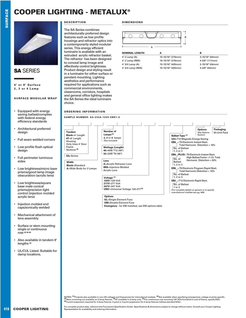
Cooper Lighting Metalux SA SERIES Specifications

Pentair
Pentair 560003 installation instructions

Sagitter
Sagitter ARCHER B2 user manual
Cooper Lighting
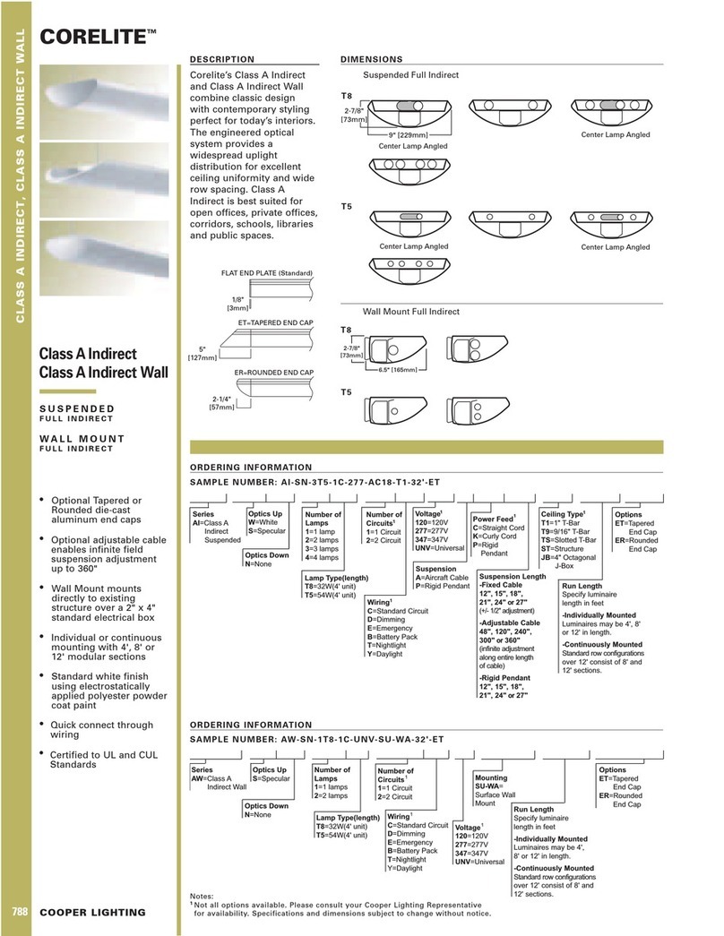
Cooper Lighting CORELITE Indirect Wall Lighting Specifications

The Wand Company
The Wand Company Star Trek Original Series Rock Mood Light manual
RAB Lighting
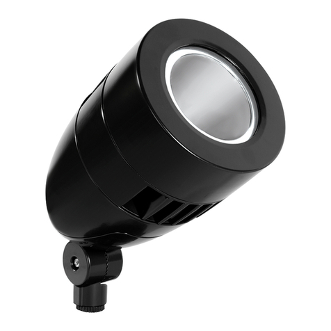
RAB Lighting HSLED installation instructions
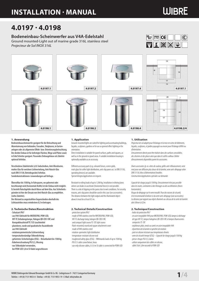
Wibre
Wibre 4.0197 Series installation manual
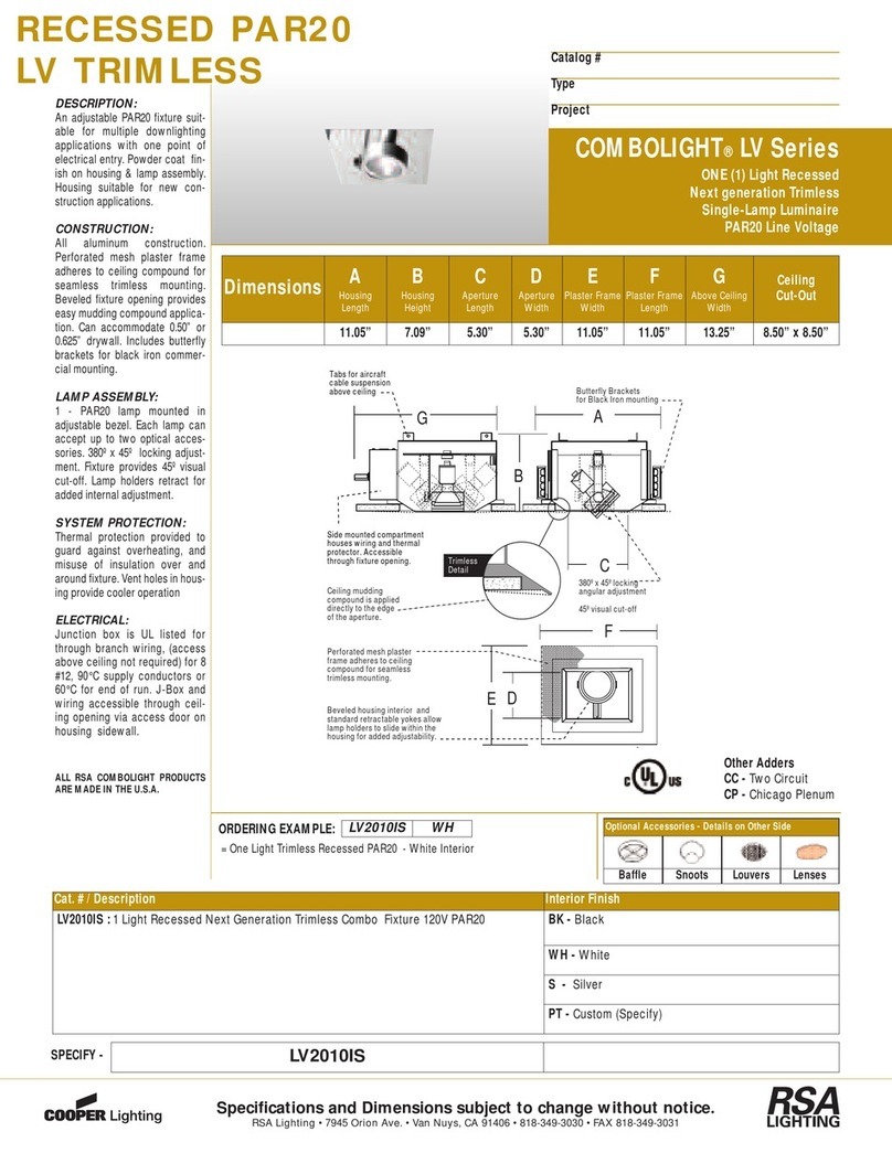
RSA Lighting
RSA Lighting Combolight LV2010IS WH Specifications
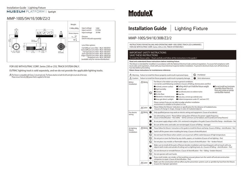
Modulex
Modulex MMP-100S/5H/1E/30B/Z2/2 installation guide
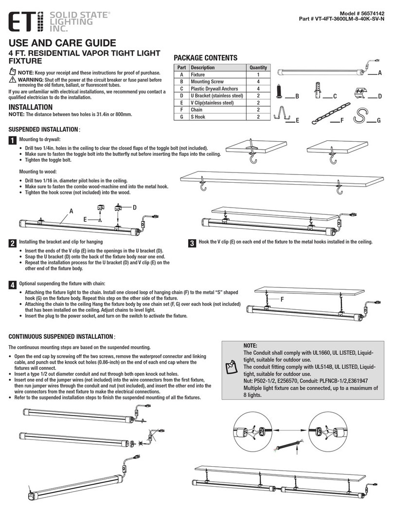
ETI
ETI SOLID STATE 56574142 Use and care guide
Lightolier
Lightolier Lytespan 9170 specification
