Ingun MA 2x09 Series User manual

Technical manual
Manual Test Fixture
MA xxxx with ATS MAxx

Technical manual MA xxxx with ATS MAxx
1 ©INGUN: Subject to technical changes without notice. E&OE.
1Product description.....................................................................................................................4
1.1 MA xxxx .........................................................................................................................................4
1.2 ATS MAxx......................................................................................................................................5
1.2.1 Standard version.............................................................................................................5
1.2.2 ESD version....................................................................................................................5
1.2.3 RF version.......................................................................................................................5
2SAFETY.........................................................................................................................................6
2.1.1 Safety advice for testing with harmless high-voltage......................................................6
2.1.2 Air distance and max. allowable current:........................................................................6
2.1.3 Commissioning of safety functions .................................................................................6
2.1.4 Dangers when operating electromagnets.......................................................................7
3Customising.................................................................................................................................7
3.1 Customising for stroke 22 mm (MA 3xxx)......................................................................................8
3.2 Customising accessories...............................................................................................................8
3.2.1 Interface blocks (SB).......................................................................................................8
3.2.2 Start-up kit (SK) ..............................................................................................................8
3.2.3 Side approach mechanism (SAM)..................................................................................8
3.2.4 Marking units (ME)..........................................................................................................9
3.2.5 Potentiometer screwing unit/key button activators .........................................................9
4Functional sequence...................................................................................................................9
5Additional Functions MAxxxx ..................................................................................................10
5.1 Protection conductor wiring and contact protection for dangerous voltages...............................10
5.2 ESD assembly .............................................................................................................................11
5.3 ESD assembly and protection conductor wiring..........................................................................11
5.4 Dual-stage contacting from bottom side......................................................................................11
5.4.1 Locked electrically.........................................................................................................13
5.4.2 Pneumatic locking.........................................................................................................14
5.4.3 Mechanical stroke limitation..........................................................................................15
5.5 Dual-stage contacting with self-opener .......................................................................................15
5.5.1 Electrical dual-stage contacting with self-opener .........................................................16
5.5.2 Pneumatic dual-stage contacting with self-opener.......................................................16
5.5.3 Mechanical dual-stage contacting with pneumatic self-opener....................................17
6Additional Functions ATS MAxx..............................................................................................18
6.1 ESD version.................................................................................................................................18
6.2 Radio frequency version..............................................................................................................18
7Optional Functions MAxxxx .....................................................................................................20
7.1 Safety switch for closed pressure frame......................................................................................20
7.1.1 Safety switch with locking NO (currentless; open) .......................................................22
7.1.2 Safety switch with locking NC (currentless; closed) .....................................................23
7.1.3 Safety switch without locking........................................................................................23
7.1.4 Magnetic safety switch..................................................................................................24
7.2 Self-opener ..................................................................................................................................24
7.2.1 Pneumatic.....................................................................................................................26
7.2.2 Electric ..........................................................................................................................27
7.3 Check for pressure frame closed.................................................................................................27
7.3.1 Check via stroke switch ................................................................................................27
7.3.2 Check stroke position by inductive sensor ...................................................................28
7.3.3 Check locking position by inductive sensor..................................................................28
7.4 Check ATS locked .......................................................................................................................28
7.5 Locking unit for closed pressure frame........................................................................................29
7.5.1 Stroke magnet NC (currentless; closed).......................................................................29
7.5.2 Stroke magnet NO (currentless; open).........................................................................30

Technical manual MA xxxx with ATS MAxx
©INGUN: Subject to technical changes without notice. E&OE. 2
7.5.3 Pneumatic cylinder locking ...........................................................................................30
7.6 Locking unit for pressure frame open..........................................................................................31
7.7 Pressure frame unit opening limited............................................................................................32
7.8 Upgrade kit gas pressure spring..................................................................................................32
7.9 Gas pressure springs for the drive unit (kit).................................................................................33
7.10 Hinged metal handle....................................................................................................................33
7.11 Pass / fail LED indicator...............................................................................................................34
7.12 Push button..................................................................................................................................34
7.13 Oil break.......................................................................................................................................35
7.14 Anti-pinch protection....................................................................................................................35
7.15 Extended handle..........................................................................................................................35
7.16 MA control unit.............................................................................................................................36
7.17 Magnet control unit ......................................................................................................................38
8Optionally Available ..................................................................................................................39
8.1 Dual-stage upgrade kit.................................................................................................................39
8.2 Reinforcement for customisations with large number of test points............................................40
8.2.1 Stiffener kit for NDH......................................................................................................40
8.2.2 Stiffener kit for KTE.......................................................................................................40
8.3 Insertion blocker for stroke 22mm ...............................................................................................41
8.4 Contact protection for dangerous voltage....................................................................................41
8.5 Lifting units...................................................................................................................................42
8.6 Check for “pressure frame closed” ..............................................................................................43
8.6.1 Check for pressure frame closed using two GKS.........................................................43
8.6.2 Check for pressure frame closed via stroke switch......................................................43
8.7 Actuator for safety switch with and without locking .....................................................................44
8.7.1 Actuator for single-stage...............................................................................................44
8.7.2 Actuator for dual-stage (basic unit)...............................................................................44
8.7.3 Actuator for magnetic safety switch..............................................................................45
8.8 Ground plate for ATS...................................................................................................................45
8.9 Contacting from above (mounting kit)..........................................................................................46
8.9.1 6.9.1 Normal assembly.................................................................................................46
8.9.2 ESD assembly ..............................................................................................................46
9Further maintenance ................................................................................................................46
9.1 ATS mounting check....................................................................................................................46
9.2 Replacement and wear parts MA xxxx........................................................................................47
9.2.1 9.4.1 Gas pressure spring ............................................................................................47
9.2.2 Upgrade bearing bracket set ........................................................................................47
9.3 Replacement and wear parts ATS MAxx.....................................................................................48
9.3.1 Stacking screw..............................................................................................................48
9.3.2 Pressure spring.............................................................................................................48
9.3.3 Wire mesh sealing for RF-ATS.....................................................................................48
9.3.4 Contact spring kit for RF-ATS (previous version).........................................................48
9.3.5 Probe plate (KTP).........................................................................................................48
9.3.6 Moving plate (ADP).......................................................................................................49
9.3.7 Pressure frame plate (NHP) .........................................................................................49
9.3.8 Wiring guard plate (VSP)..............................................................................................49
9.3.9 Knurled-head screw ATS..............................................................................................49
10 Technical Data ...........................................................................................................................50
10.1 Specification of components used...............................................................................................50
10.1.1 Stroke switch (Part number 20202) ..............................................................................50
10.1.2 Inductive sensor (Part number 26466) .........................................................................50
10.1.3 Inductive sensor M8x1 (Part number 33831) ...............................................................50

Technical manual MA xxxx with ATS MAxx
3 ©INGUN: Subject to technical changes without notice. E&OE.
10.1.4 Inductive sensor (Part number 36684) .........................................................................50
10.1.5 Inductive sensor (Part number 38413) .........................................................................50
10.1.6 Inductive sensor (Part number 44833) .........................................................................51
10.1.7 Stroke magnet NC (currentless; closed) (Part number 50856) ....................................51
10.1.8 Stroke magnet NO (currentless; open) (Part number 33491) ......................................51
10.1.9 Valve assembly 3/2-way (Part number 43583).............................................................51
10.1.10 Valve assembly 5/2-way (Part number 42702).............................................................51
10.1.11 Pneumatic cylinder 12-10 (Part number 49273)...........................................................52
10.1.12 Pneumatic cylinder 12-10 (Part number 43251)...........................................................52
10.1.13 Pneumatic cylinder 12-10 (Part number 49273)...........................................................52
10.1.14 Pneumatic cylinder 25-50 (Part number 39203)...........................................................52
10.1.15 Pneumatic cylinder 32-10 (Part number 39673)...........................................................52
10.1.16 Pneumatic cylinder 32-30 (Part number 28235)...........................................................52
10.1.17 Compressed air combination (Part number 14241)......................................................53
10.1.18 Brake cylinder D-040-12-040-123 (Part number 51863)..............................................53
10.1.19 LED SMD strip green (Part number 45673) .................................................................53
10.1.20 LED SMD strip red (Part number 45674) .....................................................................53
10.1.21 Push button yellow (Part number 33466) .....................................................................53
10.1.22 Push button red (Part number 33467)..........................................................................53
10.1.23 Push button green (Part number 33468)......................................................................53
11 Compatibility matrix ..................................................................................................................55
Technical manual MA xxxx with ATS MAxx
©INGUN: Subject to technical changes without notice. E&OE. 4
1 PRODUCT DESCRIPTION
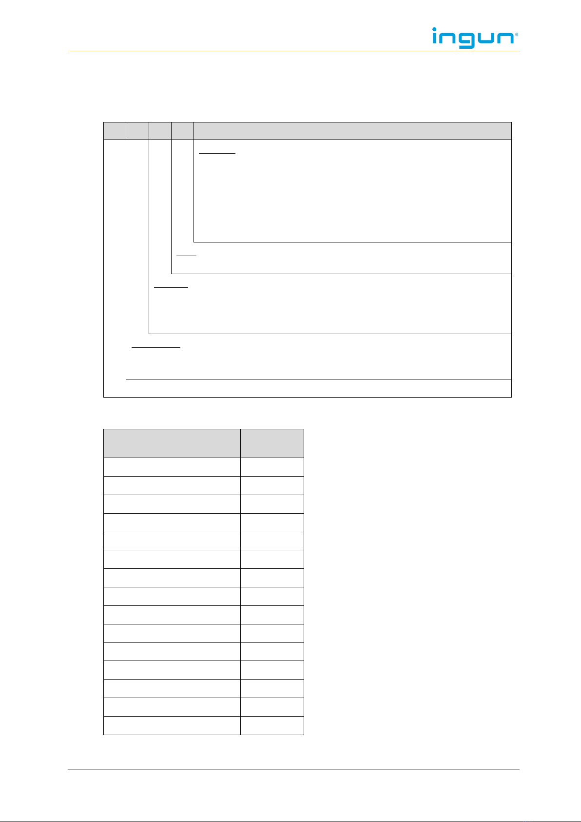
1.1 MA xxxx
Designation convention:
MA
2
1
13
T/D/H/S-10
Options:
T= tandem version
/D = desk (desk housing) / F = flat housing
/H = fixing drive unit H = hinge “ “ = firmly screwed together
/S-n = Number of interface blocks (5 –10 pc.) / “ “ = no interface
/HG = high housing / “ “ = standard housing
/tester-interface: see matrix in test fixture catalogue
size:
09 –14
version:
0without interface
1standard with interface
2heavy-duty version
generation:
2MA with stroke 14mm
3MA with stroke 22mm
manual test fixture
Basic units with internal interface and without test system interface
Description
Part num-
ber
MA 2109/D/H/S-5
34340
MA 2111/D/H/S-5
31730
MA 2111/D/H/S-5/HG
33420
MA 2112/D/H/S-7
32660
MA 2112/D/H/S-7/HG
33460
MA 2113/D/H/S-10
32500
MA 2113/D/H/S-10/HG
32700
MA 2113T/D/H/2xS-5
32300
MA 2113T/D/H/2xS-5/HG
36666
MA 2114/D/H/S-10
34350
MA 3211/D/H/S-5
43950
MA 3212/D/H/S-7
43630
MA 3213/D/H/S-10
43580
MA 3213T/D/H/2xS-5
43970
MA 3214/D/H/S-10
43960
Technical manual MA xxxx with ATS MAxx
5 ©INGUN: Subject to technical changes without notice. E&OE.
1.2 ATS MAxx
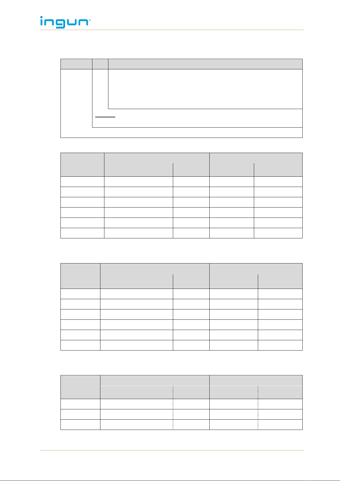
Designation convention:
ATS MA
14
/S-10
Options:
-2 Dual-stage version (only for pneumatic upgrade kit)
/S-n Number of interface blocks (5 –10 pc.) / “ “ = no interface
/ESD ESD version
/RF Radio frequency
/SN Rigid pin
version:
09 –14
Exchangeable kit MA
1.2.1 Standard version
Basic unit
with internal interface
without internal interface
Designation
Part
number
Designation
Part
number
MA 2x09
ATS MA09/S-5
45990-KIT
ATS MA09
45994-KIT
MA xx11
ATS MA11/S-5
45898-KIT
ATS MA11
45900-KIT
MA xx12
ATS MA12/S-7
45903-KIT
ATS MA12
45904-KIT
MA xx13
ATS MA13/S-10
45908-KIT
ATS MA13
45980-KIT
MA xx13T
ATS MA11/S-5
45898-KIT
ATS MA11
45900-KIT
MA xx14
ATS MA14/S-10
45983-KIT
ATS MA14
45985-KIT
The ATS is delivered as a kit and therefore is not mounted.
1.2.2 ESD version
Basic unit
with internal interface
without internal interface
Designation
Part
number
Designation
Part
number
MA 2x09
ATS MA09/S-5/ESD
46233-KIT
ATS MA09
46245-KIT
MA xx11
ATS MA11/S-5/ESD
46026-KIT
ATS MA11
46248-KIT
MA xx12
ATS MA12/S-7/ESD
46236-KIT
ATS MA12
46250-KIT
MA xx13
ATS MA13/S-10/ESD
46239-KIT
ATS MA13
46254-KIT
MA xx13T
ATS MA11/S-5/ESD
46026-KIT
ATS MA11
46248-KIT
MA xx14
ATS MA14/S-10/ESD
46242-KIT
ATS MA14
46257-KIT
The ATS is delivered as a kit and therefore is not mounted (see chapter 6.1, p. 18).
1.2.3 RF version
Basic unit
with internal interface
without internal interface
Designation
Part
number
Designation
Part
number
MA xx11
ATS MA11/S-5/HF
54111
ATS MA11/HF
54011
MA xx12
ATS MA12/S-7/HF
54112
ATS MA12/HF
54012
MA xx13
ATS MA13/S-10/HF
54113
ATS MA13/HF
54013
ATS is delivered mounted (see chapter 6.2, S. 18).

Technical manual MA xxxx with ATS MAxx
©INGUN: Subject to technical changes without notice. E&OE. 6
2 SAFETY
2.1.1 Safety advice for testing with harmless high-voltage
Touching of parts under voltage is regarded as not danger-
ous under the following conditions:
„At voltages with frequencies up to 500 Hz above AC 25V
or DC 60V the evoked current is due to an inductive-free
resistor of 2kOhm not greater than 3mA AC effective re-
spectively 12mA DC “(DIN EN 50191, p.5).
When testing voltages that fulfill these conditions the test
fixture can be operated also with such a high-voltage. How-
ever, special wiring components must be chosen and the wiring must be laid out for the necessary
air- and creep-paths. For this reason the additionally stated high-voltage and the applicable stated
current rating on the type label must not be exceeded.
2.1.2 Air distance and max. allowable current:
The air distance is the shortest gap between two conductive components and decisive for the
max. allowable current of the applied Interface Block pairs. The main rule for the sparkover of
sharp components in the air under standard conditions is:
for each mm distance approx. 0.8 kV.
(Max. allowable current at 170-pole Low Ohm Blocks, for example:
0.34 mm (air distance not wired) * 0.8 kV ≈ 270 V)
2.1.3 Commissioning of safety functions
The test fixture does not have its own control system. Therefore, the commissioning carried out
by the customer also includes the evaluation and control of the safety-relevant switches and sen-
sors. The demands on this part of the control unit are defined in the DIN EN ISO 13849-1 "Safety
of machines; safety-related parts of the control unit –part 1: General design guideline".
According to the risk evaluation carried out by INGUN, the test fixture with pneumatic or electro-
magnetic functions presents the following risk evaluation:
WARNING:DANGER OF INJURY!
Mechanical danger due to moving parts
Risk evaluation (according to DIN EN ISO 13849-1, risk paragraph p. 55):
Severity of the injury
S = S1 minor (normally reversible injury)
Frequency and/or
exposure to hazard
F = F1 seldom to less-frequent and/or expo-
sure to hazard is short
Possibility of avoiding
the danger
P = P2 hardly possible
This leads to a necessary performance level PL of b.
Technical manual MA xxxx with ATS MAxx
7 ©INGUN: Subject to technical changes without notice. E&OE.
Using the test fixture with low-voltage customising the following risk evaluation is given:
WARNING:DANGER OF INJURY!
Electrical dangers due to parts carrying voltage, overload and parts,
that are carrying voltage due to a faulty state
Risk evaluation (according to DIN EN ISO 13849-1):
Severity of the injury
S = S2 serious (normally irreversible injury in-
cluding death)
Frequency and/or
exposure to hazard
F = F1 seldom to less-frequent and/or exposure
to hazard is short
Possibility of avoiding
the danger
P = P2 hardly possible
This leads to a necessary performance level PL of d.
For voltages greater than 240 Volt the wiring must be designed to take the necessary air and
creepage paths into consideration. Therefore, the permitted voltage stated on the label must not
be exceeded at any time.
Necessary additional functions:
Contact protection for dangerous voltage (see chapter 8.4, page 41)
Actuator for safety switch with and without locking (see chapter 8.7, page 44)
2.1.4 Dangers when operating electromagnets
Within some optional functions electromagnets are used to lock specific positions. When operat-
ing electromagnets with nominal voltage for a long time (>10 minutes) their outside get very hot.
The outer surface of electromagnets reaches high temperatures (70°C +) when nominal voltage
is applied for an extended period of time (>10 minutes).
WARNING:DANGER OF INJURY!
Thermal dangers resulting from hot surfaces
The electromagnets can heat up to 70° C when operated for a long time with
full continuous power supply.
The electromagnetic should not be active when the fixture is not being
used.
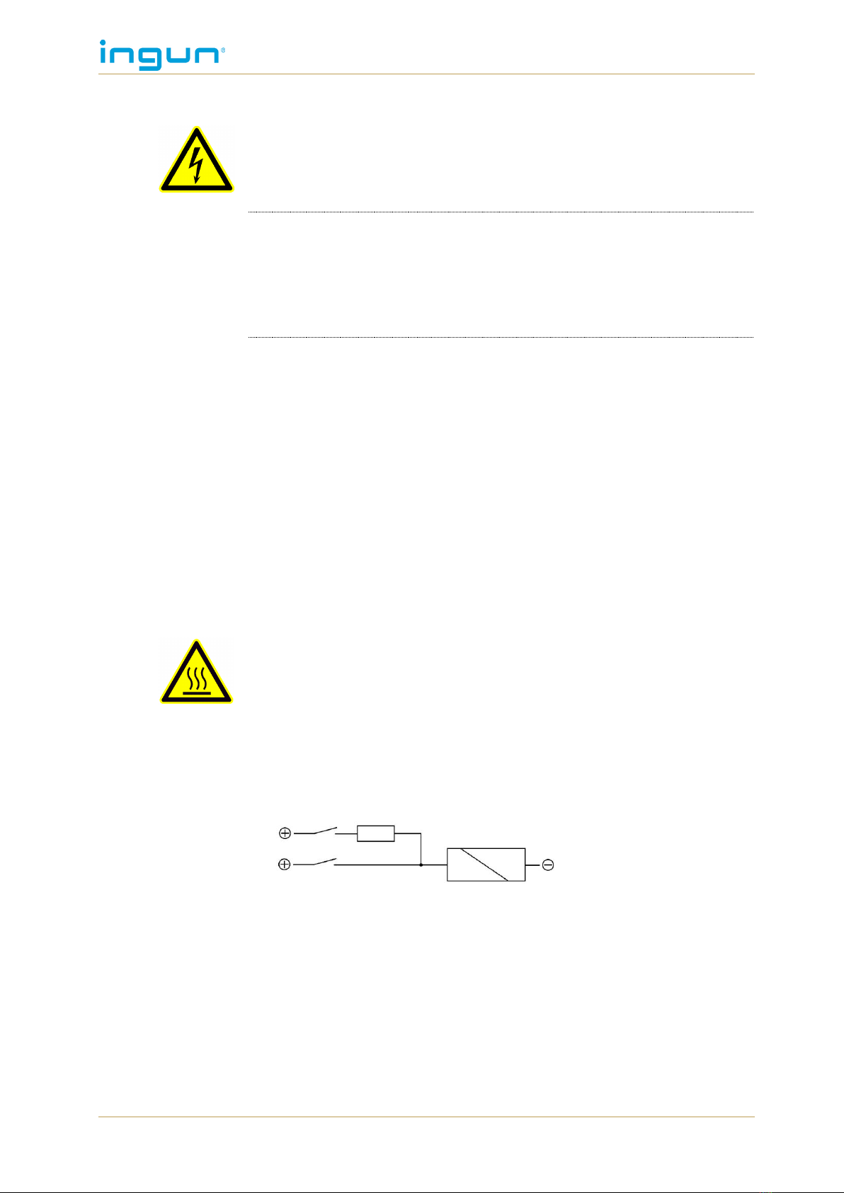
Halve the control voltage after approx. one second duty-cycle, i.e. connect
the electromagnet with two channels each and connect a resistor in the
channel for the constant current supply.
Figure 1: Activation with 2 channels
3 CUSTOMISING
The ATS is especially customised for the PCBs/UUTs to be tested. Customising normally con-
sists of spring-loaded test probes (which are installed in receptacles), the UUT/PCB centring,
the UUT/PCB support pins, the pushrods, and possibly further customising parts. Should the
UUT/PCB have side-connectors that need to be contacted, the ATS will additionally be
equipped with a connector approach mechanism (SAM).
The customising of the ATS requires care, as well as a lot of experience. High forces can occur
when there is a large number of test points. These forces can lead to deformation of the probe
Technical manual MA xxxx with ATS MAxx
©INGUN: Subject to technical changes without notice. E&OE. 8
plate and the pressure frame plate. Furthermore, asymmetrical positioning of the test probes
may require additional reinforcement of the unit.
The ATS customised by INGUN is optimally equipped for the test application in question so that
highly reliable testing is guaranteed.
3.1 Customising for stroke 22 mm (MA 3xxx)
The standard stroke is 14 mm. This ATS, which is especially customised for the MA 3xxx - 22 mm
stroke, cannot be used in the MA 2xxx. The 22 mm stroke ATS is equipped with a special insertion
blocker in order to prevent improper use (see chapter 8.3, p. 41).
3.2 Customising accessories
Within its wide range of different customising accessories, INGUN offers a great variety of match-
ing small parts and function units for the standard customising as well as for individual customis-
ing. The following overview shows only some of the different function units:
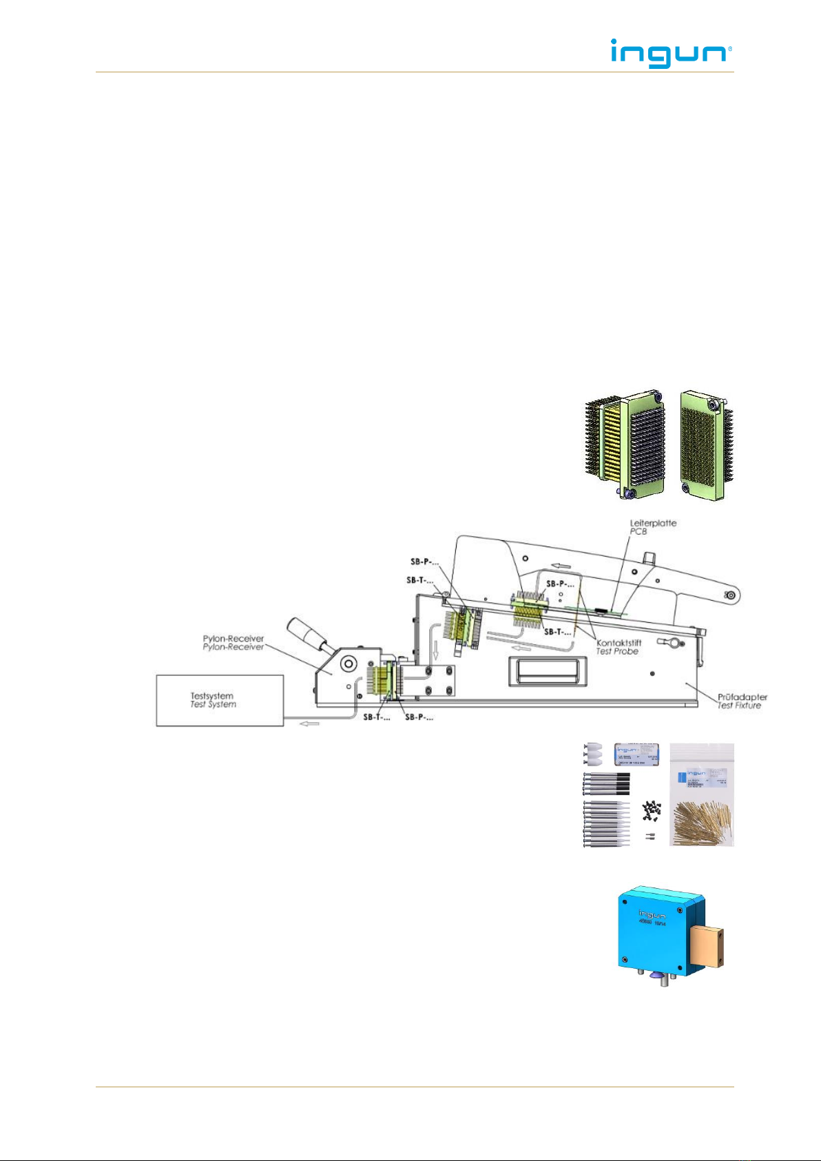
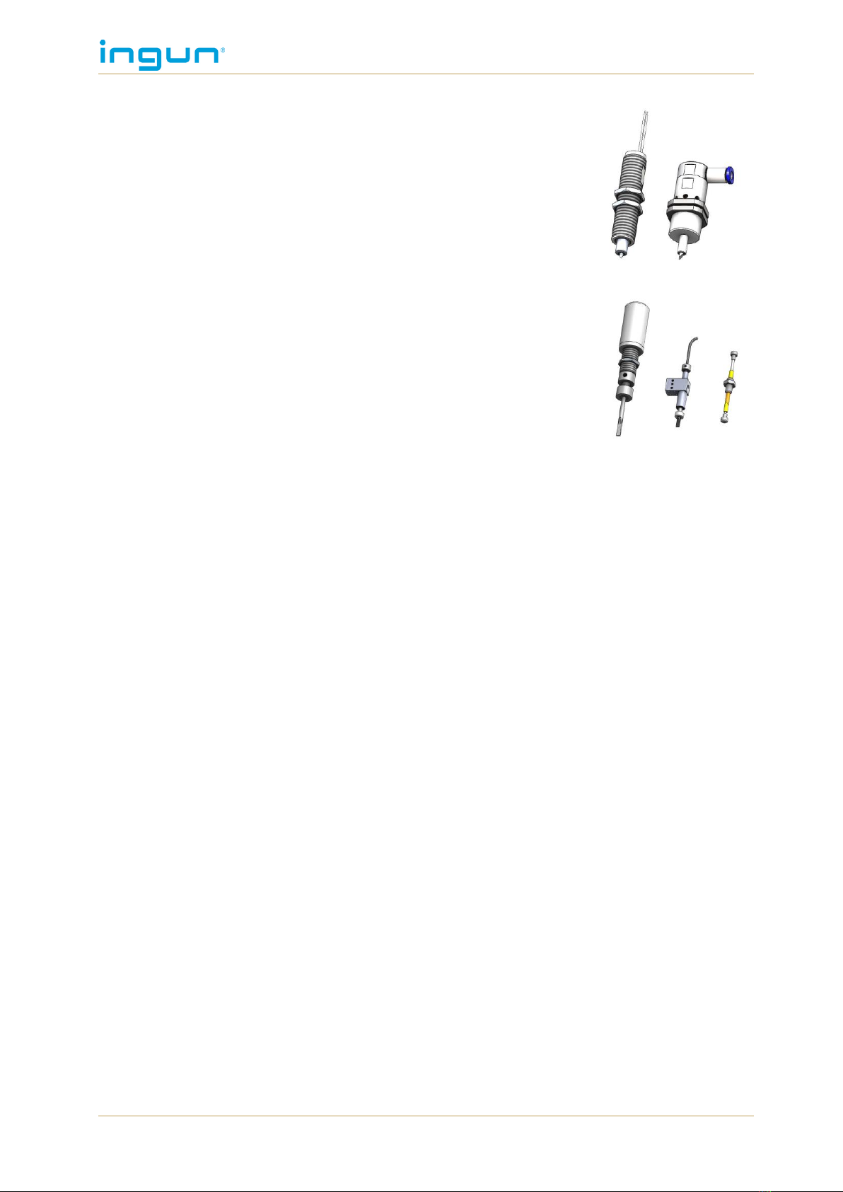
3.2.1 Interface blocks (SB)
INGUN interface blocks are used as electrically conductive connect-
ors for the reliable signal transfer in internal, external and customised
interfaces. Mounted with spring-loaded test probes, the matching con-
tact strokes guarantee consistently low contact resistance and con-
stant reliable contact quality. The working space is 15.1 ± 0.5 (see
product information “Interface blocks”).
Figure 2: Example of interface block installation
3.2.2 Start-up kit (SK)
INGUN offers different start-up kits for self-customising of the ATS.
These start-up kits include all common components necessary for
the customising –from the pre-centring to the spring-loaded test
probe (see product information “Start-up kits“).
3.2.3 Side approach mechanism (SAM)
Approach mechanisms enable the lateral approach of contacts. Man-
ual and automatic approach mechanisms are available. Using the
automatic, stroke-controlled approach mechanism, the vertical con-
tacting stroke is converted into a horizontal stroke (see product infor-
mation “Side approach mechanism“).
Technical manual MA xxxx with ATS MAxx
9 ©INGUN: Subject to technical changes without notice. E&OE.
3.2.4 Marking units (ME)
For the permanent “good”-marking, marking units with electrically or
pneumatically operated drive systems are available. The marking is
done in the form of a circular marking or circle point marking by
means of a scratching engraver, cutting engraver or milling en-
graver. The marking units are mounted in the replacement kit com-
pactly and precisely (see product information “Marking units”).
3.2.5 Potentiometer screwing unit/key button activators
Compact manual or automatic screwing units can be used for po-
tentiometer adjustments (see product information “Automatic screw-
ing unit for potentiometer adjustment “and “Manual tool for operating
buttons“).
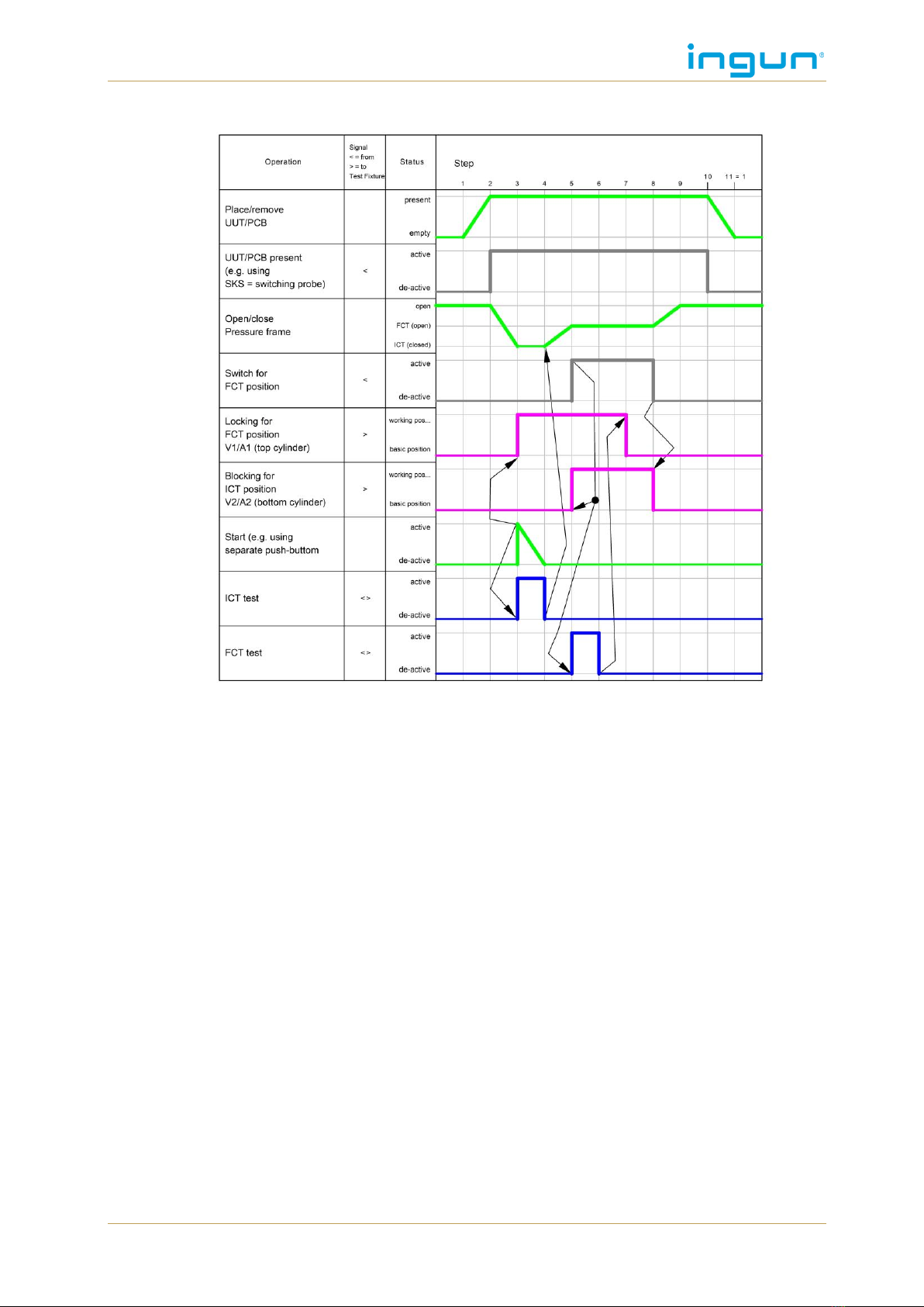
4 FUNCTIONAL SEQUENCE
The typical test sequence is displayed here using a flow-diagram. The steps carried out by the
operator are displayed in green. The UUT (Unit Under Test) detection is part of the ATS custom-
isation; it is not absolutely necessary, but highly recommended.

Technical manual MA xxxx with ATS MAxx
©INGUN: Subject to technical changes without notice. E&OE. 10
The functional sequences displayed here are the basis of INGUN product design. These can differ
depending on the test application.
5 ADDITIONAL FUNCTIONS MAXXXX
Different versions of the manual test fixtures are available with additional functions as bellow.
The “note for usage” generally must be considered because not all optional functions/additional
functions can be combined and other aspects must be considered.
5.1 Protection conductor wiring and contact protection for dangerous volt-
ages
MA 2x09
MA xx11
MA xx12
MA xx13
MA xx13T
MA xx14
40509
39851
39852
39853
39855
39854
ATS MA 09
ATS MA 11
ATS MA 12
ATS MA 13
ATS MA 11
ATS MA 14
41809
41811
41812
41813
41811
41814
When testing with a dangerous voltage (>25V AC and >60V DC) the test fixture must be
equipped with protective equipotential bonding, and protection type IP3x according to DIN EN
60529 must be fulfilled. The customising according to the low-voltage directive (NSRL) consists
of the safety protection conductor wiring (yellow/green cable) to all relevant parts and the check
via insulation resistor at pre-defined places (limit 0.3 ).
WARNING:In case of any changes of the protection conductor wiring (e.g. exchange of wires
or replacement of the cable gland), new measurement of the protection conductor
resistance is necessary!

Technical manual MA xxxx with ATS MAxx
11 ©INGUN: Subject to technical changes without notice. E&OE.
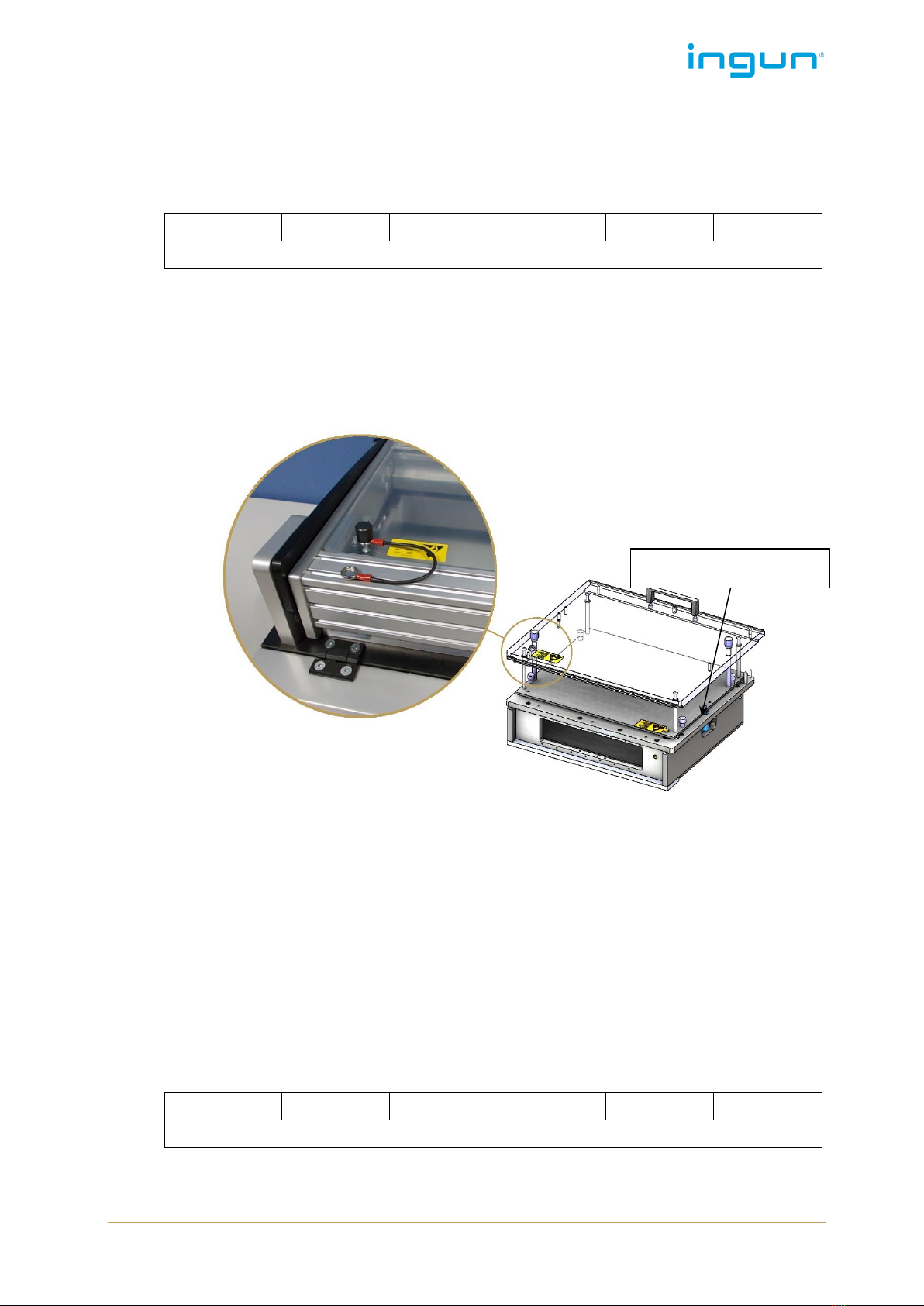
5.2 ESD assembly
MA 2x09
MA xx11
MA xx12
MA xx13
MA xx13T
MA xx14
33482
33482 (2x)
33482
ATS MA 09
ATS MA 11
ATS MA 12
ATS MA 13
ATS MA 11
ATS MA 14
See chapter 1.2.2, p. 5 for part number
In case of ESD assembly, the test fixture is equipped with an ESD wiring (black cable) with
grounding connection and a connection for an ESD antistatic strap.
Figure 3: MA2112 with ESD assembly
Note for usage
The MA 20xx with ESD customisation not equipped with an ESD coated probe plate as
standard. An ESD coated probe plated is available upon request.
The standard transport handles are not conductive. Optionally hinged metal handles are
available (see chapter 7.11, p. 33)
For ATS and test fixtures with ESD version of the first generation, new ESD discharge
cable with ESD press-stud connector can be ordered at INGUN under Part no. 48215.
The antistatic wrist strap must not be connected to the bush of the ESD discharge ca-
ble.
5.3 ESD assembly and protection conductor wiring
MA 2x09
MA xx11
MA xx12
MA xx13
MA xx13T
MA xx14
43597
43597 (2x)
43597
ATS MA 09
ATS MA 11
ATS MA 12
ATS MA 13
ATS MA 11
ATS MA 14
Part number see chapter 1.2.2, p. 5
The above mentioned part numbers shall be used only in connection to the part numbers of the
protection conductor wiring (see chapter 5.1, p. 10).
5.4 Dual-stage contacting from bottom side
The manual test fixtures are available as dual-stage basic units with electromagnetic limitation of
the contacting stages. The combined stroke is achieved manually. The first contacting stage for
ICT is achieved as soon as the pressure frame is completely closed. The second contacting stage
for FCT (that lies above the first contacting stage) is achieved by lifting the operating handle. The
limitation of both contacting stages is carried out electromagnetically by means of two stroke
magnets. To open the pressure frame, a push button switch must be activated. A standard ex-
changeable kit (ATS) with dual-stage customisation is used.
connection
ESD antistatic strap
Technical manual MA xxxx with ATS MAxx
©INGUN: Subject to technical changes without notice. E&OE. 12
The sequence of this dual-stage contacting is displayed in the following functional diagram:
Note for usage
Cannot be used with the option “locking unit for closed pressure frame” (see chapter
7.5, p. 29).
In case assembly is done with high forces (many contact probes) the option “oil break”
is necessary (see chapter 7.13, p. 35).
A “pressure frame closed” check is necessary using the dual-stage function (see chap-
ter 7.3, p. 27).
Premature opening of the fixture can cause the locking mechanism to jam.
The ICT position is only locked during FCT testing (see description).
This dual-stage function is exclusively for contacting from the bottom side. (Dual-stage
contacting from the top side is possible as a specialised solution in the exchangeable kit)
Combination with self-opener, see chapter 5.5, pg. 15

Technical manual MA xxxx with ATS MAxx
13 ©INGUN: Subject to technical changes without notice. E&OE.
5.4.1 Locked electrically
MA 2x09
MA 2x11
MA 2x12
MA 2x13
MA 2x13T
MA 2x14
60859 (left)
59508 (left)
-
59508 (left)
60856 (right)
102597 (right)
-
102597 (right)
ATS MA09
ATS MA11
ATS MA12
ATS MA13
ATS MA11
ATS MA14
48266
Figure 4: Basic unit with electromagnetic dual-stage locking unit
Specification of the components used:
Stroke magnet NC (currentless; closed) (Part number 50856) (see chapter 10.1.7, p.51)
Inductive sensor (Part number 38413) (see chapter 10.1.5, p. 50)
The electromagnetic in currentless locking unit used here must be actively switched to the
“open” setting.
CAUTION:BURNING ON HOT SURFACES!
Hot coil housing on electromagnets
Use INGUN magnet control when electromagnets are switched on for ex-
tended periods of time.
Sensor for
FCT position
electromagnet for
FCT position
electromagnet for
blocking the
ICT position
Technical manual MA xxxx with ATS MAxx
©INGUN: Subject to technical changes without notice. E&OE. 14
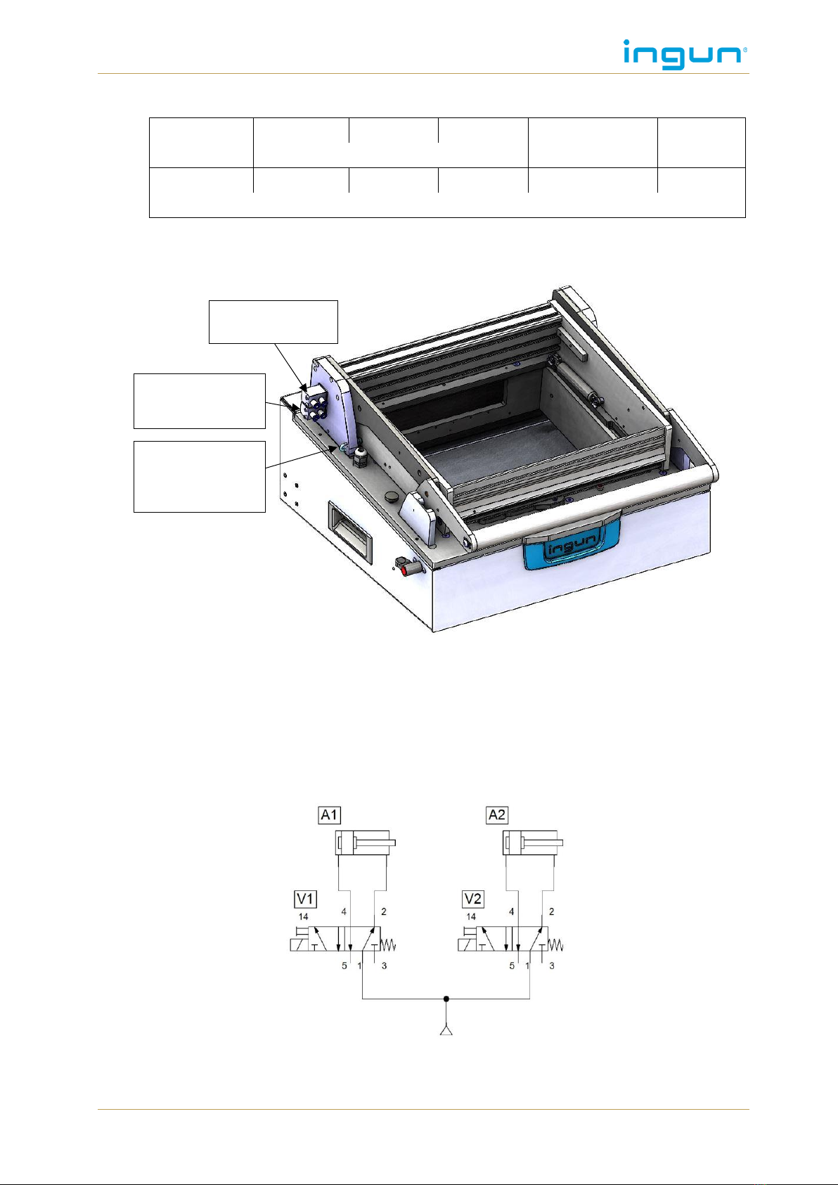
5.4.2 Pneumatic locking
MA 2x09
MA 2x11
MA 2x12
MA 2x13
MA 2x13T
MA 2x14
59555
59507
59507/100700 *)
59507
ATS MA09
ATS MA11
ATS MA12
ATS MA13
ATS MA11
ATS MA14
48266
*) Part 59507 is mounted on the left side of the left drive unit and part 100700 is mounted on the
right side of the right drive unit.
Figure 5: Basic unit with pneumatic dual-stage locking
Specification of the components used:
Inductive sensor (Part number 38413) (see chapter 10.1.5, p. 50)
Pneumatic cylinder 12-10 (Part number 49273)(see chapter 10.1.11, p. 52
Specification of optional components (not included in delivery):
Valve assembly 5/2-way (Part number 42702) (see chapter 10.1.10, p. 51)
Compressed air combination (Part number 14241) (see 10.1.17, p. 53)
Pneumatic plan
pneumatic cylinder
for FCT position
sensor for
second contacting
stage (FKT posi-
tion)
pneumatic cylinder
for blocking the ICT
position
Technical manual MA xxxx with ATS MAxx
15 ©INGUN: Subject to technical changes without notice. E&OE.
5.4.3 Mechanical stroke limitation
MA 2x09
MA 2x11
MA 2x12
MA 2x13
MA 2x13T
MA 2x14
50914
50912
50913
50912 (2x)
50913
ATS MA09
ATS MA11
ATS MA12
ATS MA13
ATS MA11
ATS MA14
48266
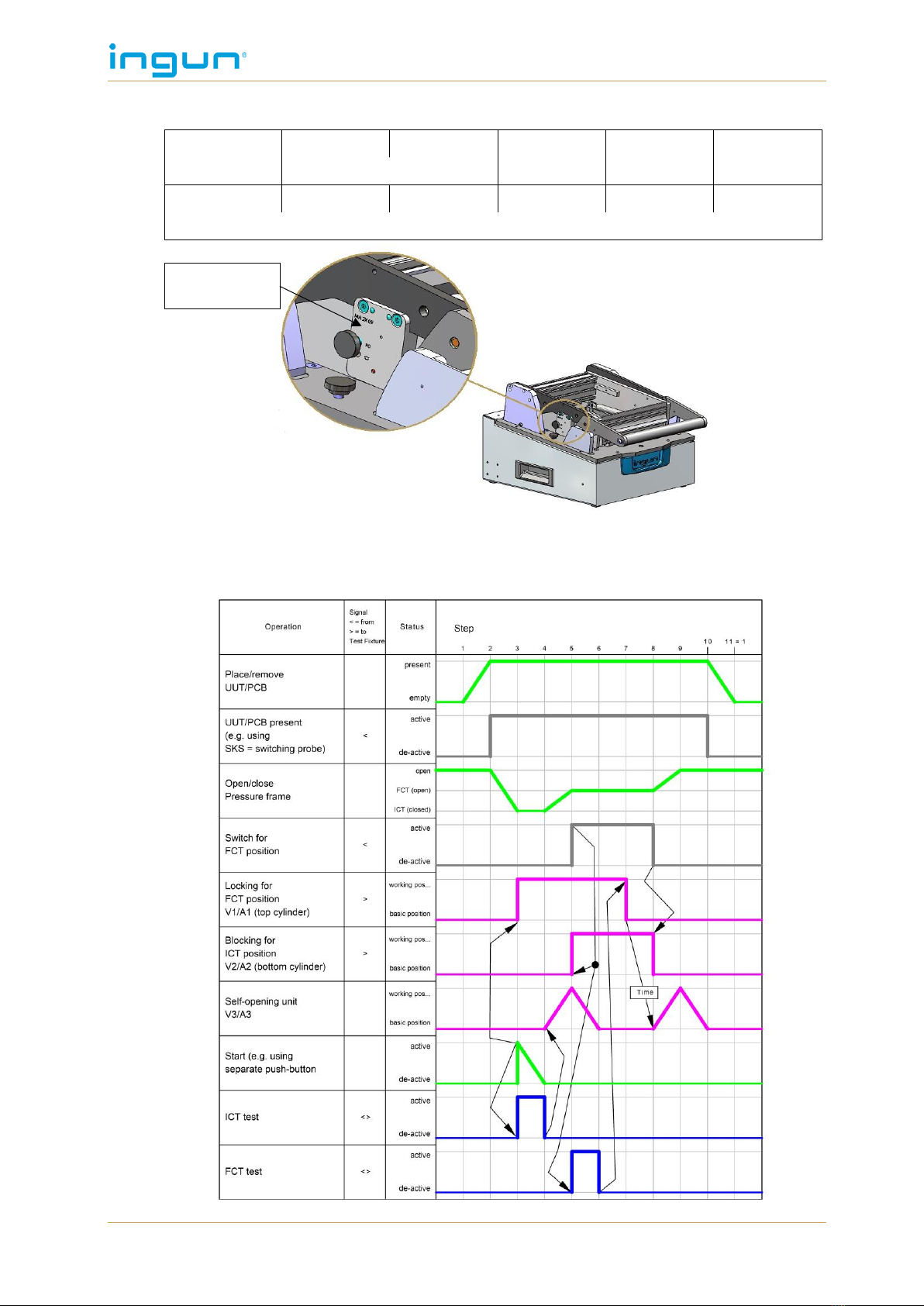
5.5 Dual-stage contacting with self-opener
The dual-stage contacting process with self-opener is shown in the following function diagram:
dual-stage
mechanism

Technical manual MA xxxx with ATS MAxx
©INGUN: Subject to technical changes without notice. E&OE. 16
5.5.1 Electrical dual-stage contacting with self-opener
MA 2x09
MA 2x11
MA 2x12
MA 2x13
MA 2x13T
MA 2x14
-
45220
45220
45220 (2x)
45220
-
59508
59508
59508/100696 *)
59508
-
59558
59559
59558 (2x)
59559
*) Part 59508 is mounted on the left side of the left drive unit and part 100696 is mounted on the
right side of the right drive unit.
5.5.2 Pneumatic dual-stage contacting with self-opener
MA 2x09
MA 2x11
MA 2x12
MA 2x13
MA 2x13T
MA 2x14
42701
42700
42700
42700 (2x)
42700
59555
59507
59507
59507/100700
59507
51434
59558
59559
59558 (2x)
59559
59507
42700
59558
59508
45220
59558

Technical manual MA xxxx with ATS MAxx
17 ©INGUN: Subject to technical changes without notice. E&OE.
Specification of the components used:
Inductive sensor (Part number 38413) (see chapter 10.1.5, p. 50)
Pneumatic cylinder 12-10 (Part number 49273)(see chapter 10.1.11, p. 52
Specification of optional components (not included in delivery):
Valve assembly 5/2-way (Part number 42702) (see chapter 10.1.10, p. 51)
Compressed air combination (Part number 14241) (see 10.1.17, p. 53)
Pneumatic plan
5.5.3 Mechanical dual-stage contacting with pneumatic self-opener
MA 2x09
MA 2x11
MA 2x12
MA 2x13
MA 2x13T
MA 2x14
42701
-
-
-
-
103550
-
-
-
-
51434
-
-
-
-
Technical manual MA xxxx with ATS MAxx
©INGUN: Subject to technical changes without notice. E&OE. 18
6 ADDITIONAL FUNCTIONS ATS MAXX
The exchangeable kits are available with the following additional functions:
6.1 ESD version
ATS MA 09
ATS MA 11
ATS MA 12
ATS MA 13
ATS MA 11
ATS MA 14
See chapter 1.2.2, p. 5 for part number
An ESD version is available for electrostatic sensitive components. This affects the manual fixture
and requires a specialised exchangeable kit. In this case, all components in the basic unit are
electrically attached to the ground connection on the back panel of the basic unit. Grounding is
done by the customer using a connection cable with 1.5 mm² cross section. Grounding of the
bottom part takes place automatically via a spring-loaded discharge probe, assembled in the basic
unit. Grounding of the top part of the exchangeable kit takes place via a grounding cable installed
at the basic unit which must be plugged to the pressure frame plate.
Part number see chapter 1.2.2, p. 5
Figure 6: ATS as ESD version with pressure frame unit wiring
Note for usage
ESD function of ATS is only achieved in connection with the additional function of the
ESD assembly in the test fixture (Part no. 33482 ESD assembly / Part no. 43597 ESD
customising with protection conductor wiring).
ESD function is only achieved with respective ESD components such as ESD pushrods
and ESD pre-centring.
The ESD layer around the GKS has to be removed.
For ATS and test fixtures with ESD version of the first generation, new ESD discharge
cable with ESD press-stud connector can be ordered at INGUN under Part no. 48588.
(For more information see product information “Premium ESD-customising”)
6.2 Radio frequency version
ATS MA 09
ATS MA 11
ATS MA 12
ATS MA 13
ATS MA 11
ATS MA 14
See chapter.1.2.3, p. 5 for part numbers
The radio frequency exchangeable kits are used to contact highly sensitive RF boards precisely
and reliably, and to measure the radio frequency signals in a fail-safe way (see product infor-
mation “MA radio frequency exchangeable kits“).
ESD interface contact

Technical manual MA xxxx with ATS MAxx
19 ©INGUN: Subject to technical changes without notice. E&OE.
See chapter.1.2.3, p. 5 for part numbers
Figure 7: ATS MA12/HF backside
without internal interface
Figure 8: ATS MA12/S-7/HF backside
with internal interface
Spare parts and parts subject to wear can be found under chapter 9.3.3, page 48.
This manual suits for next models
5
Table of contents
Other Ingun Test Equipment manuals


