Retrotec DucTester DU200 User manual

QG130 Page 1 of 8
Made in Everson, WA USA
rev-2014-08-05
QuickGuide
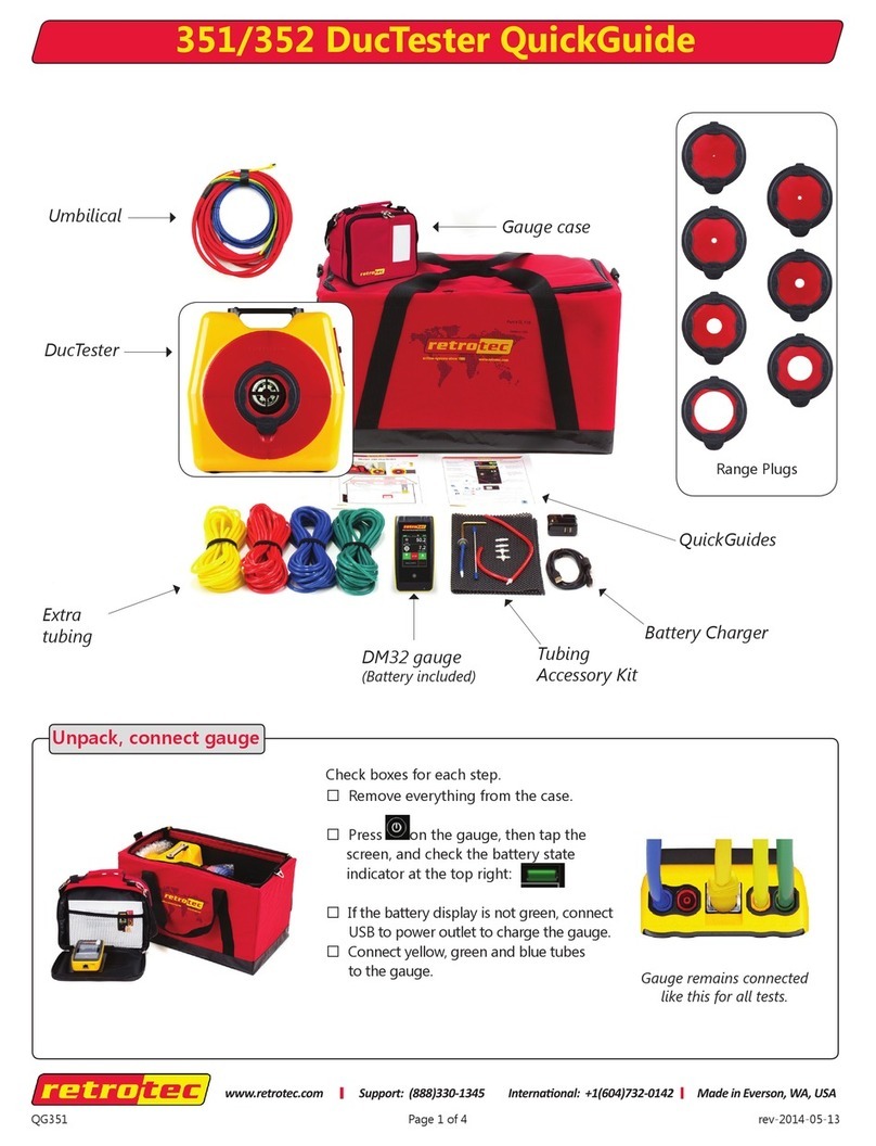
DU200 DucTester
Flex Duct
DM-2 gauge
(Batteries included)
Umbilical
Flange
Low-Range Ring
Mid-Range Ring
DucTester
Grill Mask
QuickGuides
Battery Charger
Tubing
Accessory Kit
Unpack, connect DM-2 gauge
Check boxes for each step.
□Remove everything from the case.
□Install 4 NiMH AA batteries.*
□Plug in the battery charger.
□Press [On], then [Exit], to display
the battery indicator.
□Charge for 18 hrs.
□Connect yellow, green and blue tube
to gauge.
□Slide gauge into the clear sleeve and
velcro Umbilical to case.
Gauge remains connected
like this for all tests.
*If changing to non-rechargeable batteries, disable
charging in [Setup] menu. For steps see:
Quick Guide DM-2 mark II Digital Gauge, page 1
www.retrotec.com Sales & Support: (855)738-7683 Internaonal: (604)732-0142

Step 1: Prepare ducts and house
□Seal all supply and return grills/registers, including
any exterior air inlets, with Grill Mask or tape.
□Open all interior doors leading to rooms containing
a supply or return register, and open an exterior door
or window.
□Shut off all HVAC (exhaust fans, dryers, A/C, furnaces).
Page 2 of 8
Step 2: Connect to ducts
□Turn off air-handler
and remove all lters.
□Tape Flange to main
return or air handler
cabinet using
masking tape.
□Attach Flex Duct to
Flange.
□Install Mid-Range Ring to start,
as most systems can be tested
on this Range Conguration.
□Press [Range Cong] to select
range on gauge to match fan,
whenever Range Ring is changed.
□Press [Auto Zero] until “On” appears -
to keep the gauge
zeroed and ready
to measure.
□Press [Time Avg] until “4s” appears.
□Press [Device] until “Retrotec DU200”
appears.
If desired Device does not appear, see:
QuickGuide DM-2 mark II Digital Gauge,
Add/Remove Devices section
□Press [Range Cong] until
“Mid” appears.
□Press [Mode] to cycle through results.
Select based on “Get the results you
need” on page 4.
If you can’t nd the required results, see:
QuickGuide DM-2 mark II Digital Gauge
Prepare the DM-2 gauge
Next, prepare the ducts, house, and fan following
Steps 1 through 3.
Mid
Low
Open
Remove Range Rings for
leakier ducts, add Rings
for tighter ducts.

□ Press [On] twice to get to main
screen.
□ Adjust fan speed knob clockwise
until “PrA” reaches test pressure.
□ If not possible, go to Step
5 for advice on changing setup.
□ Connect Speed Control Cable to
fan.
□ For a test pressure of 25 Pa *, press
[Set Pressure] [25] [Enter].
* 50 Pa for Northwest ENERGY STAR.
□ Press [@ Pressure] to display what
the result would be at exactly 25 Pa.
Page 3 of 8
Step 3: Connect DM-2 gauge & fan
□Insert blue tube into the
supply register closest to
the air handler.
□ Read results directly from the gauge.
Speed Control Cable
□Connect power cord.
□Switch to on: “ l “. Green
light indicates that power
is connected.
□Connect yellow and green
tubes to matching color
ports on fan. Ethernet
style Speed Control Cable
will disable the knob. It is
connected later in Step 4.
If Pressurizing, see tubing setup on page 7.
□Connect Flex Duct to fan inlet for depressurization. Ready to conduct the test by depressurizing the ducts:
Depressurization is easiest and permitted in all States
except CA & WA where it can still be used to
evaluate, but not for a final result.
Step 2: Connect to ducts cont’d Total Duct Leakage Test: Depressurize
Step 4: Conduct test
To pressurize, connect the Flex Duct to fan exhaust.
All other connections remain the same
pressurize
Inlet
airow
Exhaust
Inlet
with Range Rings
inside Flex Duct
Exhaust
depressurize
Solid green Status light
indicates DM-2 is ready
to control speed.
airow
Depressurizing works best because the fan pulls the
Grill Mask tight on the registers during the test.

Flow at the induced pressure is the
simplest result.
Mode = “Flow”
Units = “CFM”
Flow per ft2 (sq ft) is required in some
states, such as WA.
Mode = “Flow/Area”
Units = “CFM/ft2”
(enter a value for Area)
Flow per 100 ft2 is required for the
following states:
Mode = “Flow/Area”
Units = “CFM/100 ft2”
(enter a value for Area)
Flow reads “TOO LOW” or “----” at test pressure?
If the test pressure has been reached, but
“TOO LOW” or “----” appears, the fan is running too
slowly to measure ow.
□Add the next Low-Range Ring.
□Change [Range Cong] on the DM-2 to match.
□Re-adjust speed.
Cannot achieve test pressure at full speed?
If fan reaches 100% speed before reaching the target
pressure:
□ Remove a Range Ring and try again.
□Change [Range Cong] on the DM-2 to match.
□Check seals on all registers. Look for disconnected
ducts or ducts open to outdoors.
□Press [@ Pressure] to get the gauge to calculate
what the ow would be at exactly 25 Pa.
Page 4 of 8
Get the results you need
□ Press [Mode] until required results appear
Show results as leakage area
Equivalent Leakage Area (EqLA) describes the leakage
area in terms of one large hole in a at surface.
□ Press [Mode] until “EqLA” appears.
“PrA” displays the duct pressure and “EqLA” shows
the combined size of all the holes in the ducts.
Step 5: Desired results not achieved?
620 CFM is the ow rate that would occur at 25 Pa,
even though only 22 Pa was achieved.
CT
DC
DE
GA
ID
IL
IA
ME
MD
MA
NH
NJ
NY
NC
PA
RI
TX
VT
Use “Jog” to activate arrow keys
[▲] [▼]
then adjust target speed or pressure.
Use “Hold” to freeze results display
and hold fan speed.
□ Press [Jog/Hold] until “Hold” appears in top center
of display.
□ Press [Jog/Hold] again to cancel “Hold”.
□Press [Jog/Hold] until “Jog” appears.
□The [▲] [▼]keys now adjust the speed just like a
TV remote. With [Set Speed] the % speed
changes. With [Set Pressure] the pressure changes.
Hold display and Jog speed
Leakage area is not a required result, but is a nice
way to visualize the size of the hole in the ducts.
□ Press [Enter] numbers [Enter] to
input the oor area if CFM/ft2or
CFM/100 ft2is used.
*Floor area of 2000 square feet
was entered in the above examples.
[Enter] [2000] [Enter]
“Jog” is only available when [Set Pressure] or
[Set Speed] have a value entered.
The display will be frozen with the current values.
□ Press [Setup] for menu to change result units
□ Press [▼] to nd “Mode Setup”, then [Enter]
□ Press [▼]until the Mode you want is highlighted
□ Press [Enter] to change displayed result units
□ Press [Exit] twice to return to main menu

Page 5 of 8
Free Training Videos
We’re here to help!
Check out Retrotec’s
YouTube page, with all the
videos you’ll need to help
you setup, run, or trouble-
shoot your equipment!
● Sign up for our monthly gauge setup webinars.
● Bookmark our blog! Everything from new testing techniques to industry updates.
● Our tech support is always ready to eld phone-in troubleshoot and testing
questions. Give us a call!
● Access all Retrotec training videos here: youtube.com/RetrotecTraining
Duct Testing
Watch universal training
videos including:
●Set up
● Procedures
● Troubleshooting
Leakage: Blower Door
Watch video demonstrations
including:
● Blower Door set up
● Common leak locations
● Software
● House preparation
Pressure: Gauge Training
Get help to successfully set
up and use digital pressure
gauges.
● Gauge set up
● Discover modes & devices
● Perform calibration checks
retrotec.com/residential/SupportCenter/SetupWebinars.aspx
retrotec.com/blog.aspx
1-855-738-7683
Retrotec’s playlist includes:

Page 6 of 8
To measure the air leakage from the
duct system to outdoors requires both a
DucTester and a Blower Door system.
The Blower Door depressurizes the house
and the DucTester depressurizes the
ducts so leakage from the duct system
back into the conditioned space of the
home is neutralized.
Method #1:
Method #2:
□Connect the red T-connected tubes to red ports
per diagram.
□Press [Set Pressure] [25] [Enter] on DucTester
gauge then on Blower Door gauge.
□Press [@ Pressure] on DucTester gauge to display
the results “@25Pa”.
□When “25 Pa” +/– 1 is achieved on both gauges,
record duct leakage to outdoors from the DucTester
gauge.
□Connect tubes to gauges per diagram.
□With DucTester off, set the Blower Door gauge
to -25 Pa by pressing
[Set Pressure] [25] [Enter].
□Press [@ Pressure] on DucTester to remove
“@25Pa” from the display.
□Set the DucTester to “0 Pa” by pressing
[Set Pressure] [0] [Enter]. When “0 Pa” +/– 1
is achieved, record duct leakage to outdoors
from the DucTester gauge.
Method 1 uses the DucTester set up the
same way as for the Total Duct Leakage
test, and allows use of [@ Pressure] to
increase accuracy.
Results are easier to visualize since both
the duct and house pressure can be seen.
Method 2 does not require connecting
a red tube to the DucTester gauge but
results in large errors if [@ Pressure] is
turned on.
Set DucTester gauge to 0 Pa,
Blower Door gauge to -25 Pa **
Set both gauges to -25 Pa **
Blower Door gauge DucTester gauge
Optional Test
Duct Leakage to Outdoors: Depressurize
Options
** If 50 Pa test pressure required, use 50 in all instructions.
Method# 1

□ Connect Flex Duct to fan exhaust.
□ Check that tubing is connected the same as for
depressurize test (step 3).
□ Conduct test (step 4).
Duct Leakage to Outdoors:
Pressurize
Follow depressurize test method (page 6) except both
fan directions are reversed.
Page 7 of 8
Total Duct Leakage: Pressurize
Optional Test
Pressurizing can blow the Grill Mask off the registers!
Options
pressurize
Inlet
airow
Exhaust
□Pass the Flange through the 10 inch hole in the
Flow Hood and tape it inside.
□Attach the Flex Duct.
□ Secure the Flow Hood over the register
To measure Duct leakage:
□ Connect the Flex Duct to the fan and test as usual.
To measure HVAC System Flow:
□ For measuring supply ows, attach the Flex Duct
to the inlet (suction) side of the fan.
□ For measuring return ows, attach the Flex Duct
to the exhaust (discharge) side of the fan.
□ Connect the umbilical to the DucTester.
□ Attach the blue tube to the Flow Hood and gauge.
□ Press [@ Pressure] until “@” is removed from
display
□ Press [Mode] to select “Flow”
When a denite pressure appears on “PrA”:
□ Adjust the speed until “PrA” reads a pressure of 0 Pa.
Or
□ Press [Set Pressure] [0] to have the DucTester
automatically achieve a 0 pressure.
□ Read the HVAC system ow result directly from
the gauge
Using the optional Flow Hood
Connect it quickly to ceiling level returns to measure
duct leakage or use it with your DucTester as a Pow-
ered Flow Hood to accurately measure HVAC system
ow rates.
Flow Hood blue tube

Tubing Accessory Kit
35 ft (10 m) of blue, red, yellow and green 1/4 inch
(12mm) outside diameter tubing. Static Pressure
Probe, 4 inch (100 mm) x 1/8 inch (6 mm) outside
diameter metal probe, 2 T and 2 male-to-male con-
nectors. Red L for duct leakage to outdoors test.
Part #: TU119
Flow Hood
24 x 24 inches
(61 x 61 cm)
Part #: PP105
Page 8 of 8
Optional accessories
12.5ft (3.8m)
Flex Duct for
DucTester
Part #: DU161
Flange
to connect
Flex Duct to
register
Part #: DU157
Verication
Plate
Part #: DU159
Deluxe Cordura Toolbag with
Shoulder Strap
Part #: TL118
Grill Mask 12in x 216ft,
12in perfs,
Hi-stick White,
Single Roll
Part #: GR116
Part #: GR117 (for case of 3)
Umbilical for
DucTester
fans, 7ft (2 m)
Part #: DM240
Optional DU159 Verication
Plate shown.
□Tape the optional ow
Verication Plate to the
Flange and attach the
red tube.
□Attach the Flex Duct to the
exhaust side of the fan
to pressurize the Flex Duct.
□Stretch the Flex Duct to
it’s full length.
□Set the DM-2 to measure
“Flow” in “CFM @25 Pa”.
□Adjust the speed until
“PrA” reads close to 25 Pa.
□Read the Verication
Plate to determine the
acceptable range for ow.
Typically, 100 to 110 CFM
is a pass.
Check gauge operation and check for blocked, leaking or
pinched tubes weekly, and anytime results are in question.
To perform the gauge check, you will need the gauge
and Umbilical.
□Press [Exit] [Time Average] until “4s” appears.
□Press [Mode] repeatedly to display “PrB”.
□Connect the yellow tube between the red and
yellow ports.
□Repeat between different ports with each of the
tubes you use for testing.
Field check gauge weekly
If readings on “PrA” and “PrB” are within 2% and
don’t drop rapidly, the tube is not blocked or
leaking and the gauge is correct.
Checking your gauge
and tubes regularly will
eliminate a common
source of error in
readings.
Mid-Range Ring
& Low-Range
Ring
(Mid) Part #: DU154
(Low) Part #: DU155
Check the DucTester system monthly with a
known setup―if flow is outside the acceptable
range then system needs full calibration.
Field check system monthly
Table of contents
Other Retrotec Test Equipment manuals