InHand EC900 Series User manual

Edge Computer EC900 Series
User Manual
(Applicable for Debian10,IEOS V2.0.0 and above)
Version2.0, October 2023
www.inhandnetworks.com
The software described in this manual is provided according to the license
agreement and can only be used according to the terms of the agreement.
Copyright Notice
©2023 InHand Networks.All rights reserved.
Trademarks
The InHand logo is a registered trademark of InHand Networks.
All other trademarks or registered trademarks in this manual belong to
their respective manufacturers.

Disclaimer
InHand Networks reserves the right to change this manual, and the product
is subject to subsequent changes without prior notice. We will not be
responsible for any direct, indirect, intentional, or unintentional damages
and hidden dangers caused by improper installation and use.

Contents
1 Introduction............................................................................................................................................................. 5
2 Hardware installation instructions.................................................................................................................... 5
2.1 Introduction..................................................................................................................................................... 5
2.2 EC942 panel .................................................................................................................................................... 5
2.3 EC942 external connector........................................................................................................................... 6
2.3.1 Ethernet .................................................................................................................................................... 6
2.3.2 Serial port................................................................................................................................................. 7
2.3.3 CAN............................................................................................................................................................ 8
2.3.4 Switching Input interface (Digital Input) ........................................................................................ 8
2.3.5 Switching Output interface (Digital Output)................................................................................. 8
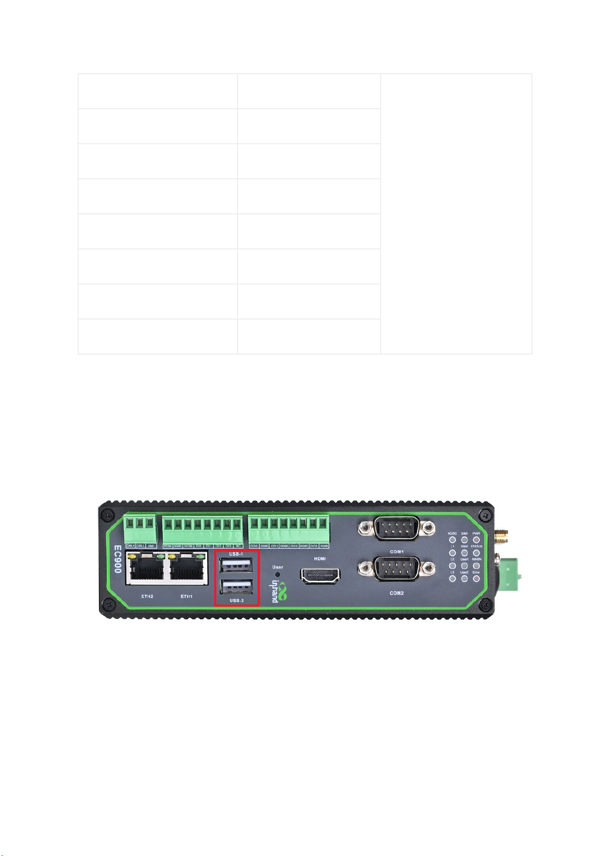
2.3.6 USB............................................................................................................................................................. 9
2.3.7 LED ...........................................................................................................................................................10
2.3.8 User programmable keys..................................................................................................................13
2.3.9 DC input .................................................................................................................................................13
2.3.10 SIM card slot.......................................................................................................................................13
2.3.11 MicroSD card slot..............................................................................................................................14
2.3.12 Restore factory keys .........................................................................................................................14
2.3.13 Switch the machine button............................................................................................................15
2.3.14 Antenna interface..............................................................................................................................15
2.3.15 Dial switch............................................................................................................................................17
2.3.15 mSATA hard disk interface.............................................................................................................17
3 Getting Started.....................................................................................................................................................18
3.1 Connect to the EC900................................................................................................................................18
3.1.1 Connecting via the SSH Console....................................................................................................19
3.2 User Account management .....................................................................................................................21
3.2.1 Switch to the root user ......................................................................................................................21
3.2.2 Creating and deleting user accounts............................................................................................22
3.2.3 Disable the default user account....................................................................................................22

3.3 Network administration and system administration........................................................................23
3.3.1 web Management based on IEOS .................................................................................................23
3.3.2 Linux-based command-line management.................................................................................39
4 Advanced configuration of peripheral interfaces .....................................................................................45
4.1 Serial Port.......................................................................................................................................................45
4.1.1 Change the serial port Settings ......................................................................................................46
4.1.2 View serial port information: ...........................................................................................................48
4.1.3 Set the baud rate of COM1 serial port:........................................................................................48
4.1.4 Set the baud rate of COM2 serial port.........................................................................................49
4.2 the USB interface.........................................................................................................................................49
4.2.1 USB auto-mount .................................................................................................................................49
4.2.2 micro SD card mounts automatically............................................................................................50
4.2.3 mSATA hard disk mounts automatically......................................................................................50
4.3 CAN bus interface .......................................................................................................................................52
4.3.1 Configure the connection CAN interface ....................................................................................53
4.4 IO Debugging...............................................................................................................................................53
4.5 GPS...................................................................................................................................................................54
4.6 Toggle the machine button .....................................................................................................................55
4.6.1 Turn off the device..............................................................................................................................55
4.6.2 Boot the device ....................................................................................................................................55
5 Safety.......................................................................................................................................................................55
5.1 sudo mechanism.....................................................................................................................................55
5.2 Firewalls......................................................................................................................................................56
5.3 TPM2.0........................................................................................................................................................56
6 The system restores factory Settings and updates...................................................................................57
6.1 Restore factory Settings........................................................................................................................57
6.2 System Upgrades....................................................................................................................................58
7 Programming Guidelines ..................................................................................................................................58
A guide to IO Programming...........................................................................................................................63
7.2 Led Programming Guide ..........................................................................................................................64
7.3 Cross-compilation.......................................................................................................................................66
1 Introduction
This user's manual is for the EC900 series of edge computers based on the
Arm architecture and covers a complete set of instructions for all
supported models. Before referring to these sections, verify that the
hardware specifications of your computer model support the
features/Settings covered.
2 Hardware installation instructions
In this chapter, we will cover the hardware installation instructions for
the EC900 series of edge computers based on the Arm architecture.
2.1 Introduction
The following sections describe the application of external connectors and
pin distribution of the EC942 series, using the EC942 series as an example.
2.2 EC942 panel
Top surface panel
Front panel
2.3 EC942 external connector
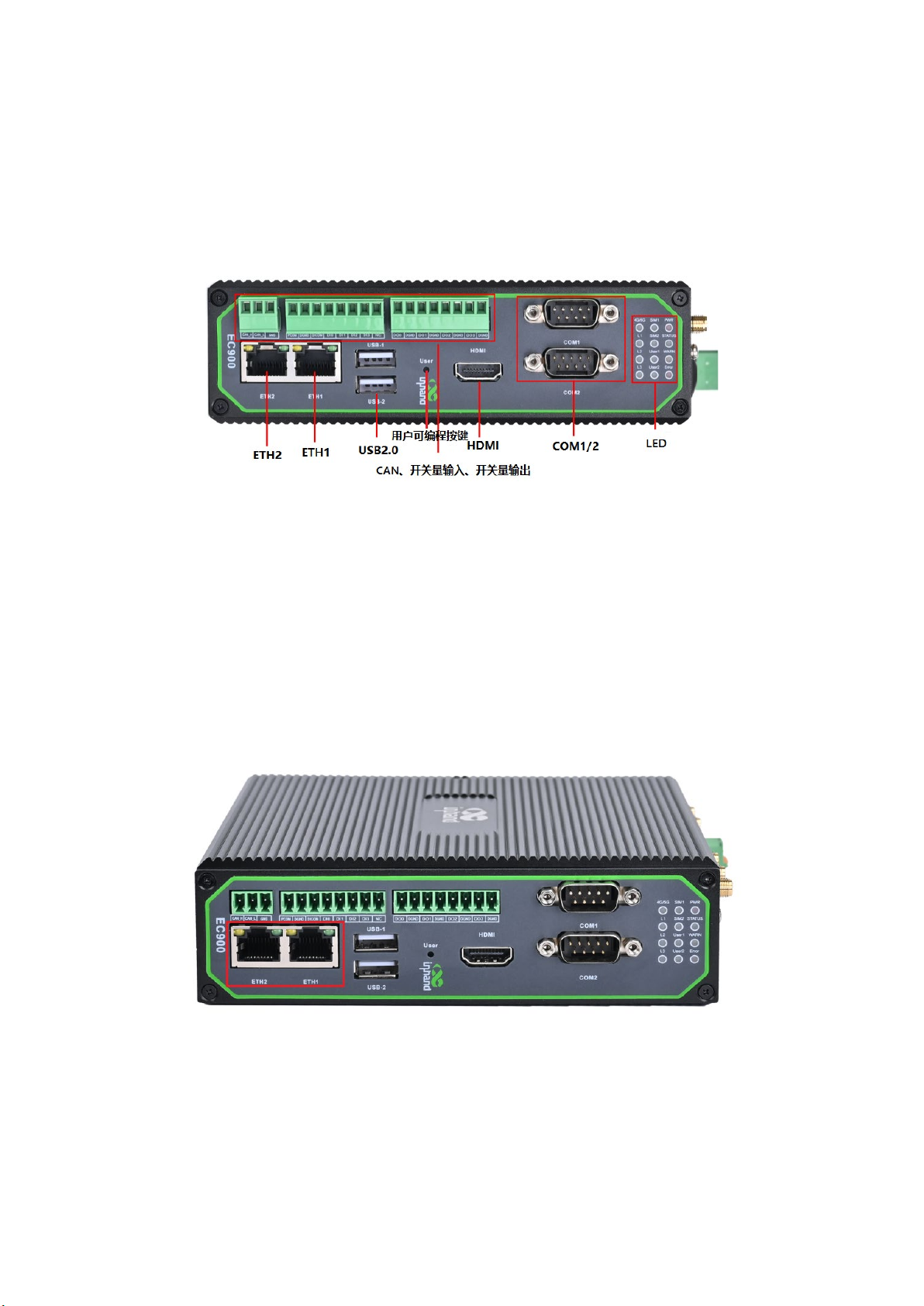
2.3.1 Ethernet
This is a dual RJ45 connector for Ethernet connection
The EC942 has 2 RJ45 Ethernet ports and supports 10M/100M/1000M adaptive rates.
Green light: LINK indicator, 1000M interface is on for the end device, and 10/100M
interface is off for the end device.

Yellow light: ACT light, flashing when there is data
2.3.2 Serial port
EC942 supports two-channel serial port, support RS-232 or RS-485 or RS-422
communication, software can be configured.
DB9 pin
number
Pin name
Pin Definition
1
2
RS-232 RxD/RS-422 TxD+ RS-232 receive /RS-422 send positive
3
RS-232 TxD/RS-485 B/RS-422
RxD-
RS-232 send /RS-485 signal B/RS-422
receive negative
4
5
GND RS-232 ground
6
7
RS-485 A/RxD+ RS-485 signal A/RS-422 receive positive
8
RS-422 TxD- RS-422 send negative
9

2.3.3 CAN
EC942 has 1-way CAN bus interface and supports CAN 2.0A/B standard. It is
compatible with CAN FD and can achieve a maximum rate of 5Mbps.
Signage
Features
CAN_H CAN high level data line
CAN_L CAN low level data line
GND to
2.3.4 Switching Input interface (Digital Input)
Interface identification
Features
Description
PCOM
Power common terminal
4
-way digital input DI,
Dry contact state
"1" : Closed dry contact state
"0" : disconnected
Wet contact state "1" :+10~+30V/
-
30 ~
-10VDC
Wet contact state "0" : 0 ~ +3V/
-
3 ~ 0V
Isolate 3000VDC
DGND
Power reference ground
DICOM Input public side
DI0 Digital input port 0
DI1 Digital input port number 1
DI2 Digital input port number 2
DI3 Digital input port number 3
NC There is no
2.3.5 Switching Output interface (Digital Output)
Interface identification
Features
Description
DO0 Digital output port 0
4 digital output DO,
Isolated 3000VDC
DGND Ground end
DO1 Digital output port number 1
DGND Ground end
DO2 Digital output port 2
DGND Ground end
DO3 Digital output port No. 3
DGND Ground end
2.3.6 USB
The EC942 provides two USB 2.0 Host ports.

2.3.7 LED
EC942 has 12 LED lights to indicate the power supply and system operation
status respectively.
Signage
Name
Definition
PWR
Power indicator
Power on and always on
STATUS
System operating status
indicator light
When the system starts normally,
the STATUS blinks. If the system
fails to start due to an
exception in the system startup
phase; Or when the factory
recovery
operation has not been
completed, STATUS is long out.
WARN
Warning indicator light
The WARN light flashes when
there is a warning exception in
the system and the system

upgrade or factory restoration
has not been completed.
Error
Error indicator light
Wh
en a serious system Error
occurs and the system upgrade or
factory restoration has not been
completed, the Error light
blinks.
SIM1
SIM1 card indicator,
Select SIM card 1 for dialing,
select SIM card 2 for dialing or
turn off dialing, long off.
SIM2
SIM1 card indicator light,
always on if selected
When SIM card 2 is selected for
dialing, it is always on. When
SIM card 1 is selected for
dialing or dialing off, it will
be long off.
User1
User Programmable indicator 1
It is off by default and can be
con
trolled by user programming
User2
User Programmable indicator
light 2
It is off by default and can be
controlled by user programming
4G/5G
Cellular connection status
indicator
Keep on after successful dialing
L1
Cellular signal strength
See
Cellular Signal Strength
Indicator instructions
L2
Cellular signal strength
L3
Cellular signal strength

Cellular signal strength indicator
LED
No signal
Weak signal (RSSI <
-
90)
Moderate signal (
-
90
<= RSSI <
-70)
Strong signal
(RSSI >=
-70)
L1
destroy
bright
bright
bright
L2
destroy
destroy
bright
bright
L3
destroy
destroy
destroy
bright
In addition to the combination of L1, L2, L3 signal lights to indicate
cellular signal strength, there is also a set of LED combinations to mark
the process of restoring the factory.
LED
State
WARN
Twinkle
ERROR
Flashing
STATUS
Put out
After executing the restore factory Settings, the system will perform a
restart, after the restart is completed, the restore factory is not
completed, at this time WARN light and ERROR flashing, STATUS off, in this
state can not power off the device, otherwise it may lead to the loss of
some files and affect the system function. This state will last for 30
seconds, when the factory recovery is completed, WARN and ERROR will go off,
and STATUS will flash.

2.3.8 User programmable keys
EC942 provides API interface, the user can call the API interface to detect
the state of the programmable key, and then implement their own key logic.
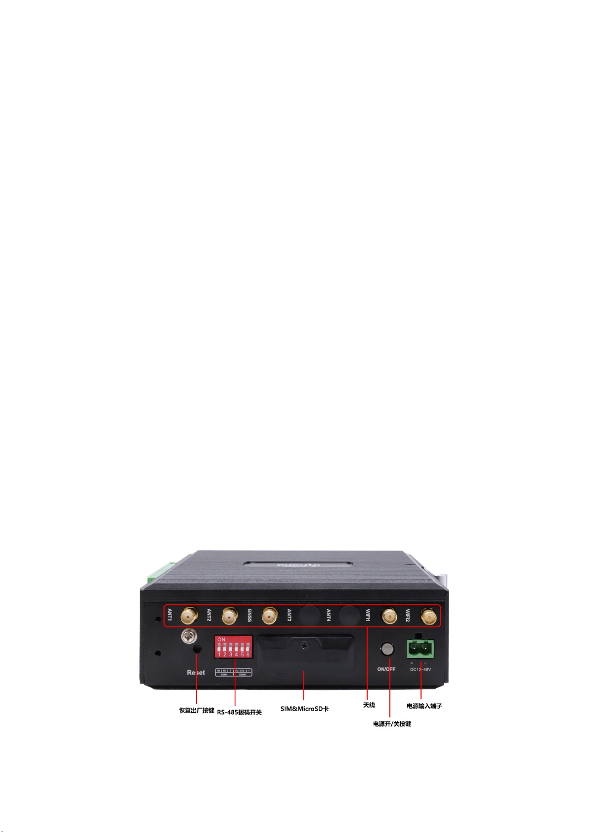
2.3.9 DC input
The EC942 supports 12 to 48V DC input
2.3.10 SIM card slot
The EC942 supports 2 SIM card slots, the SIM card needs to be installed
with power off, the SIM card is pressed into the slot.
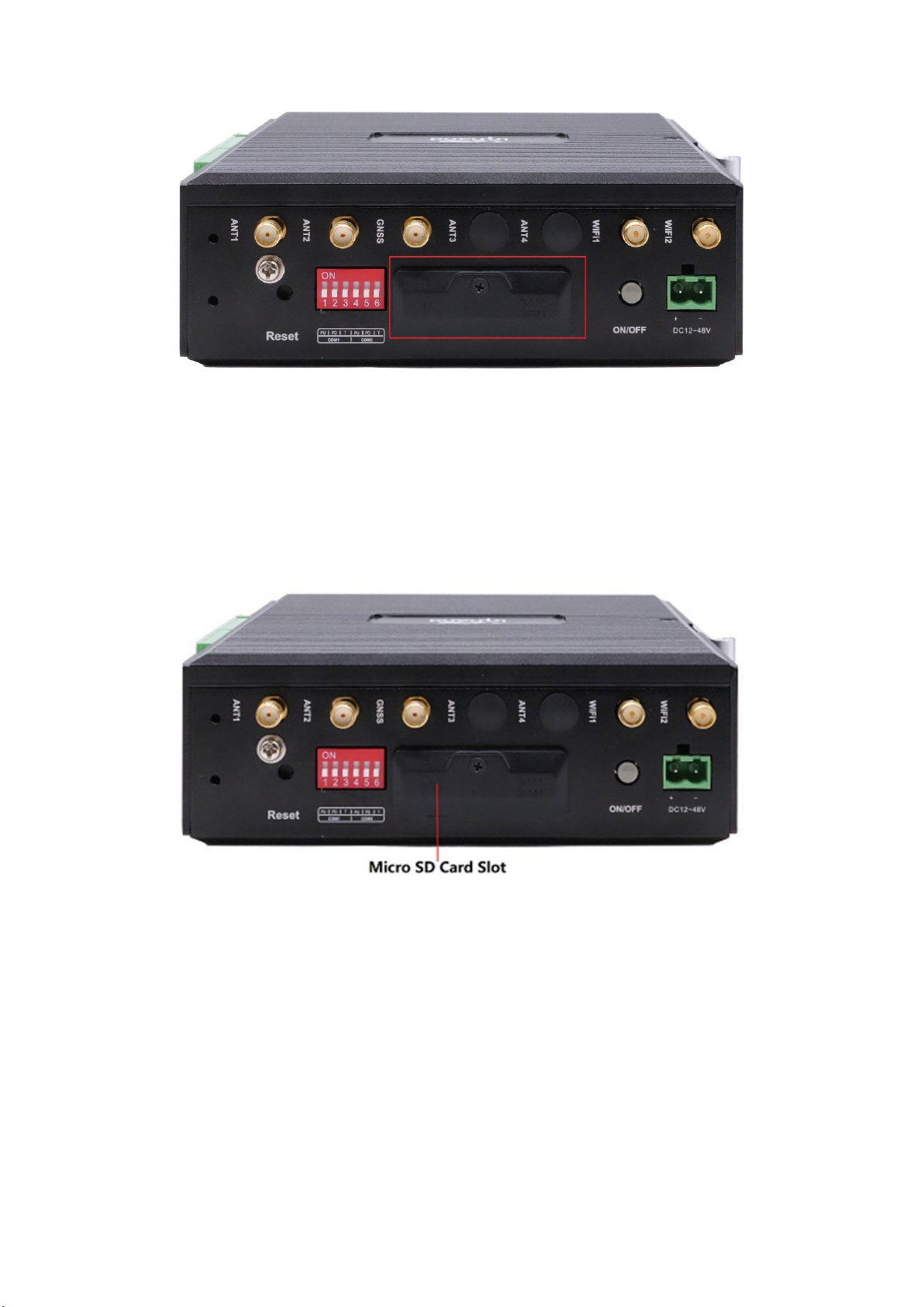
2.3.11 MicroSD card slot
The EC942 has a slot for the MircoSD card, SD does not support hotplug and needs
to be plugged in and out with power off. After inserting the SD card and powering
up the device, the system will automatically mount all partitions.
2.3.12 Restore factory keys
There is a reset button for the system to restore the factory. Refer to
Restore Factory Settings to do so.
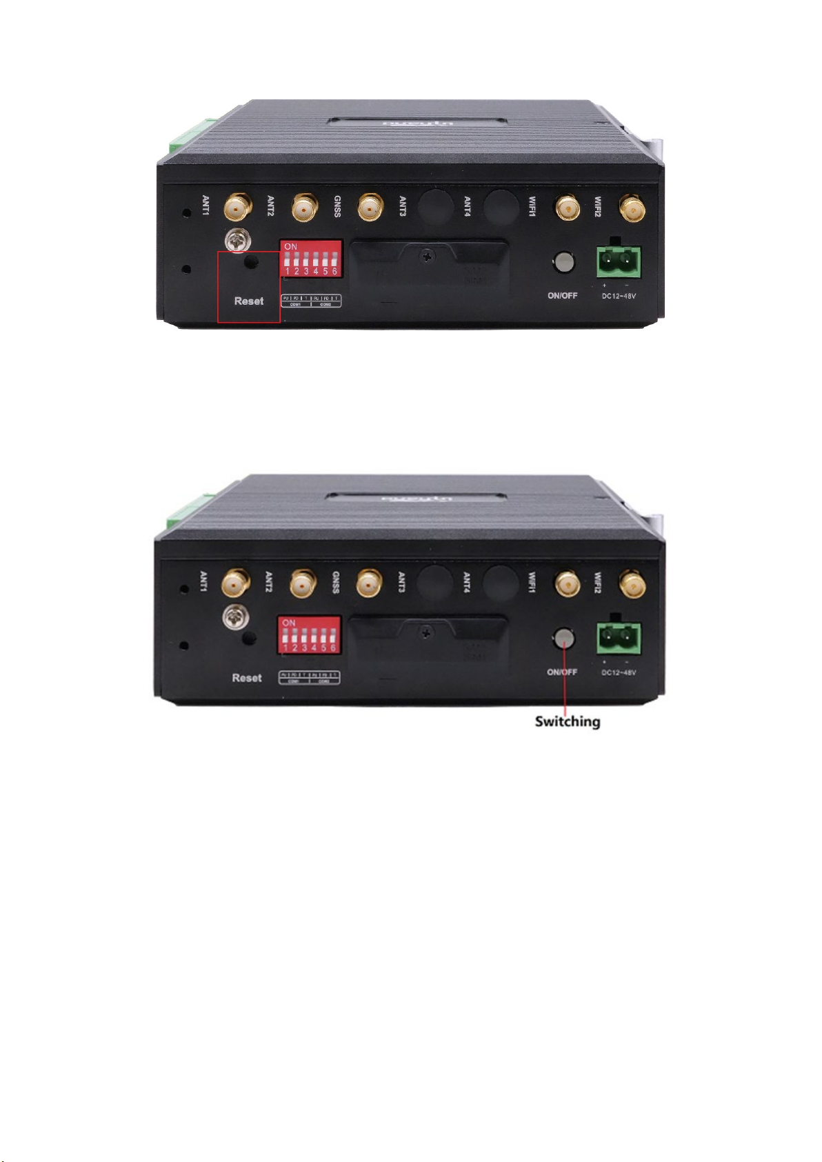
2.3.13 Switch the machine button
EC942 is equipped with an on-off button for switching the machine on and off.
2.3.14 Antenna interface
There are 5 antenna interfaces in EC942, and the number of antennas standard with
different models is different. The antenna is screwed into the corresponding
antenna interface to complete the antenna installation.
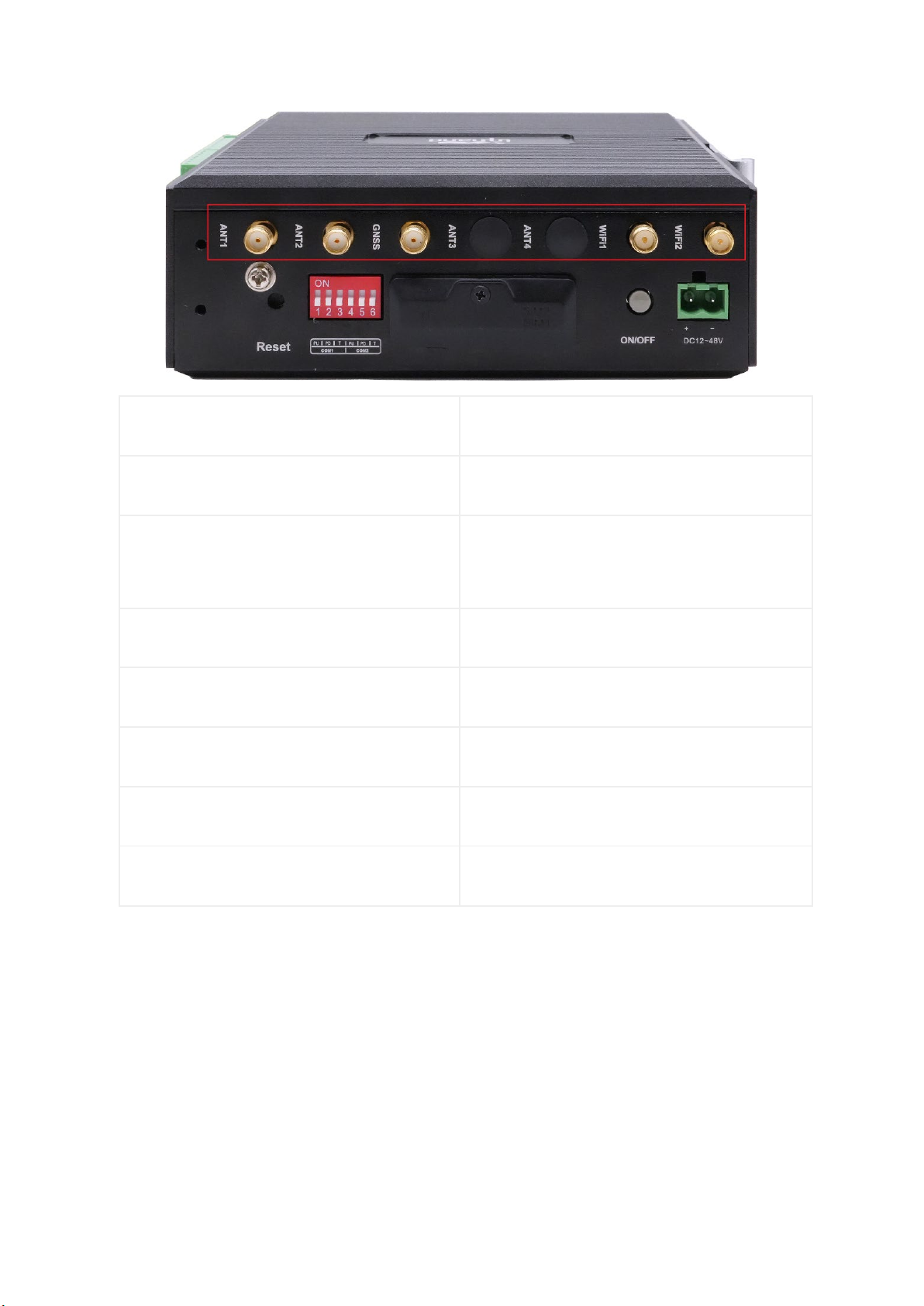
logo
Name
ANT1 4G LTE main antenna /5G antenna
ANT2
4G LTE diversity receive antenna /5G
antenna
GNSS GNSS antenna
ANT3 5G antenna
ANT4 5G antenna
WiFi1 WiFi antenna
WiFi2 WiFi antenna
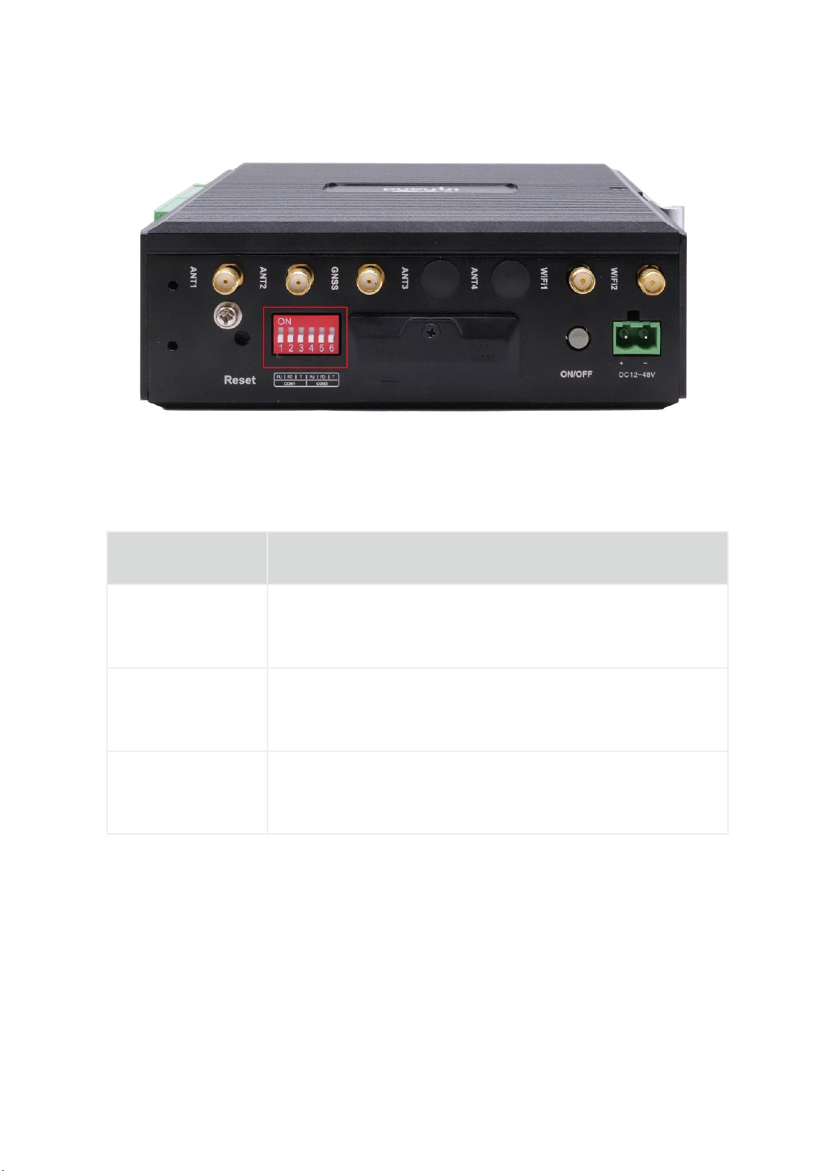
2.3.15 Dial switch
The dial switch controls the pull up and pull down resistance of the 485 bus. The
pull up and down resistance can be selected to increase the number of 485 bus
loaded devices.
Identification
Functional Notes
PU
ON - enable pull-up resistor; OFF - disables the pullup
resistor
PD
ON - enables pull-down resistor; OFF - disables the pull-
down resistor
T
ON -- Enable the terminal to match the resistor; OFF -
Disables terminal matching resistor
2.3.15 mSATA hard disk interface
EC942 supports mSata hard disk, and the factory does not come with mSata hard disk
by default. If users have large capacity storage requirements, they need to buy
mSata hard disk from themselves, or they can consult Inhantel for mSATA purchase.

3 Getting Started
In this chapter, we will cover the basic configuration of EC900, an edge
computer based on Arm architecture.
3.1 Connect to the EC900
You will need a computer that you can use to connect to the EC900 and log
in to the command-line interface. It can be connected by means of an
Ethernet cable.
Factory default username and password:
Username: edge
Password: security@edge

EC900 devices are factory created root by default, but login is disabled. If you
need to use the root user, change the system configuration manually and type sudo
-s to switch to the root user. The user edge is in the sudo group, so you can use
sudo under the edge user to execute system-level commands. See the sudo Mechanism
section in Chapter 5 for additional details.
Tips
When command not found appears, type sudo -s to switch to the root user or use
the sudo command to operate.
Note
For security reasons, we recommend that you disable the default user account and
create your own.
3.1.1 Connecting via the SSH Console
The EC900 supports SSH connections over Ethernet. Connect to the EC900 using the
following default IP address.
Port
Default IP
ETH 1
192.168.3.100
ETH 2
192.168.4.100
3.1.1.1 Linux users
Tips
These steps apply if you are connecting to EC900 on a Linux PC. Please do
not apply these steps to the EC900 device itself. Before you run the ssh
command, be sure to configure your PC's Ethernet port IP address to be
within a specific range. ETH1:192.168.3.0/24, ETH2:192.168.4.0/24.
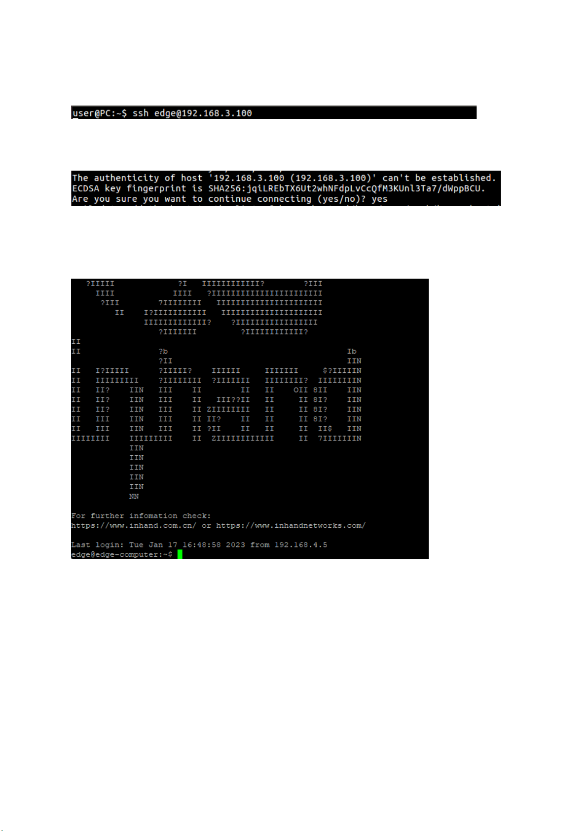
Use the ssh command to access the ETH1 port of the EC900 on a Linux PC.
Type yes to continue to complete the connection.
When the terminal prompt edge@edge-computer:~$appears and shell commands can be
entered, the connection is successful.
3.1.1.2 Windows users
Tips
These steps apply if you are connecting the EC900 on a Windows PC. Please do not
apply these steps to the EC900 device itself.
Make the following steps on your Windows PC
Other manuals for EC900 Series
1
Table of contents
Other InHand Desktop manuals


