InHand ISE Series User manual

InSwitch Industrial Ethernet Switch
ISE Series User Manual
Version 3.5
InHand Networks

User’s Manual for InSwitch ISE Series Products
Copyright Statement
copyright © 2016 InHand Networks. All right reserved and no reproduction
allowed without permission. Subjet to change without warning.
Trademark
InHand and InHand Networks are registered trademarks InHand Networks and all
other trademarks or registered trademarks in the manual belong to corresponding
manufacturers.
Disclaimer
InHand shall not be taken responsible for any modification of contents of the manual
made without permission.
This manual may contain some technical or printing errors due to human error. These
errors will be corrected periodically and will be avoided in reprint.
InHand reserves hereby the right to amend this manual without further notice to users.
Please log in our website or contact our business agent directly for revision status of
the manual.
Contact Information for Technical Support
3900 Jermantown Rd., Suite 150
Fairfax, VA 22030
USA
T: +1-703-348-2988
F:+1-703-348-2988
www.inhandnetworks.com

Safety Instructions
The product has excellent and reliable performance within its designed use, however
damage to the ISE switch should be avoided.
Please read the manual carefully and keep it for later reference.
Please pay attention to the follows when using the equipment:
Do not place the equipment close to water or wet places.
Do not place anything on power cable, which shall be kept out of reach.
Do not cover, tie or wrap-up the power cable in order to prevent fire.
Inspect the power cable and other connections regularly to ensure they are
not damaged and well connected.
Please keep the socket and plug of the optical fiber clean ,and do not looking
directly the into cross section of optical fiber during operation of the equipment.
Keep the equipment clean and wipe with soft cotton cloth when necessary.
Unless other wise instructed in the manual, please do not try to repair the
equipment by yourself.
Please disconnect power source immediately under the following circumstances and
then contact InHand Networks.
Entering of water into the equipment.
Physical damage to the equipment or cracking of the casing.
Abnormal equipment behavior or a complete change in performance.
Gas, smoke or noise generated by the equipment.

Brief Introduction to the ISE Manual
The manual is applicable for ISE2005D,ISE2008D,ISE2016D,ISE3005D,
ISE3008D,ISE3009D,ISE3010D,ISE3018D of ISE series products.
The manual contains the following chapters:
Package contents . List of goods that should be contained in packing box of
the equipment.
Product introduction. Brief introduction of the product and outstanding
features thereof.
Front panel and dimension. Front panel diagram and dimension of each and
every product of ISF series are provided.
Installation. Installation method is given in details to guide users to install the
equipment correctly.
Cable connection. Description of correct methods for connecting power
cables and communication cables.
Introduction of functions. Detailed description of features and uses.
Specifications and parameters. Description of codes and standards observed
by the product, and product specifications and parameters.
Networking models. Briefly explain the common networking models for the
ISE series switch.
Readers are instructed to read the contents carefully when the following icons are
present in the manual. Example of the icons are listed in the following table.
Note: Supplementary to main text.
Warning: Function may not be available or damage of equipment may
occur if operational instructions are not followed.
Danger: Bodily injury may occur if operation instruction is not
followed.

Contents
ISE Series User Manual..................................................................................................................1
Safety Instructions ............................................................................................................................3
Brief Introduction to the ISE Manual................................................................................................4
II. Product Introduction.....................................................................................................................8
2.1 General................................................................................................................................8
2.2 Outstanding Product Features .............................................................................................8
III. Front Panel and Dimension.........................................................................................................9
3.1 ISE2005D............................................................................................................................9
3.2 ISE2008D..........................................................................................................................12
3.3 ISE2016D..........................................................................................................................14
3.4 ISE3008D..........................................................................................................................16
3.5 ISE3009D..........................................................................................................................18
3.6 ISE3010D..........................................................................................................................20
3.7 ISE3018D..........................................................................................................................22
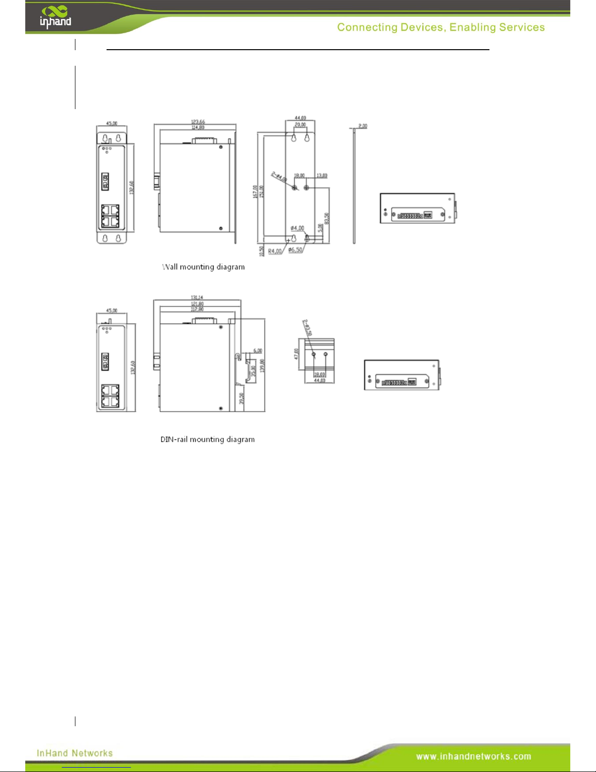
IV. Installation.................................................................................................................................25
4.1 Instruction for DIN-Rail Installation.................................................................................25
4.1.1 DIN-Rail Mounting................................................................................................25
4.1.2 DIN-Rail Removal.................................................................................................25
4.2 Instruction for Wall mounting........................................................................................26
4.2.1 Wall mount.............................................................................................................26
4.2.2 DIN-Rail Dismount................................................................................................27
V. Ethernet Cables and Wiring........................................................................................................28
5.1 10/100Base-T(X) port.......................................................................................................28
5.2 100Base-FX port.............................................................................................................30
5.3 1000Base-X, 1000Base-T(X) SFP Port...........................................................................30
5.4 Power Source ....................................................................................................................32
5.5 Grounding Protection........................................................................................................34
5.6. Alarm................................................................................................................................35
VI. Functions and Features .............................................................................................................36
6.1 LED Indicator Codes ........................................................................................................36
6.2. Dip Switches....................................................................................................................37
6.3 Introduction toAlarms ......................................................................................................38
VII. Specifications ..........................................................................................................................39
VIII. Networking Mode..................................................................................................................40
8.1 Networking of Single Set of Equipment...........................................................................40
8.2 Networking of Multiple Sets of Equipment......................................................................41
Appendix 2Glossary of Terms........................................................................................................42
Appendix 3 FCC STATEMENT ....................................................................... 错误!未定义书签。
Appendix 4 Important Safety Information......................................................................................44

I. Package Contents
Common accessories are provided for each set of ISE series products (as shown in list
of standard accessories). Please check our package carefully after taking delivery and
contact InHand sales personnel in a timely manner if any piece is missing or
damaged.
In addition, InHand can also provide users with optional accessories as per different
field conditions and customer requirements. Please refer to list of optional accessories
for details.
Standard Accessories
Accessory
Qty.
Description
Industrial Ethernet
switch
1 Device
InSwitch ISE series switch
Product documents
1 Package
Optical disk
DIN-rail
1 Piece
Fixed type switch
Product warranty
statement
1 Sheet
Warranty period is 5 years.
Optional accessories
Accessory
Qty.
Description
220VAC-24VDC
adapter
1 Set
InSwitch ISF series switch
1m optical
jumper wire
1 Piece
For user testing
Installation
accessorions
1 Set
1 piece wall-mounting accessory and 4
screws

II. Product Introduction
2.1 General
The ISE1005D series switches are designed for applications in electric power,
transportation, industrial control and other severe industrial environments. They
integrates a wide temperature range, high voltage tolerance, enterprise-class
forwarding performance, high-bandwidth, strong cabinet, protected industrial circuits
and other industrial features. They are capable of plug and play, and can satisfy
reliability requirements in the harsh industrial environment.
2.2 Outstanding Product Features
High-performance Ethernet switch technology:
IEEE802.3/802.3u/802.3x
Flow control (full duplex and half duplex flow control)
Automated speed and duplex negotiation
Broadcast storm protection
Store-and-forward switching mode
10/100M full duplex/half duplex MDI/MDI-X self adaptive
Reliable and steady operation in severe electrical environments:
Passed high-standard electromagnetic compatibility tests
Zero packet loss under intensive electromagnetic interference
Suitable for application under various severe conditions and environment:
Working temperature: -40~85 ℃
Relative humidity: 5%~95% (free of condensation)
IP40 protection class, fully enclosed and seamless type metal cabinet, and
fanless cooling
Pollution degree 2
Satisfying industrial installation requirement:
Standard industrial DIN rail or wall-mount type installation
Industrial power source terminal or I/O terminal
PCB protection coating available
Network reliability enhanced with redundancy and alarms:

Dual power-supply redundant inputs
A warning can be produced via relay after power supply failure and
interruption of port connections
III. Front Panel Layout and Dimensions
3.1 ISE2005D
Front Panel Layout
1. Power source connection and alarm
connection terminal
2. DIP switch
3. Grounding screw
4. Cover plate
5. Power source one indicator lamp
6. FX2 LINK/ACT indicator lamp
7.100Base-FX single mode/multimode
FC/SC/ST interface FX1
8. 10/100Base-T(X) RJ45 interface
9. Alarm indicator lamp
10. Power source two indicator lamp
11. InSwitch model number

12. DIN-rail bracket upper lip
13. Clamping spring
14. DIN-rail bracket attachment screw
Structural Dimensions
(Units: mm)
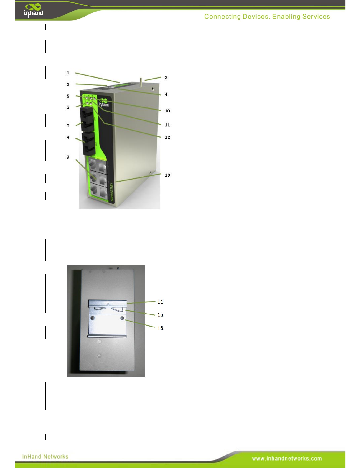
3.2 ISE2008D
Front Panel Layout
1. Power source connection and alarm
connection terminal
2. Dip switch
3. Protective grounding screw
4. Cover plate
5. Power source one indication lamp
6. Optical port FX1 LINK/ACT
indication lamp
7. 100Base-FX single mode/multimode
FC/SC/ST interface FX1
8. 100Base-FX single mode/multimode
FC/SC/ST interface FX2
9. 10/100Base-T(X) RJ45
10. Alarm indication lamp
11. Power source two indication lamp
12. Optical port FX2 LINK/ACT
indication lamp
13. InSwitch model number
14. DIN-rail bracket upper lip
15. Clamp spring
16. DIN-rail bracket attachment screw

Structural Dimensions
(Units: mm)

3.3 ISE2016D
Front Panel Layout
1. Power source connection and alarm
connection terminal
2. Dip switch
3. Grounding screw
4. Cover plate
5. Power source one indication lamp
6. Power source two indication lamp
7. Alarm indication lamp
8. Optical port FX1 LINK/ACT
indication lamp
9. Optical port FX2 LINK/ACT
indication lamp
10. 100Base-FX single mode/multimode
FC/SC/ST interface FX1
11. 100Base-FX single mode/multimode
FC/SC/ST interface FX2
12.10/100Base-T(X) RJ45 port
13. InSwitch model number
14. DIN-rail bracket upper lip
15. Clamp spring
16. DIN-rail bracket attachment screw

Structural Dimensions
(Units: mm)

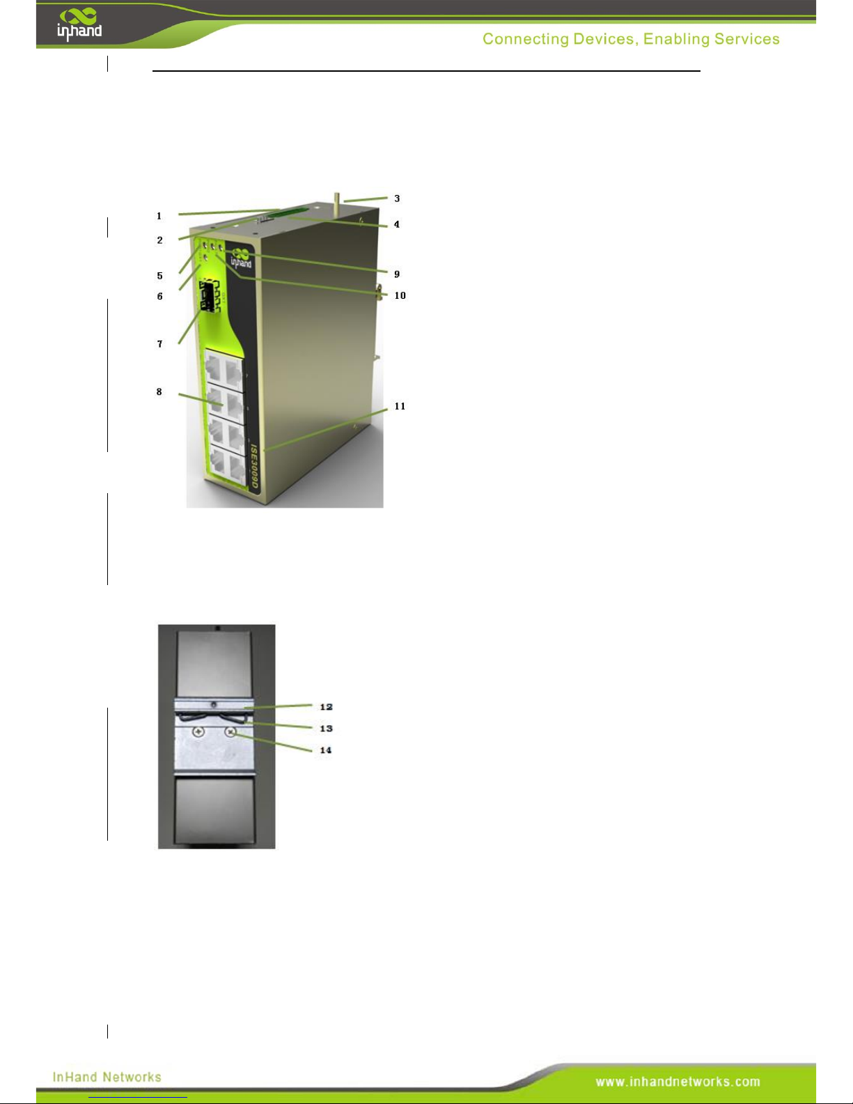
3.4 ISE3008D
Front Panel Layout
1. Power source connection and alarm
connection terminal
2. Dip switch
3. Grounding Screw
4. Cover plate
5. Power source one indication lamp
6. GX1 LINK/ACT indication lamp
7. 1000Base-X, 1000Base-T(X) SFP
port GX1
8. 1000Base-X, 1000Base-T(X) SFP
port GX2
9. 10/100Base-T(X) RJ45 port
10.Alarm indication lamp
11. Power source two indication lamp
12. GX2 LINK/ACT indication lamp
13. InSwitch model number
14. DIN-rail bracket upper lip
15. Clamp spring
16. DIN-rail bracket attachment screw

Structural Dimensions
(Units: mm)
3.5 ISE3009D
Front Panel Layout
1.Power source connection and alarm
connection terminal
2. Dip switch
3. Grounding Screw
4. Cover plate
5. Power source one indication lamp
6. GX1 LINK/ACT indication lamp
7. 1000Base-X, 1000Base-T(X) SFP
port GX1
8. 10/100Base-T(X) RJ45 port
9. Alarm indication lamp
10. Power source two indication lamp
11. InSwitch model number
14. DIN-rail bracket upper lip
15. Clamp spring
16. DIN-rail bracket attachment screw

Structural Dimensions
(Units: mm)

3.6 ISE3010D
Front Panel Layout
1. Power source connection and alarm
connection terminal
2. Dip switch
3. Grounding screw
4. Cover plate
5. Power source one indication lamp
6. GX1 LINK/ACT indication lamp
7.1000Base-X, 1000Base-T(X) SFP
interface GX1
8.1000Base-X, 1000Base-T(X) SFP
interface GX2
9. 10/100Base-T(X) RJ45 port
10.Alarm indication lamp
11. Power source two indication lamp
12. GX2 LINK/ACT indication lamp
13. InSwitch model number
14. DIN-rail bracket upper lip
15. Clamp spring
16. DIN-rail bracket attachment screw
Table of contents
Other InHand Switch manuals


Popular Switch manuals by other brands


Cisco
Cisco Nexus 7000 Series Configuration guide

ZyXEL Communications
ZyXEL Communications GS2200-24 Series Specifications

ADTRAN
ADTRAN D4 U-BR1TE V Installation and maintenance guide

H3C
H3C S12500-X Configuration guide

STEINEL
STEINEL IR 180 UNIVERSAL Information

StarTech.com
StarTech.com SV1115IPEXT instruction manual

steute
steute RF HB-4CH SW868 Mounting and wiring instructions

Rose electronics
Rose electronics UltraLink UL-V3 Installation and operation manual

NDS
NDS Priority Switch user guide

TESmart
TESmart PKS0802A10 Product description

SY Electronics
SY Electronics SMFS-81-18G user manual

IBM
IBM Flex System FC3171 Installation and user guide