Table of contents
3KC0 manual transfer switching equipment
4Manual, 09/2018, L1V30368969105-01
6.2.4 Connecting transfer switching equipment sizes 1 and 2 ....................................................... 39
6.2.4.1 Connecting a bridging bar to sizes 1 and 2 ........................................................................... 39
6.2.4.2 Connecting transfer switching equipment sizes 1 and 2 to the circuit................................... 41
6.2.5 Connecting the terminals for sizes 3, 4 and 5........................................................................ 44
6.2.6 Connecting transfer switching equipment sizes 3, 4 and 5 ................................................... 44
6.2.6.1 Connecting a bridging bar to sizes 3, 4 and 5 ....................................................................... 44
6.2.6.2 Connecting transfer switching equipment sizes 3, 4 and 5 to the circuit............................... 48
7 Operation................................................................................................................................................. 51
7.1 Operating transfer switching equipment sizes 1 and 2.......................................................... 51
7.2 Operating transfer switching equipment sizes 3, 4 and 5...................................................... 53
8 Accessories ............................................................................................................................................. 55
8.1 Component overview for sizes 1 and 2.................................................................................. 56
8.2 Component overview for sizes 3, 4 and 5.............................................................................. 57
8.3 Assembly kit for floor mounting for sizes 1 and 2 .................................................................. 58
8.4 Bridging bars.......................................................................................................................... 58
8.5 Additional poles for sizes 1 and 2 .......................................................................................... 61
8.5.1 Mounting additional poles for sizes 1 and 2........................................................................... 62
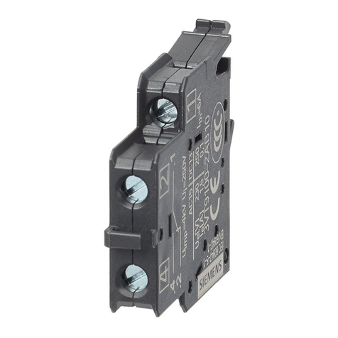
8.6 Auxiliary switches and auxiliary switch modules.................................................................... 64
8.6.1 Mounting auxiliary switches on sizes 1 and 2........................................................................ 67
8.6.2 Removing auxiliary switches from sizes 1 and 2 ................................................................... 68
8.6.3 Mounting auxiliary switches on sizes 3, 4 and 5.................................................................... 68
8.6.4 Removing auxiliary switches from sizes 3, 4 and 5 ............................................................... 71
8.7 Door-coupling rotary operating mechanism of the 8UD1 series............................................ 72
8.7.1 Component overview ............................................................................................................. 73
8.7.2 Types of delivery and versions .............................................................................................. 74
8.7.3 Mounting the door-coupling rotary operating mechanism ..................................................... 74
8.7.3.1 Use the hole drilling template for the cabinet door ................................................................ 74
8.7.3.2 Mounting the handle on the cabinet door .............................................................................. 76
8.7.3.3 Calculating shaft length and cutting shaft to size................................................................... 77
8.7.3.4 Attaching the door-coupling driver to the shaft ...................................................................... 79
8.7.4 Function and operation .......................................................................................................... 83
8.7.4.1 Door padlocking ..................................................................................................................... 83
8.7.4.2 Tolerance compensation........................................................................................................ 87
8.7.4.3 Padlocking.............................................................................................................................. 88
8.7.4.4 Assigning the switch position between the 8UD1 handle and 3KC0..................................... 90
8.7.5 Accessories for the 8UD1 series............................................................................................ 92
8.7.5.1 Handles .................................................................................................................................. 92
8.7.5.2 Coupling drivers ..................................................................................................................... 93
8.7.5.3 Extension shafts..................................................................................................................... 94
8.7.5.4 Shaft coupling ........................................................................................................................ 95
8.7.5.5 Shaft jack for 3KC0 sizes 1 and 2.......................................................................................... 96
8.7.5.6 Inscription label ...................................................................................................................... 97
8.8 Direct operating mechanism .................................................................................................. 98
8.8.1 Direct operating mechanism for sizes 1 and 2....................................................................... 98
8.8.1.1 Mounting the direct operating mechanism on sizes 1 and 2 ................................................. 99
8.8.1.2 Removing the direct operating mechanism from sizes 1 and 2........................................... 100
